I/O Setup
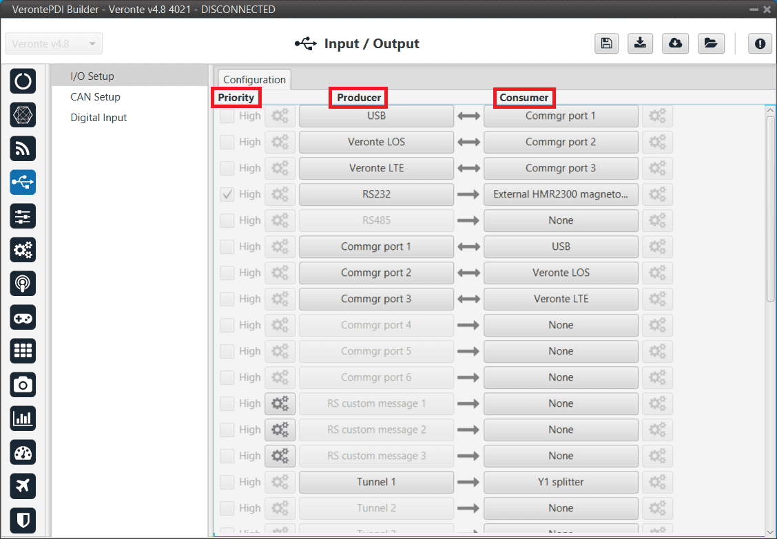
In this panel the user can stablish the relationship between a determined signal with a I/O port. This allows users to configure external sensors, messages between 1x units (Tunnel) and custom messages.
I/O Setup menu
Priority: Connections between I/O ports can be marked with high priority with this checkbox. If enabled, they will run at high frequency: 1000 Hz.
Producer: Functions for creating and sending messages.
Consumer: Functions for receiving and parsing messages
I/O Setup consumer options
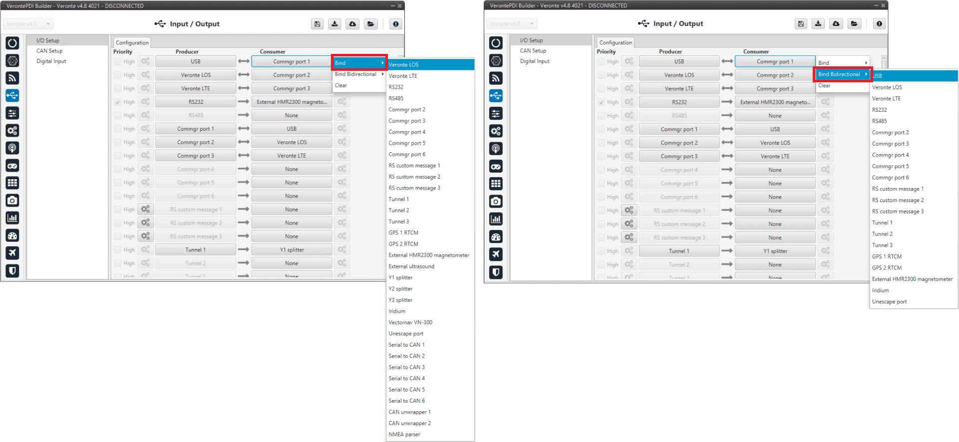
Firstly, users have to configure the Producer selecting the I/O port or information to use. Later, users have to configure the Consumer by clicking on an element, a new window will be displayed to select an item. The relationship between them can be unidirectional (Bind) or bidirectional (Bind Bidirectional), the last enables a port to receive or send information.
The following I/O ports are available:
Field |
Description |
|---|---|
USB |
USB Port |
Veronte LOS |
Radio |
Veronte LTE |
4G Connection |
RS232 |
Serial Port 232 |
RS485 |
Serial Port 485 |
Commgr port |
COM Manager ports send and receive VCP messages. This is the protocol used by Veronte products to communicate. For more information on VCP, read the VCP user manual |
Tunnel |
Creates a bidirectional brigde between two devices, see Tunnel |
RS Custom Message |
This allows user to send/receive a serial custom message, see Serial Custom Messages |
GPS RTCM |
This allows the user to send/receive RTK information from GND unit to AIR unit |
External HMR2300 magnetometer |
External magnetometer sensor, see External HMR2300 magnetometer |
Iridium |
Iridium communication, see Iridium section |
Splitter |
Used to split a signal into 2 |
NMEA Parser |
NMEA 0183 messages parser, see NMEA Parser |
Unescape port |
This allows user to reconstruct a byte stream with an escape logic, see Unescape port |
CAN to serial / Serial to CAN |
Serial to CAN sends serial streams over a CAN Bus / CAN to serial undoes the transformation ‘Serial to CAN’ |
CAN wrapper / CAN unwrapper |
CAN wrapper sends CAN streams over a serial Bus / CAN unwrapper undoes this transformation |
External ultrasound |
External ultrasound sensor, see Internest section |
Vectornav VN-300 |
Vectornav VN-300 is an external IMU. For more information, see the Vectornav VN-300 -> Integration examples section of this manual |
More information about some elements can be found in the following sections.
Tunnel
It is possible to configure a Tunnel which is a bidirectional bridge between 1x units that communicate to each other sharing information about an external device connected to the Serial or Digital port.
Imagine that it is desired to have a button connected to the air 1x autopilot to launch a parachute. It is not possible to physically connect the button because the air autopilot is in the flying platform, so a different option is needed. Here is where the tunnel becomes useful. The button could be connected through the Serial or Digital port to the Ground 1x autopilot, and then with the tunnel send the signal to the air one. With this configuration it would be like if the button were physically connected to the aircraft.
Let’s consider the following image:
Tunnel configuration
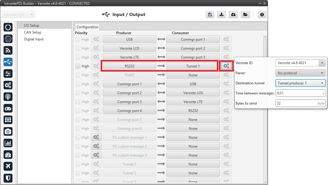
In the image above there is a device connected to the RS232 (Producer) and there is a Tunnel (Consumer) which sends that information to other 1x autopilot with a determined ID. On the other hand, 1x air unit has to be configured to receive the signal sent by other device. In that case the Producer will be Tunnel and Consumer will be the port or destination tunnel where the device is connected.
The options available when configuring Tunnel as Consumer are:
Veronte ID: Select the address that will receive the information.
App 2: Veronte Ops address.
Broadcast: All units on the network. Select this option for a generic configuration.
Veronte v4.X XXXX: Address of a specific Veronte unit, it can be a 1x, a 4x, a CEX, etc.
Parser: The user can choose protocol to parse message data. The options available are:
No protocol
RTCM3
CANserial
Destination tunnel: Number of port is used to avoid mistakes and identify a Tunnel when using more than one, Tunnel 1, 2 and 3 are available.
Time between messages.
Bytes to send: Sets the message size to send.
When configuring Tunnel as Producer (i.e. on the unit that receives the information), no configuration is required. It is only necessary to connect it to a Consumer, usually to a serial port.
Serial Custom Messages
Warning
1x autopilot has a serial limitation of 64 vectors (fieldset) per Custom.
In addition, there is a limit shared with all Customs, including CAN Custom Messages:
Maximum number of vectors (fieldset): 104
Maximum number of fields: 2000
It is possible to configure the messages sent/received through the serial port and its conversion to system variables by selecting the option RS Custom message and configuring the I/O port.
Serial Custom Messages
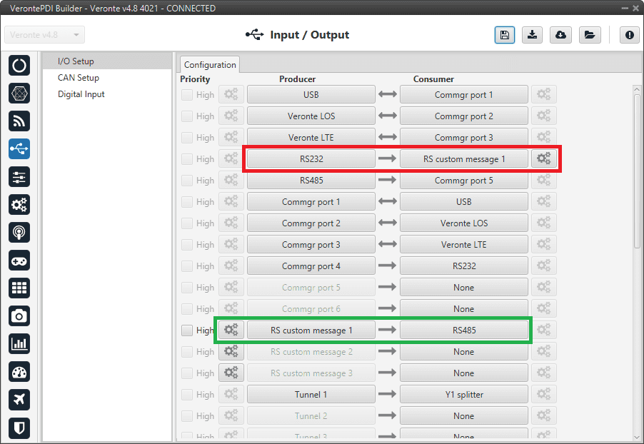
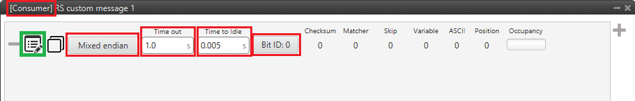
In the image above can be seen two possible configurations using a RS Custom Message. The ‘red’ one is configured to receive a determined message from a RS-232 serial port and the ‘green’ is used to send a RS Custom Message through a RS-485 serial port. It is also possible to use the same RS Custom Message for both tasks if Bind Bidirectional is used (the arrow indicates this).
To configure a RS Custom message, the user must follow the next steps:
Press the configuration button (
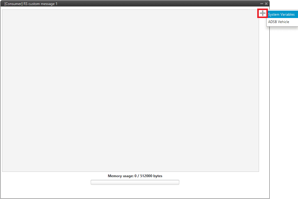
 icon) and another window will be displayed. In this window press the
  icon to add a custom message, the user can choose between System variables or ADSB Vehicle.
Serial Custom Message configuration
Note
The difference between System variables and ADSB Vehicle is that when the user has selected the second option, only the ADSB variables will appear and not all the ones available in 1x PDI Builder.
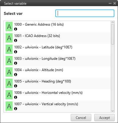
ADSB Vehicle Variable custom message
When it is already added, the following options are available to configure a custom message:
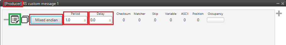
Producer RS Custom Message configuration
Consumer RS Custom Message configuration
Endianness: Depending on the order in which the device issue the message, it is possible to select:
Big endian: Set the value from left to right.
Little endian: Set the value from right to left.
Mixed endian: Some devices use this format. If users need to configure it, please contact the support team (create a ticket in the customer’s Joint Collaboration Framework; for more information, see Tickets section of the JCF manual).
Period/Time out: This option has a dual role depending on if it is used to transmit or receive data.
Period - Producer: It is the inverse of the send frequency.
Time out - Consumer: This is the threshold time between receptions to consider that the message is not being received correctly.
Delay/Time to Idle: This option has a dual role depending on if it is used to transmit or receive data.
Delay - Producer: It is a delay applied before sending the message. This serves to send messages with the same period without overloading the Serial bus.
Time to Idle - Consumer: This is the time 1x autopilot waits before discarding partially parsed bytes.
Bit ID: This option is only available when a message is configured as Consumer. The user bit selected in Bit ID box will be true if the message is being received correctly.
Warning
Pay attention that the user bit selected in Bit ID is not in use for another task.
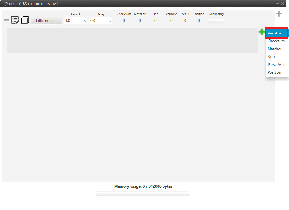
To create the structure of the message, click on the edit message button (
 icon) and then press the icon to add fields to it.
The following type of messages are available to configure a structure: Variable, Checksum, Matcher, Skip, Parse ASCII and Position.
The configuration of each structure is covered in Custom Messages types section.
Warning
Before configuring any message, user has to know the structure it has to have according to the device that is connected to the port. Each device may have a different message structure when it sends or receives information.
To check serial messages transmission, see the Debug serial messages transmission -> Troubleshooting section of this manual.
NMEA Parser
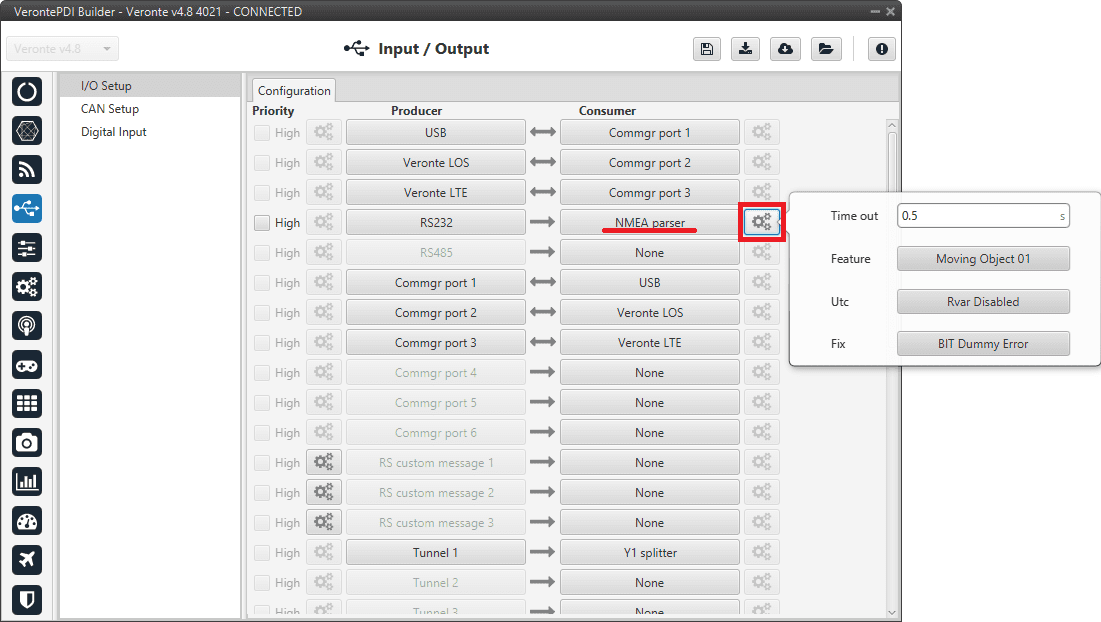
NMEA Parser is another way to add an axternal GNSS device. This consumer allows to receive NMEA 0183 messages and parses them directly. The NMEA Parser configuration menu includes the following parameters:
NMEA Parser configuration
Time out: Defines the period of incoming information from the external system.
Feature: Variable extracted from the message defining the GNSS position. Usually Moving Object variables are used in 1x PDI Builder.
Utc: Variable extracted from the message defining the UTC.
Fix: Data provided by the external device which is important to know the status of the positioning.
Once the NMEA message has been parsed, the variables used for Fix and Feature can be selected in the GPS External configuration of the GNSS block as Fix Bit and GPS Position. For more information about this configuration, see Sensors blocks section.
Unescape port
To understand what unescape is, the user must first understand what an escape byte is.
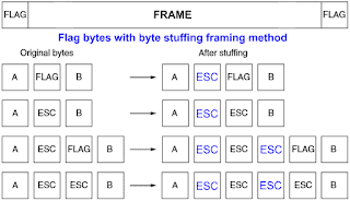
Let’s consider that there is a protocol that defines a ‘Flag’ as the start and end byte of the frame. In case the flag or an escape value appears in the frame data, and in order not to misinterpreted the message, an escape byte or the same value repeated will be added before them so that, at the time of parsing, it will be reconstructed with the original byte.
Escape byte
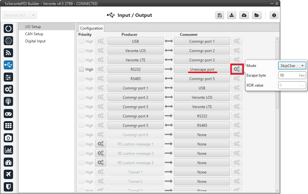
In 1x PDI Builder, an Unescape port has been implemented to allows to reconstruct a byte stream with an escape logic.
Unescape port configuration
Two modes of escapes are supported:
SkipChar: The unfolding of the value to be escaped, the byte to escape has been repeated in the message.
SkipAndXOR: In this case, the escape byte is entered first and then the value to escape (i.e. the value to escape XOR escape byte).
In addition to this, two more options are available in this pop-up window:
Escape byte: Escape byte added.
XOR value: Only available when ‘SkipAndXOR’option is selected.