 Devices
This menu displays the possible payloads/devices that can be configured with Veronte Autopilot 1x. Each section will allow the user to configure different parameters from the available variety of payloads.
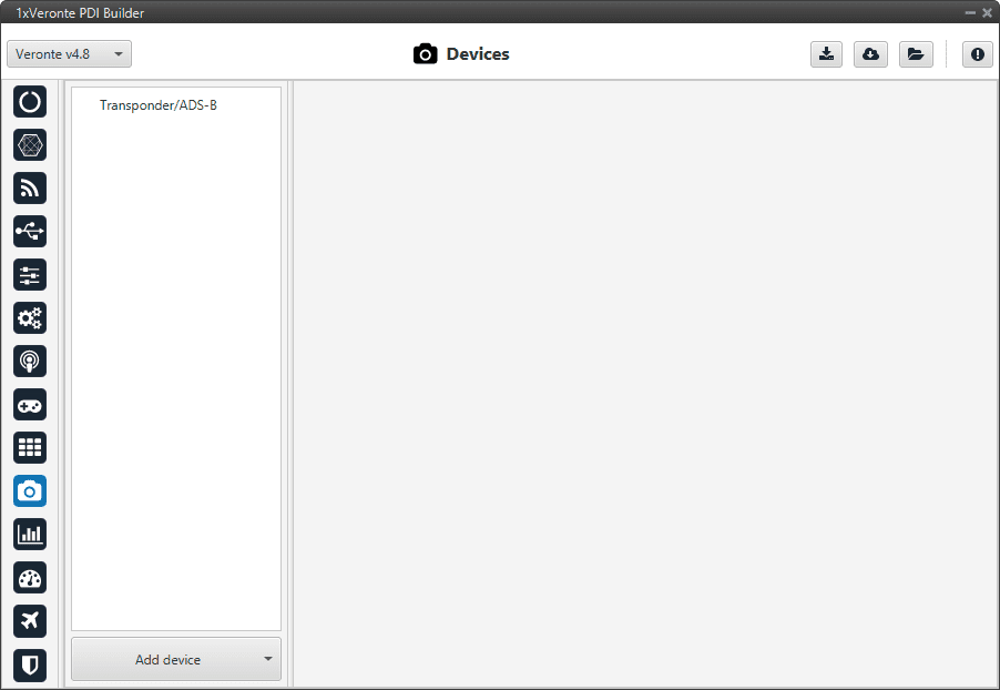
Devices menu
By default, only the Transponder/ADS-B device is added to this menu (as shown in the figure above). However, users can added other devices supported by Veronte Autopilot 1x simply by clicking Add device:
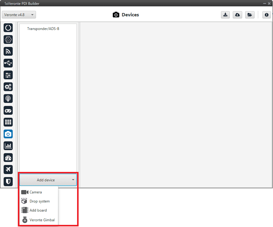
Add devices
Transponder/ADS-B
A transponder is a device that generates or parses ADS-B messages. This menu allows the user to use/configure a transponder through Custom Messages.
There are 2 different types of ADS-B:
ADS-B In: When the transponder sends the detected UAVs.
ADS-B Out: When the transponder wants to send the position of the UAV.
The interface includes both types and, depending on the model (type) selected, the configurable parameters for ADS-B In or ADS-B Out are enabled.
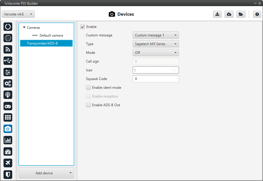
Transponder/ADS-B section
The parameters that appear in this menu and that must be configured by the user are explained below:
Enable: Check it to activate a transponder device.
Custom message: Select the Custom message 1-3 to be used for the information exchange, as it will be automatically filled with the information required by the transponder/ADS-B.
Type: Veronte Autopilot 1x is compatible with:
Sagetech MX Series
uAvionix ping 20s
uAvionix ping 1090i
Daedalean
Sagetech XPS-TR
Sagetech XPG-TR
Sagetech XPS-TRB
Mode: The available modes are:
Off: Transponder switched off.
Standby: Transponder will not respond to interrogation.
ON: Replies to interrogations with 4-digit squawk code.
ALT: Replies to interrogation with altitude information.
Important
The parameters detailed above are common for ADS-B In and Out, the following depends on the selected Type.
Call sign: Communication call sign assigned as unique identifier to the aircraft.
Icao: Unique ICAO 24-bit address permanent for the aircraft, which becomes a part of the aircraft’s Certificate of Registration.
It is represented by six hexadecimal characters.
Note
Only available for ALT mode.
Squawk Code: Users must introduce the Squawk Code provided. This is the transponder code to in order to identify the flight. For certain type of flights and/or situations, specific transponder codes are used.
These codes are four/digital octal numbers.
Enable Ident Mode: This is an identification of the UAV at the request of ATC, in order to help them to locate the aircraft.
Note
Only available for ON and ALT modes.
Enable reception: Enables reception (ADS-B IN).
Enable ADS-B Out: Enables transmission (ADS-B OUT).
Cameras
Adding a camera will create a default Camera configuration menu.
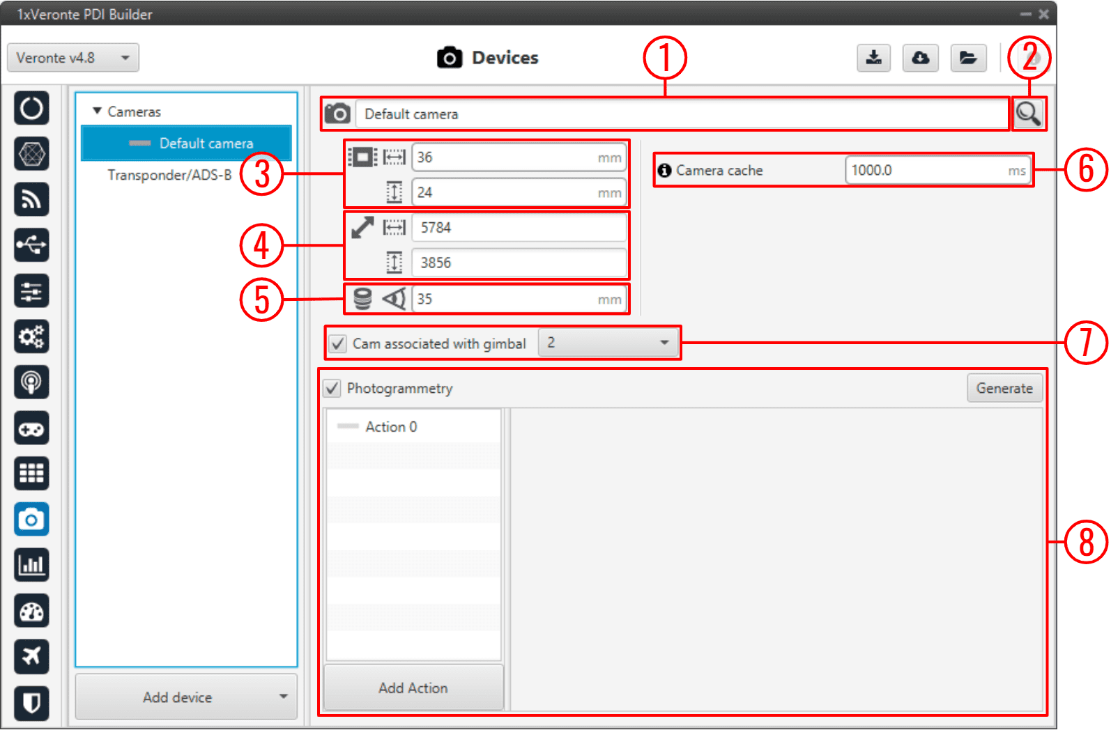
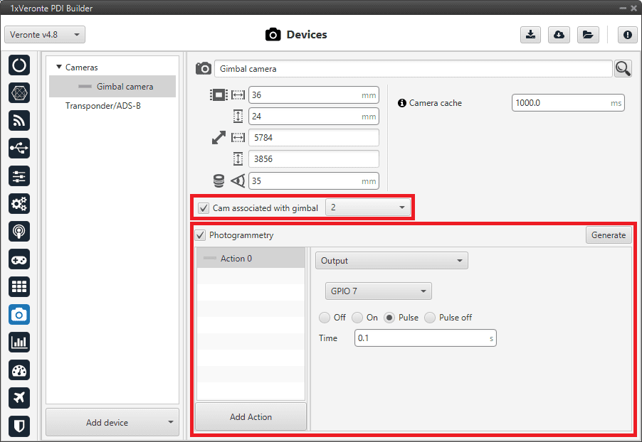
Cameras section
Name: Give a name to the customized camera.
Search: Users can also choose a camera from the predefined list of cameras, which will automatically establish the values of the Sensor, Resolution and Lens parameters.
Sensor: Defines the camera sensor width and height in mm.
Resolution: Defines the camera resolution width and height.
Lens: Defines the focal length from the camera in mm.
Camera cache: Defines the cache time used to play the selected camera on the gimbal widget.
A higher cache might increase the video delay.
A lower cache might cause video artifacts or disconnections.
Tip
333 miliseconds should be enough for a 1080p video.
Cam associated with gimbal: If the camera is from a Gimbal device, it is important to configure this field and select the the Gimbal block number that is related to this camera.
Photogrammetry: This allows the creation of Photogrammetry actions.
The actions performed in a Photogrammetry mission can be defined here, following the same possibilities as in Actions - Automations.
Add Action: Will add a new action.
Warning
A maximum of 4 Actions can be defined (Actions 0-3).
Generate: Clicking on ‘Generate’ will create the automation ‘Photogrammetry’ with a Button as event and with the actions defined here.
An example is given below:
Cameras - Example
The automation created for Photogrammetry is shown below:
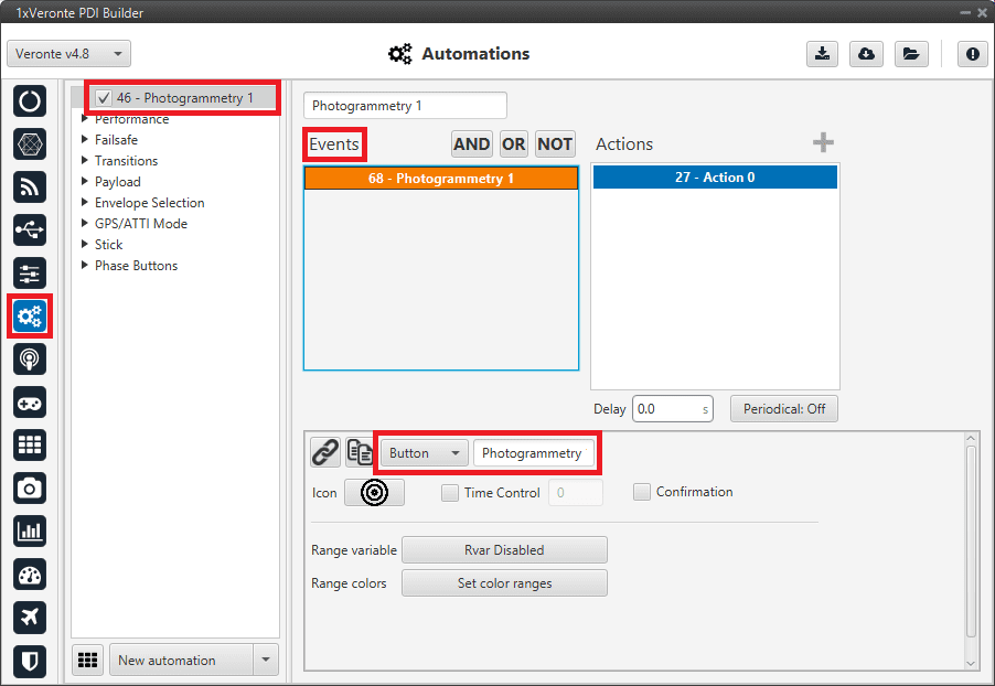
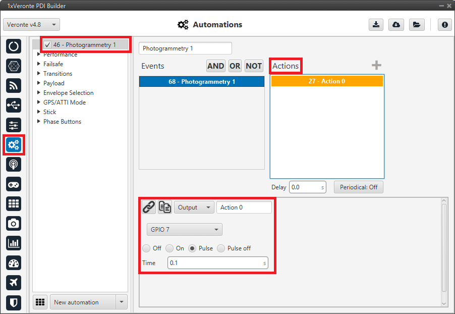
Cameras - Automation example
Board
This board menu allows the user to configure communicate via CAN, in 1x PDI Builder, with another device such as CEX, MEX, MC01, etc., in only 1 step, so in only 1 interface window. Instead of doing it in several steps, as is explained in CEX - Integration examples or MC01 - Integration examples.
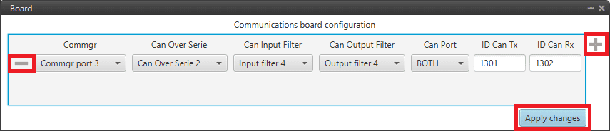
Board section
Click on the
 icon to add a new field. The following parameters must be defined:
Commgr port: Select the desired COM Manager port: Commgr port 1-6.
Can Over Serie: Select the desired Serial to CAN / CAN to serial: Serial to CAN 1-2/CAN to Serial 1-2.
Can Input Filter: Select the desired input filter to use: Input Filter 1-2.
Can Output Filter: Select the output filter the user wishes to use: Output Filter 1-2.
Can Port: CAN A, CAN B or BOTH can be selected.
ID Can Tx: Enter the ID of the CAN message to be sent.
ID Can Rx: Enter the ID of the CAN message to be received.
Warning
Be careful not to select a producer/consumer that is being used for another purpose, as the configuration defined here has “priority” and will be changed to this.
For more information on these parameters, see Input/Output section of this manual.
Clicking the
 icon will remove the field and display a confirmation warning message.
By clicking on ‘Apply changes’, all these CAN communication settings are applied to the Autopilot 1x configuration.
Below is an example of before/after when changes are applied:
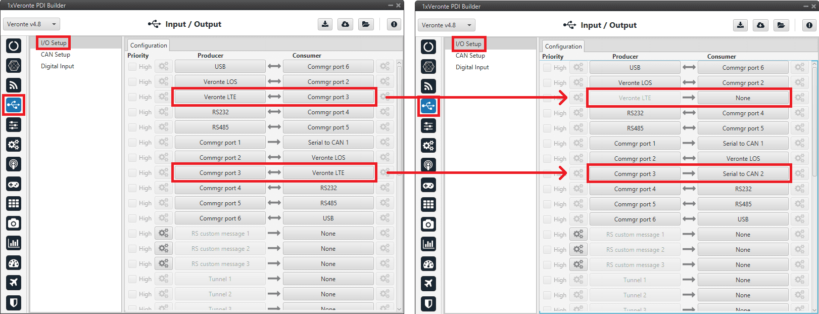
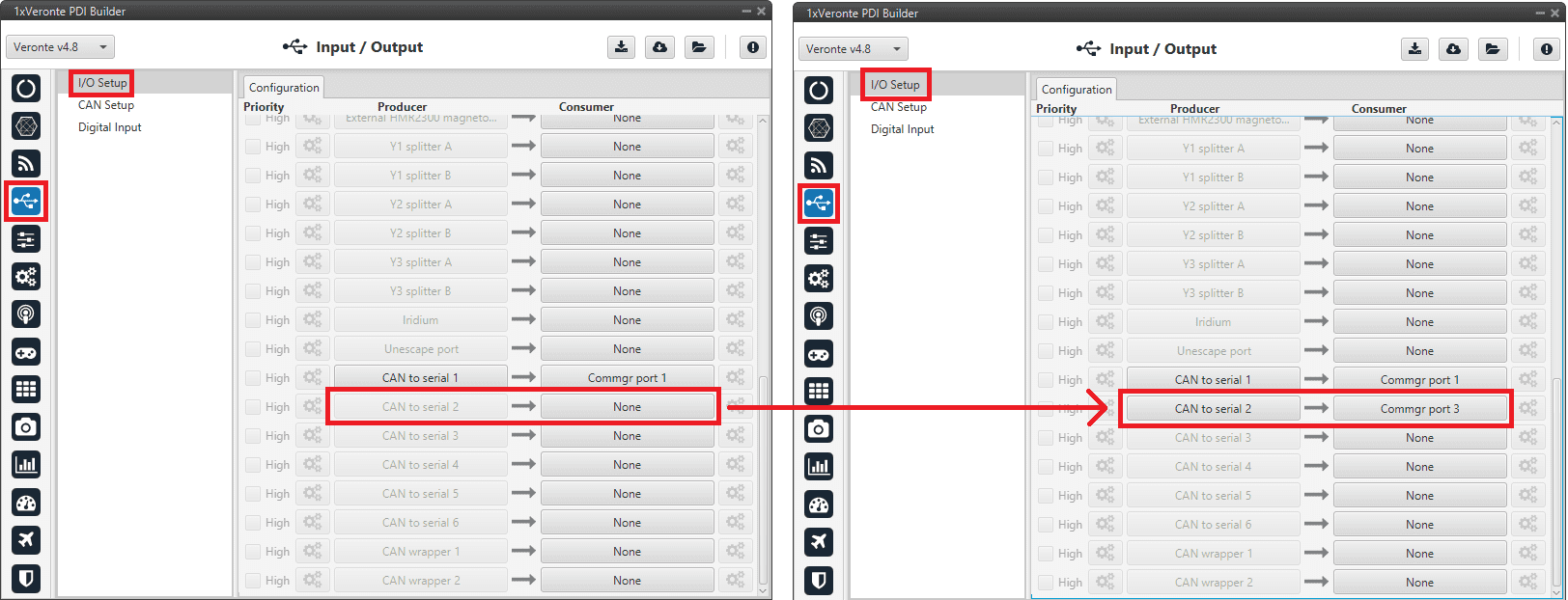
Board - I/O Setup configuration
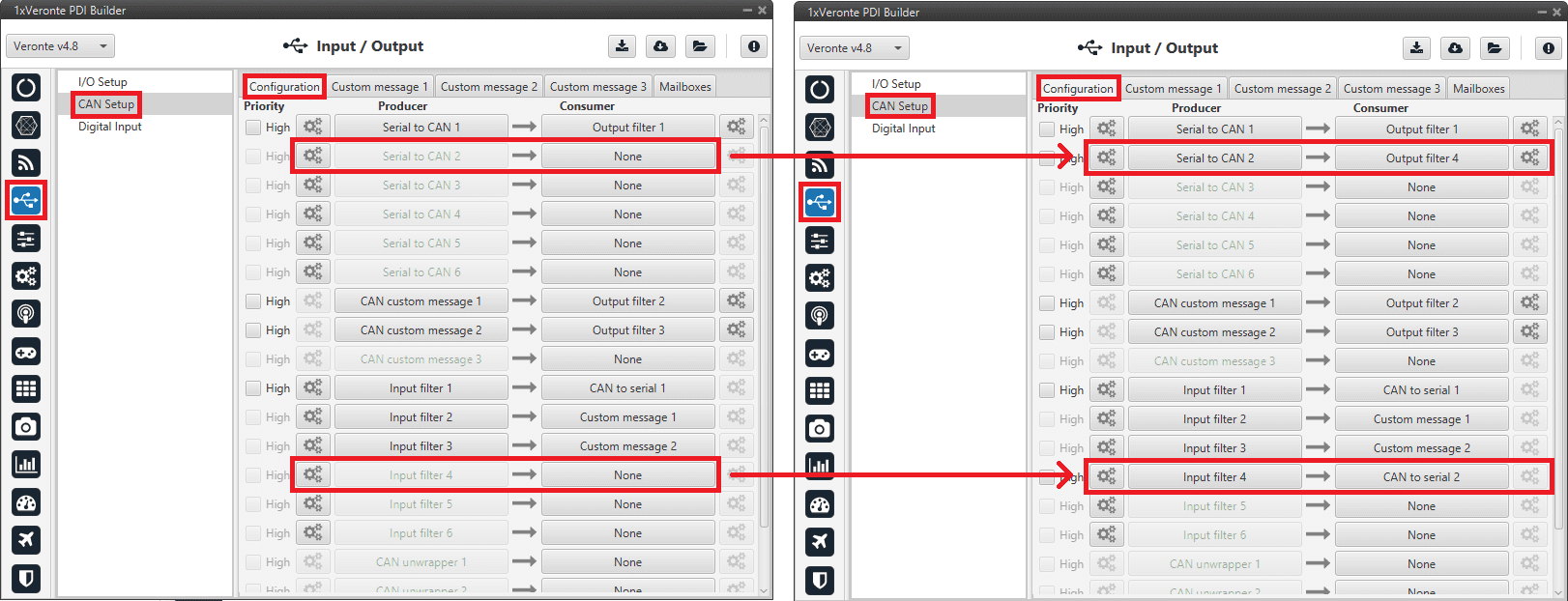
Board - CAN Setup configuration
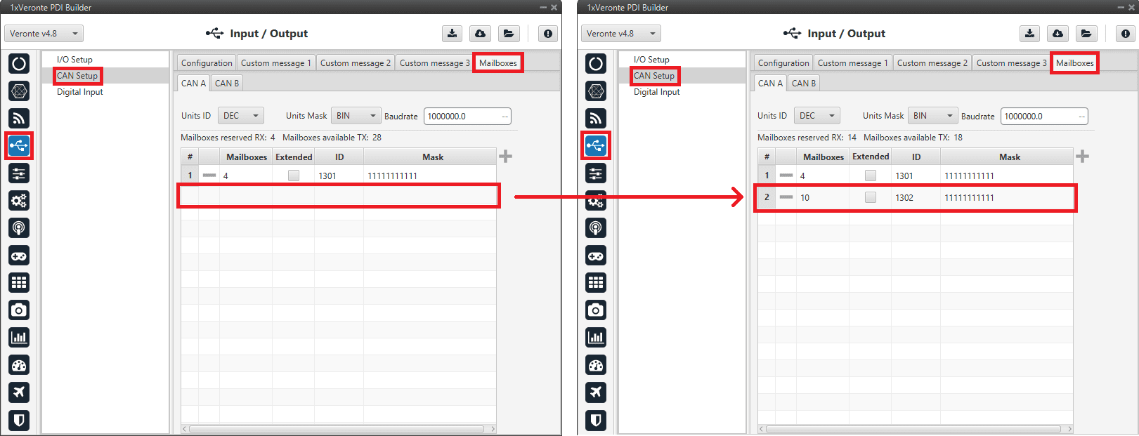
Board - Mailboxes configuration