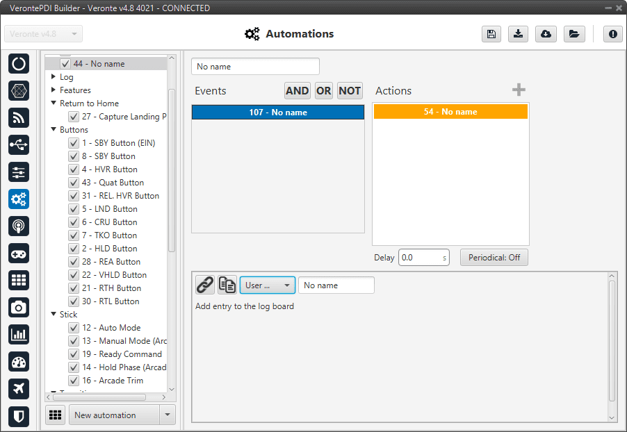
Actions
An action is something that will be performed when the event (or group of events) has been accomplished. The actions box contains all the actions created.
The user can also rename the event with the name of his choice.
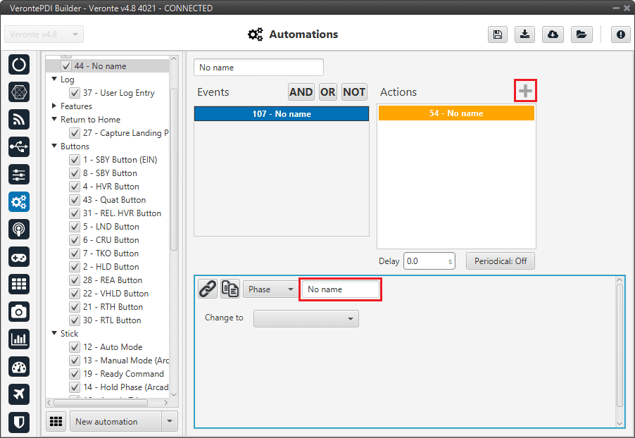
Actions menu
When creating a new event it is possible to choose from one of the previously created on the system or to create a new one.
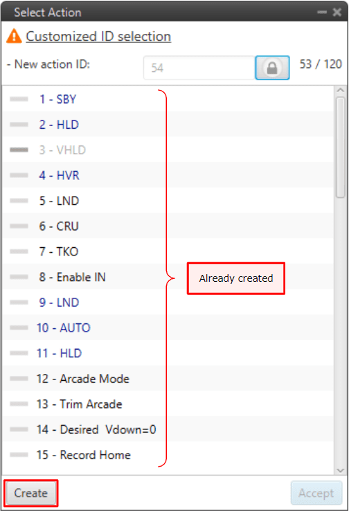
New action
Below are present the different types of actions that can be created.
Atmosphere Calibration
This action allows the atmosphere calibration in the same way as shown in the Operational panel of Veronte Ops (for more information about atmosphere calibration click Veronte Ops manual).
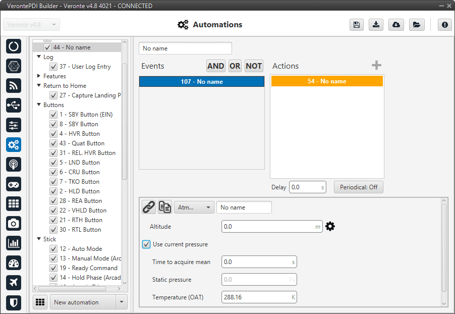
Atmosphere Calibration action
The following options can be configured:
Altitude: Actual MSL altitude. The user must choose between entering this value manually or selecting a system variable.
User current pressure: By enabling it, the static pressure will be read from the static pressure sensor during the specified time (Time to acquire mean).
Static pressure: If the above option is not enabled, the actual static pressure should be specified manually.
Temperature (OAT): Outside air temperature.
Change active sensor
This option allows the change of the actual sensor used as accelerometer, gyroscope and dynamic pressure.
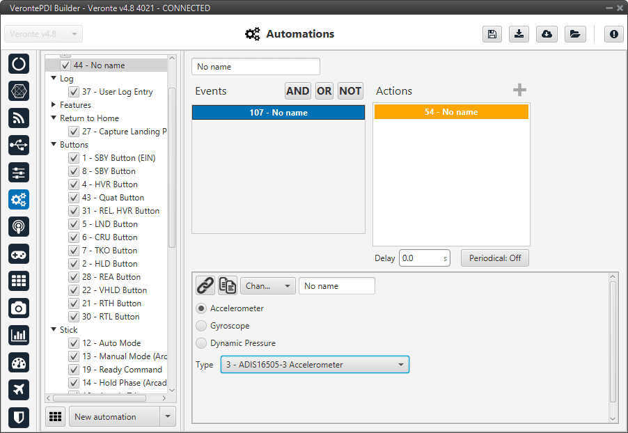
Change active sensor action
Command block
This action allows the user to configure gimbal or trim the radio controller.
Note
This action is disabled by default when 1x autopilot is started. To activate it, the user have to create a gimbal block or an arctrim block (see more information about it in Block Programs).
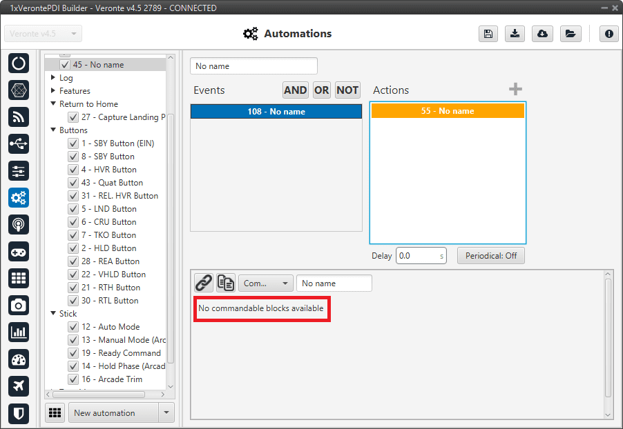
Command block action
Gimbal
When this action is triggered, the gimbal control is enabled. There are several control modes that are explained below.
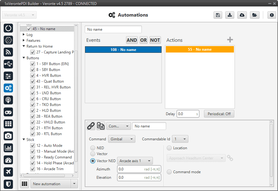
Command block action - Gimbal
Commandable Id: Id of the commandable Gimbal block (users can look up this Id in the block to be commanded, in Block Programs section).
NED: Control using NED axis, defining the initial position through azimuth and elevation.
Vector: This control uses aircraft body axis. The initial position is defined through roll and tilt.
Vector NED: In this case the axis should have been defined in Arcade Axis.
Location: The gimbal will point towards the projection on the ground at the specified point.
Command mode: Gimbal control is done externally, e.g. via VCP commands.
ArcTrim
This action trims the radio controller, i.e sets as zero the current sticks positions.
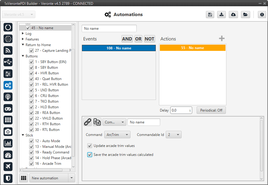
Command block action - ArcTrim
Commandable Id: Id of the commandable ArcTrim block (users can look up this Id in the block to be commanded, in Block Programs section).
Update the arcade trim values: If this option si enabled, the stick is trimmed but not saved in the configuration. This means that if 1x autopilot is restarted the trimming is lost.
Save the arcade trim values calculated: Trim values are stored for future flights.
Custom CAN TX
When this action is triggered, a previously configured CAN message is sent through the CAN bus. The message has to be configured in CAN Custom messages section of the Input/Output menu.
Warning
As this automation is used to send a single message on demand, in its configuration in Custom Messages, the user has to set its period to -1. This way, this message will only be sent when this action is triggered.
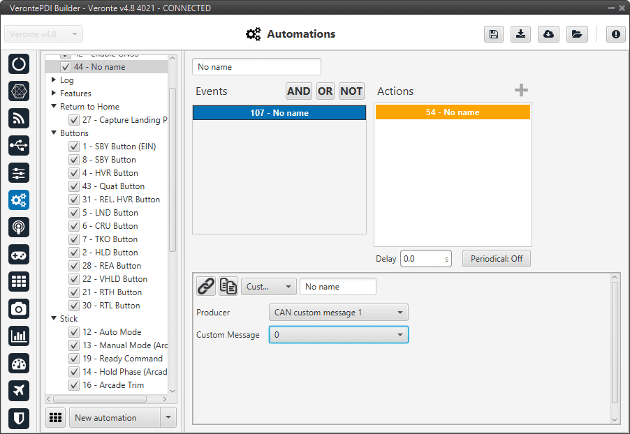
Custom CAN TX action
The two parameters to configure in this action are:
Producer: The user has to specify where the custom message is located: CAN custom message 1, 2 or 3.
Custom message: The number of the custom messages that will be sent.
Custom Serial TX
When this action is triggered, a previously configured serial message is sent through the serial port (RS232 or RS485). The message has to be configured in Serial custom messages section of the Input/Output menu.
Warning
As this automation is used to send a single message on demand, in its configuration in Custom Messages, the user has to set its period to -1. This way, this message will only be sent when this action is triggered.
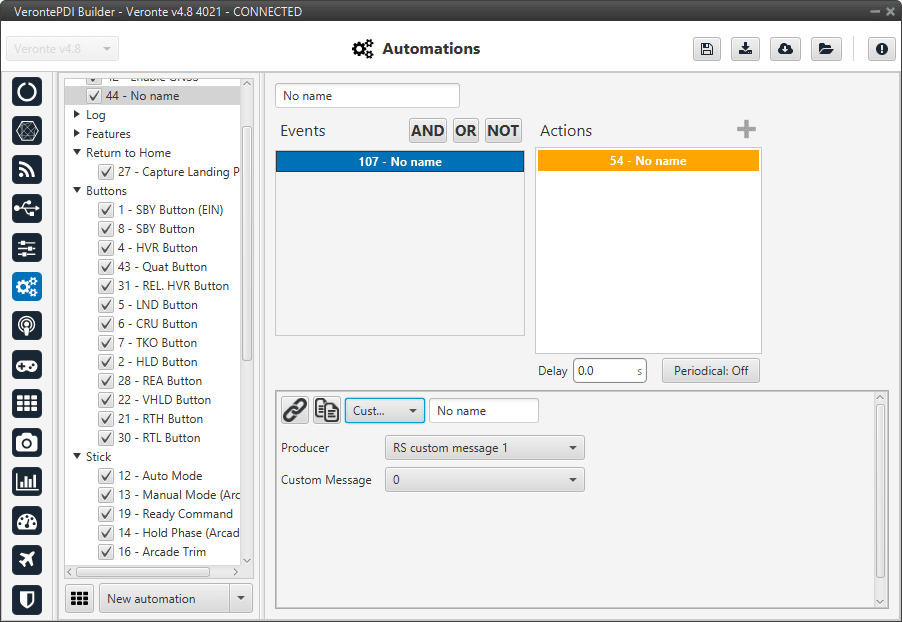
Custom Serial TX action
The two parameters to configure in this action are
Producer: The user has to specify where the custom message is located: RS custom message 1, 2 or 3.
Custom message: The number of the custom messages that will be sent.
DEM calibration
This option allows the calibration of the digital elevation model by setting the actual AGL value in the same way as shown in the Operational panel of Veronte Ops (for more information about DEM calibration click Veronte Ops manual).
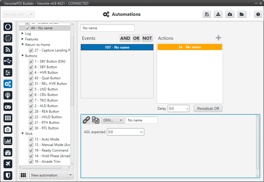
DEM calibration action
Enable/Disable Wind Estimation
This action allows the user to enable or disable the wind estimation.
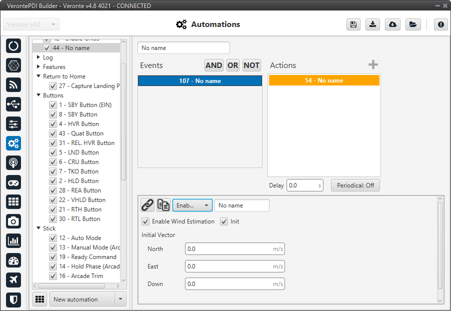
Enable/Disable Wind Estimation action
The following parameters can be configured:
Enable Wind Estimation: Enabled/Disabled.
Init: By enabling it, an initial wind vector can be set to a faster convergence of the estimation.
North, East, Down: Inital wind vector.
Envelope
This action is used to change the envelope during the flight mission. Envelopes are created in the Control Menu, see section Envelope.

Envelope action
This is useful with a hybrid platform, being possible to change the envelope when the aircraft changes its configuration. Envelopes are selected from those created previously.
FTS Activation
This action activate the flight termination system (FTS) bit.
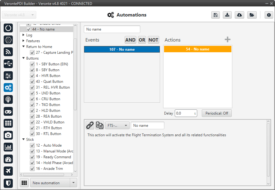
FTS Activation action
In a 4x autopilot, when two or more autopilots activate their FTS the arbiter can activate a safe system such as a parachute.
Feature
When this action is triggered, a position is stored in the desired variable. This position can be absolute or relative (in the figure below the current position of the aircraft would be saved):
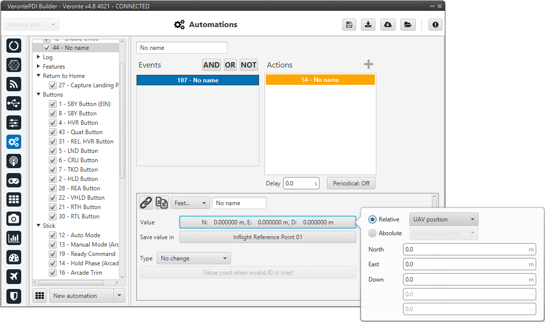
Feature action
The following options should be configured:
Value: Specified the position to be stored, this position can be absolute or relative.
Absolute: The coordinates can be set in UTM, MGRS, Decimal Degrees or Degress º ” ‘. They are indicated through the latitude, longitude and altitude (being possible to define this last one with respect to the ellipsoid, WGS84, to the sea level, MSL or to the ground, AGL).
Relative: In this case, the position of the point is relative to another point. That point could be any platform fitted with a 1x autopilot.
Save value in: The position has to be saved in an ‘Inflight Reference Point’.
Types: There are 2 types of features:
Fixed: Once the point has been generated it remains fixed.
No change: If the point has been created relative, it remains relative all the time.
Note
This option only appears when the position has been previously defined as Relative.
This action is very useful for storing the take-off point for later landing at the same place.
Format SD
Warning
This action will have irreversible effects on your 1x autopilot. Formatting the SD card will delete important and mandatory files for the correct functioning of 1x autopilot. In order to recover a formatted, please contact the support team (create a ticket in the customer’s Joint Collaboration Framework; for more information, see Tickets section of the JCF manual).
This action will format the SD card, deleting the configuration and flight logs from it.
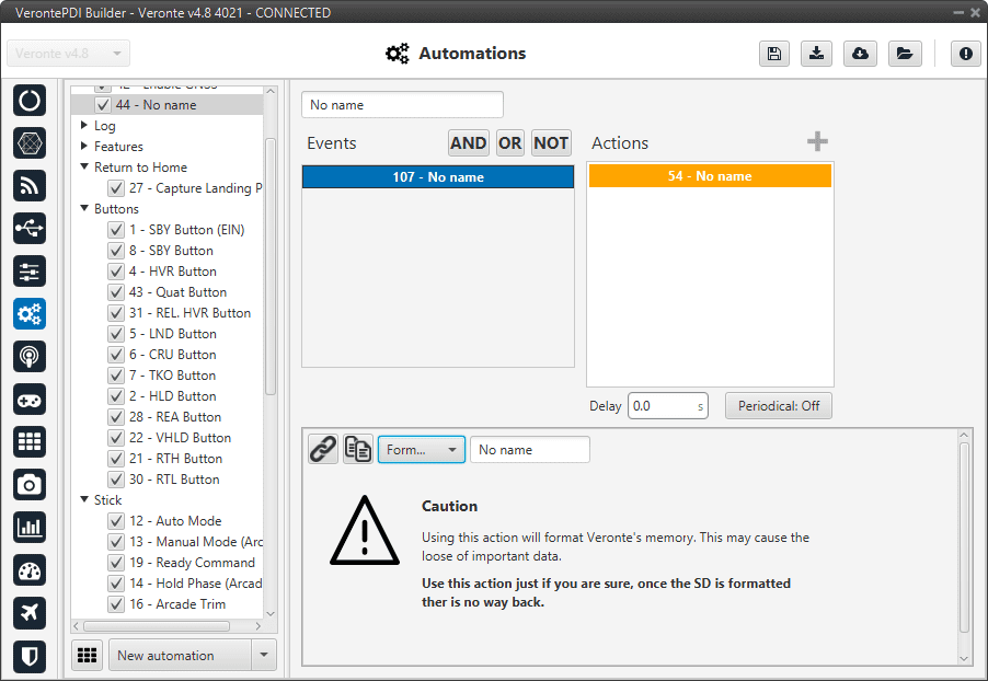
Format SD action
Go to
This action is used to make the aircraft go to a patch created by the user with the mission toolbar of Veronte Ops. For more information about the mission toolbar, take a look at the Veronte Ops manual.
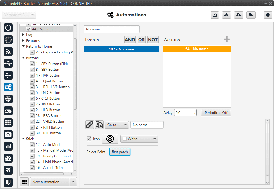
Go to action
In this action two parameters can be configured:
Select Point: To select point (patch), first define it in the Operation elements section of the UI menu.
Icon and color: It is possible to change the appearance of the point, selecting an icon from the icon list and a color, so the user can identify easily the point linked to that automation.
Once the action is triggered, the vehicle will go to that patch. If the patch is on a route, the vehicle will follow the selected patch and then it will continue the route going to its adjacent.
Mode
The flight mode is changed to the one specified in this option.
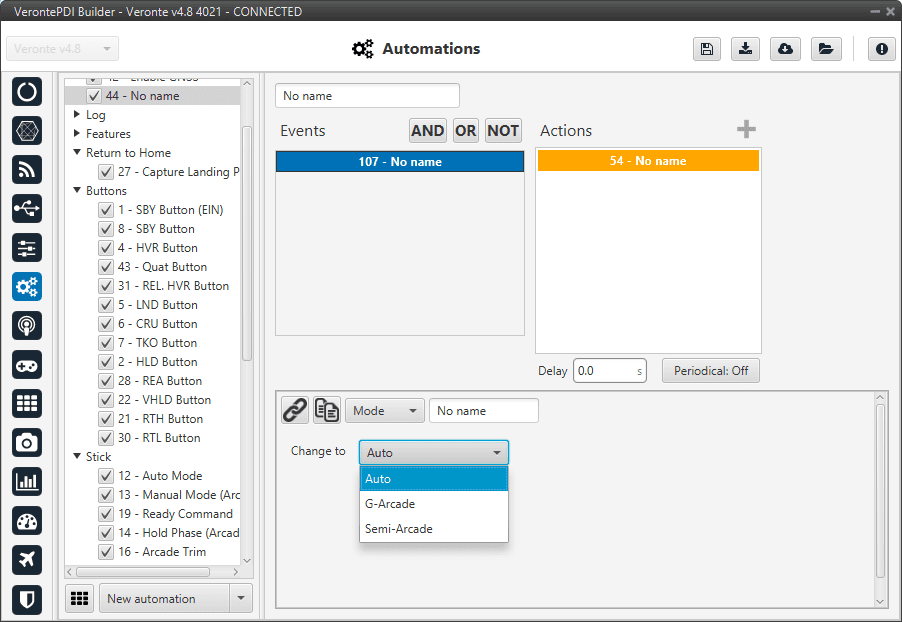
Mode action
These modes have been created previously. See section Modes, for more information about creating modes.
Navigation
This action is used to change the navigation mode used by the aircraft.
By default, the UAV uses an Internal sensor fusion algorithm, but for example, if the GPS fails, the 1x autopilot switches to inertial navigation. Since in this type of navigation, the estimation of position and velocity diverges over time, if that happens, it is advisable to switch to another type of navigation (External).
Note
This behaviour is not specific to Veronte Autopilot 1x, it is common to all inertial navigations.
The navigation without GPS will make the aircraft fly stable but it will not be possible to command a path to follow during that time, so this action can be used as a safety mode to avoid a malfunction of the system when the GPS signal is lost.
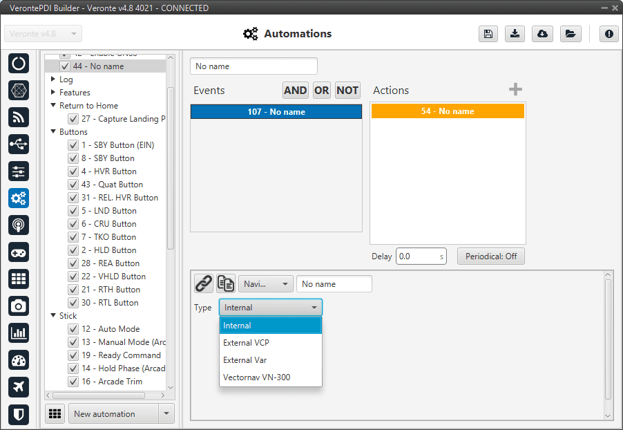
Navigation action
The options available are:
Internal: Uses internal data for navigation. Data (position, attitude, etc.) is processed into 1x unit from sensor measures.
External VCP: Uses external data for navigation. Data (position, attitude, etc.) is provided by Veronte Communication Protocol (VCP).
External Var: Uses external data for navigation. Data (position, attitude, etc.) is provided by Var.
Vectornav VN-300: Uses external data for navigation. Data (position, attitude, etc.) is provided by Vectornav VN-300. For more information, see the Vectornav VN-300 -> Integration examples section of this manual.
Obstacle avoidance
This action enables avoidance of any obstacle previously created in Veronte Ops (for more information, see Veronte Ops manual).
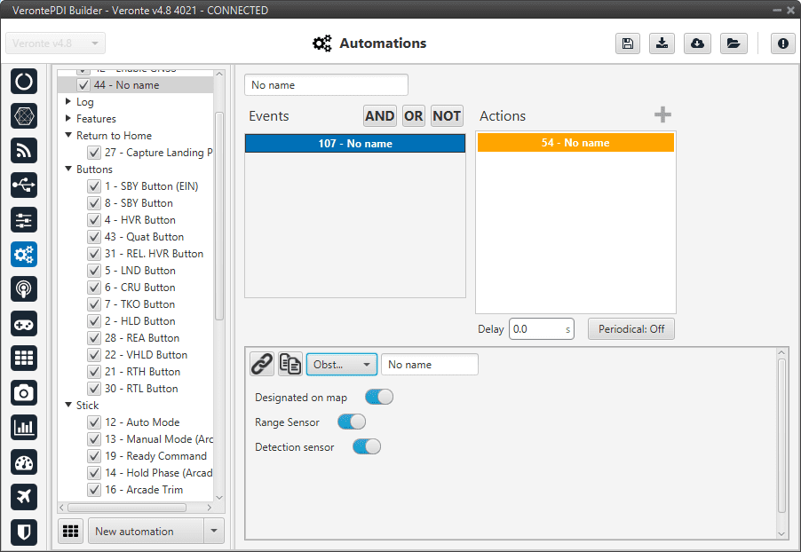
Obstacle avoidance action
Three types of obstacles can be enabled:
Designated on map: Those obstacles that appear on the map, obstacle zones and aircraft received by ADS-B.
Range sensor: Obstacles previously defined in Veronte Ops.
Detection sensor: Obstacles previously defined in Veronte Ops.
Output
This action is used to set an output value in a GPIO pin. The output pin must have been configured as a GPIO output (visit section GPIO).
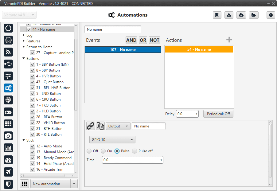
Output action
The user can select, in the drop-down menu, between a GPIO output or a virtual output. The virtual option works like a normal GPIO output, but physically this output is not in the autopilot. It is used, for example, with a CEX.
There are four possible output signals:
Off: Provides continuous 0V output.
On: Provides continuous 3.3V output.
Pulse: Provides 3.3V for the specified time and after that 0V.
Pulse off: Provides 0V for the specified time and after that 3.3V.
Periodical
This action is used to set a timer during a flight operation.
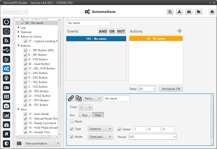
Periodical action
The following parameters are configured:
Timer: This parameter is an identifier for the timer, so it can be used in an event for another automation.
Run: The timer will start.
Stop: The timer will be stopped. Another automation should be created to run it again.
Reset: When this action is active, the timer is reset to zero before starting to measure.
Stop + Resert: The timer will be stopped and set back to zero.
Type: These available options have been explained in Automations.
Mode: The difference between fixed delay and fixed period has been explained in Automations.
For a better understanding of this action, a set of examples are detailed below with possible combinations of the different options.
Run + Distance/Time + Continuous: When the action is triggered, the timer will be started and will measure distance/time from that instant until the moment when the autopilot is turned off (or until another automation acts on the same timer).
Run + Distance/Time + Fixed Delay/Period: Once the action has been triggered, the timer will start to measure a distance/time. Each time the value indicated in Period is reached, the event linked to this timer (in another automation) will be triggered.
For example, if the user wants to take a photo each 25 meters, in a first automation, the timer should have Distance in the Type option and 25 meters in Period, then in the second automation, an event of type Timer is created (and linked with the timer before created), so each time the timer reaches 25 meters the event will be triggered and the action will be carried out.
Distance + Vector: The distance is measured in the direction indicated by the vector.
Phase
The flight phase is changed to the one selected in this action.
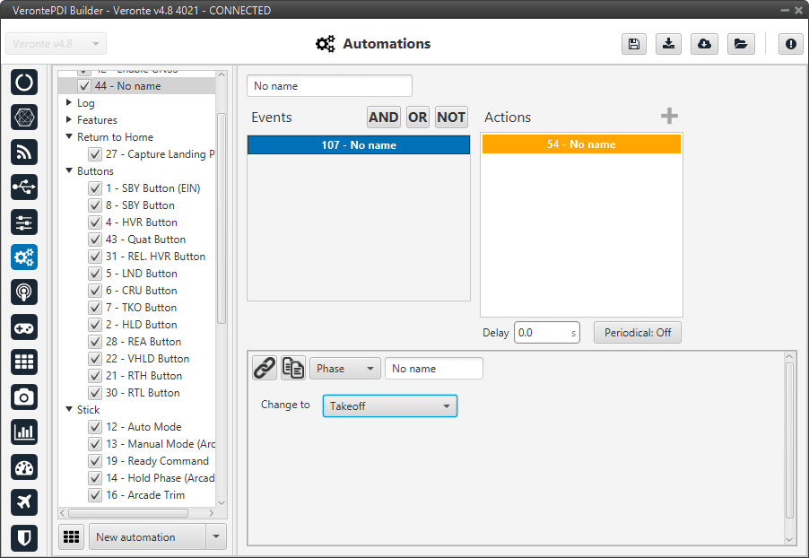
Phase action
These phases have been created previously. See section Phases, for more information about creating phases.
Ports
This action allows the user to switch between 4 pre-set configurations defined in the Ports section of the Communication menu.

Ports action
Run block program
When this action is triggered, the block program specified in the “Execute” label is executed.
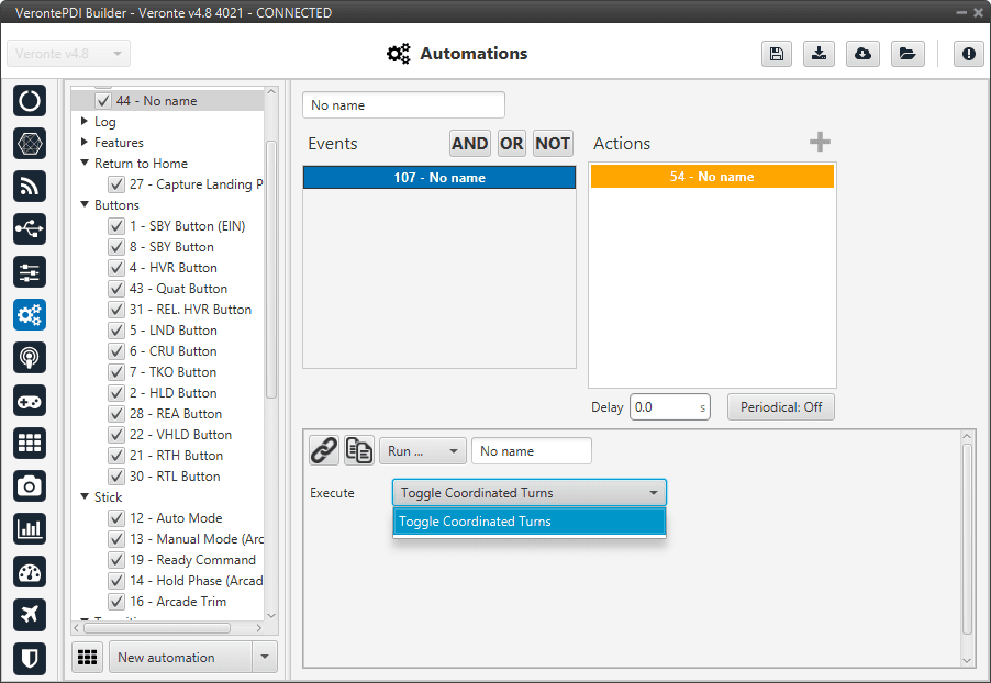
Run block program action
This action can run those programs that have the lightning icon in grey color as those programs with the lightning icon in black color run continously. For more information about programs, see section Block Programs.
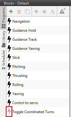
Grey lightning icon
Safety Bits
This action selects a predefined safety bits list.
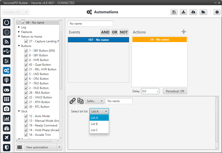
Safety Bits action
This list must be configured previously. For more information about this, see section Safety bits.
Select Arcade axis
The axes system of the aircraft is changed to one that has been previously created, see section Arcade Axis of the Control menu.
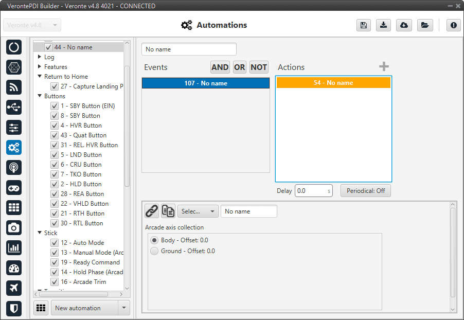
Select Arcade axis action
Stick priority
The user can switch between the two priority tables of the Stick block (for more information about the stick block, see Block Programs section). By default priority table 0 is selected when 1x autopilot starts.
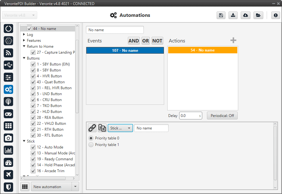
Stick priority action
Terrain obstacle
This option is used to make the aircraft climb when is reaching an altitude of zero meters, for example, when flying towards a mountain. This option can’t be activated all the time because it will not allow the aircraft to land.

Terrain obstacle action
Distance: Establish how the aircraft will climb, it can be said to be a repulsion value. High values made the platform ascent quickly. This effect is more noticeable when the aircraft is close to the ground.
Track
This action is used to configure a hover/loiter route (depending if it is a multicopter or an airplane) for the platform. Besides, there exists an option to follow a moving object.
There are 3 different options for the Track action, selecting Disabled no action will have effect on the guidance. The others are explained below.
Position
The aircraft will loiter/hover in a selected point.
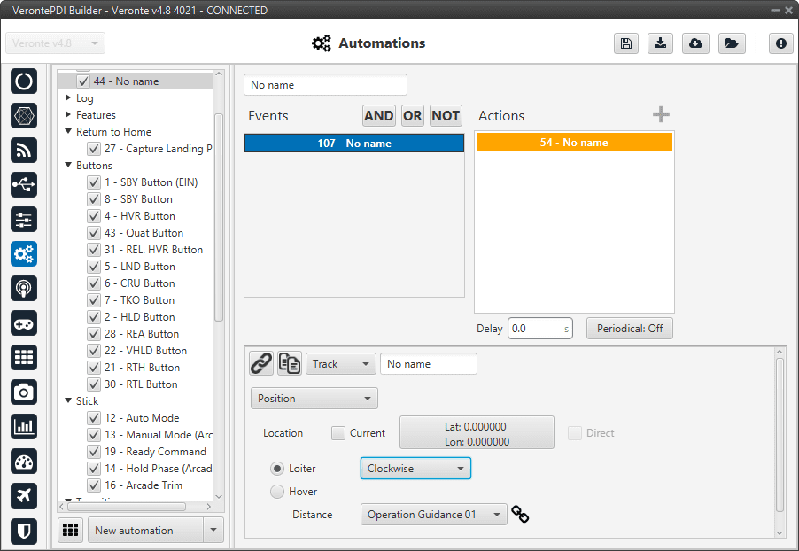
Track action - Position
The following options are available:
Location:
Selecting Current will make the platform to hover over the position that the vehicle has when this action is triggered, or loiter around that point in a circular route.
The box Longitude, Latitude allows the user to select the point where the hover/loiter will be performed.
Loiter: It is also possible to select the direction of the loiter (Auto, Clockwise and Anticlockwise).
When Hover is selected the option Direct can be enabled.
If direct is enabled, the autopilot will calculate the control actions to reach the desired point based on the position error with that point.
If direct is disabled, the autopilot will trace a path to the desired point and calculate the necessary control actions for this ‘new route’.
Distance:
Distance + Loiter: In this case, distance indicate the radius of the loiter circular route.
Distance + Hover: This option allows the user to define an acceptance radius around the position of the hover centre. If the UAV position is inside this circle, then 1x autopilot considers it is hovering correctly and will keep the position. If the centre of the hover changes its position and the UAV position is out of the hovering area, 1x will fly to the hovering centre, and once it is inside the circle, the hover will start.
Follow Leader
The platform will follow a moving object.
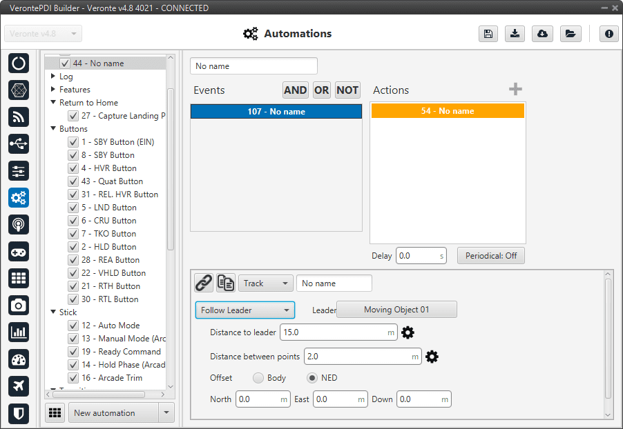
Track action - Follow Leader
In this action the following parameters can be configured:
Leader: Here is selected the object to follow, e.g. Moving Object.
Distance to leader: Distance to leader over trajectory.
Distance between points: Leader route is generated by points separated by the distance specified here.
Offset: User can establish offset parameters related to trajectory in Body or NED coordinates.
Note
To configure correctly this automation, user has to follow the next steps:
Configure Telemetry in Air and Ground units.
Configure the automation as desired.
User Log
An entry, previously configured in User Log -> Telemetry section, is added to the on-board log.
User Log action
Variable
This action allows the user to select variables and save them in user variables.
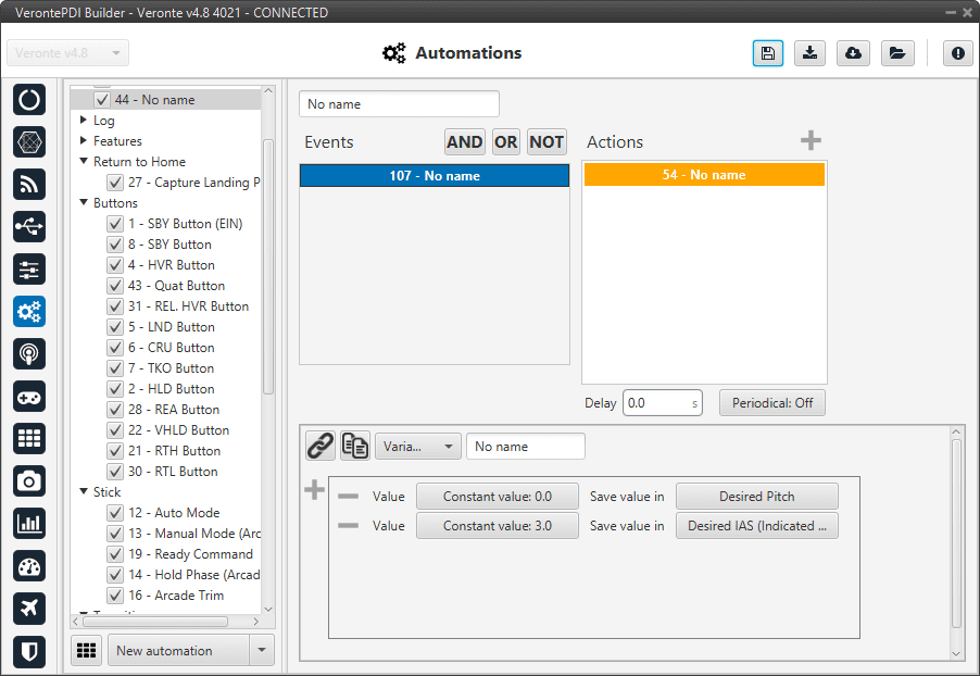
Variable action
Yaw
When this action is triggered the actual yaw can be commanded.
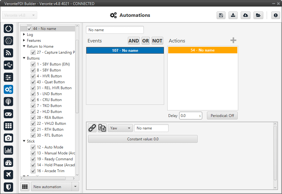
Yaw action
This action is useful when flying without a magnetometer, as the user can establish the current yaw value when it is known.