Troubleshooting
Communication lost with internal Digi radio
Most of the time, the communication between Autopilot 1x and Digi radio is lost due to a change in its baudrate.
In 1x PDI Builder it is set to 115200 by default, however, in Digi radios the factory default baudrate at reset is 9600.
To recover communication, try changing the baudrate on one of them to match.
Go to Communications menu \(\rightarrow\) Veronte LOS section.
Set the Baudrate on Veronte LOS to 9600.
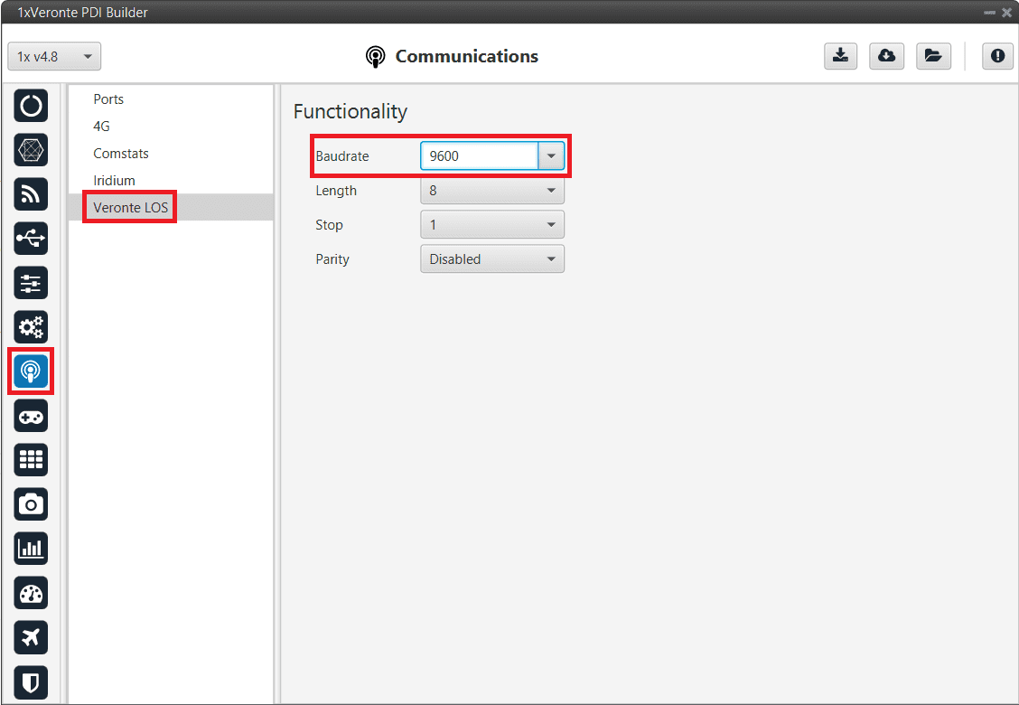
Veronte LOS baudrate
Check the steps described in the Digi internal radio -> Integration examples section to see if the module is now detected in XCTU software.
Then, if desired, the user can change the radio baudrate to 115200 and after that also change it for Veronte Autopilot 1x.
Debug serial messages transmission
To check that the transmission of serial messages is being carried out correctly, the user can view what is being sent in the 1x PDI Calibration software hyperterminal. To do this:
In 1x PDI Builder
Go to Input/Output menu \(\rightarrow\) I/O Setup section.
Connect the RS custom message producer (where the message is configured) to a Tunnel with App2 address. In this case the message is configured in the RS custom message 1 producer.
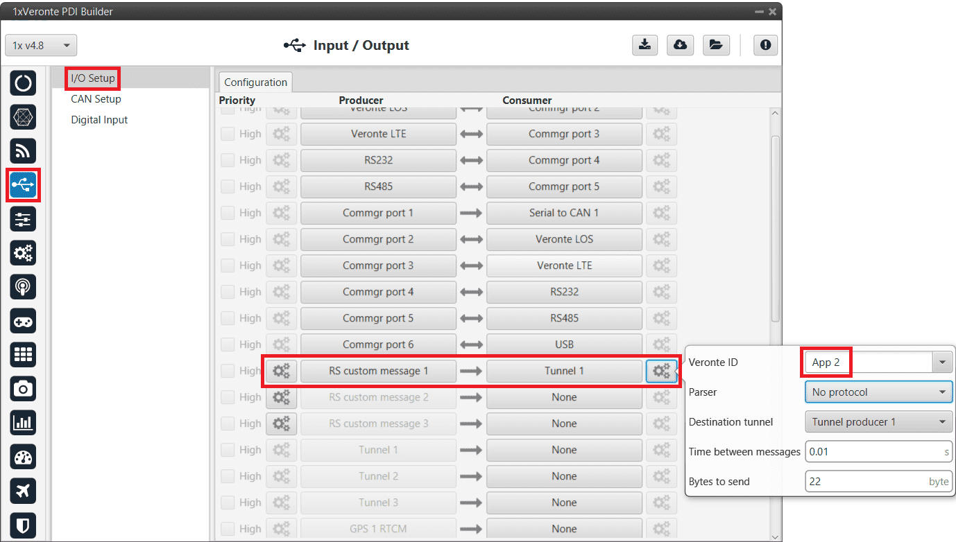
RS cutom message \(\rightarrow\) Tunnel
In 1x PDI Calibration
Go to Terminal tab.
Click on Agree:
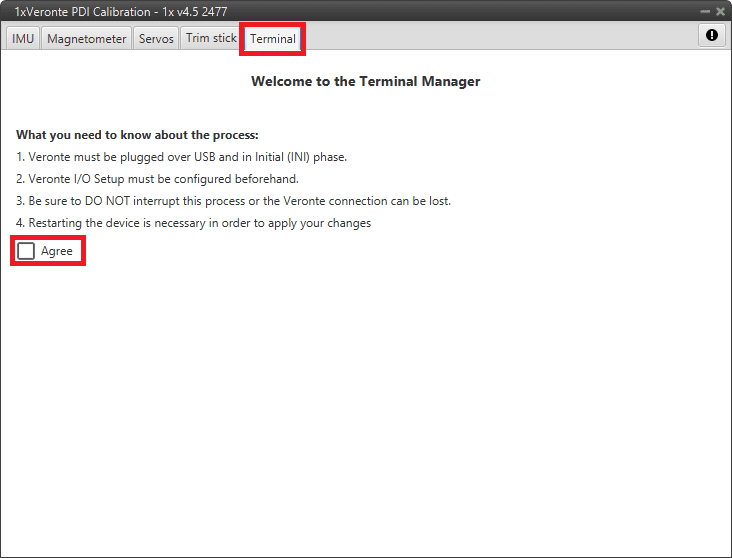
Terminal tab
Next, select the Tunnel 1 (this is the one that has been configured in 1x PDI Builder) and click on Launch:
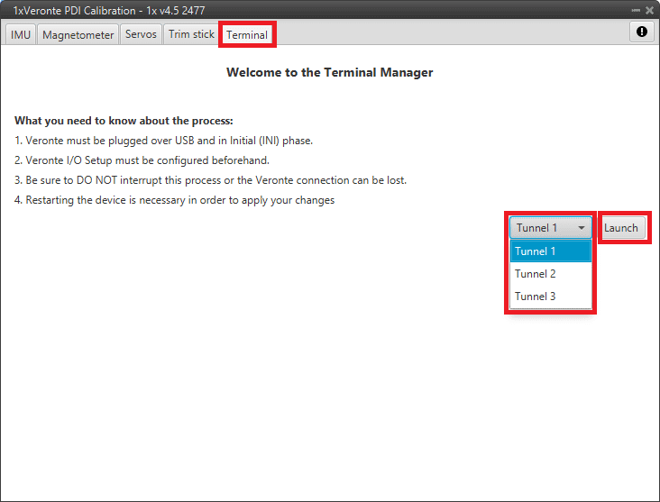
Terminal tab - Tunnel selected
The tunnel console should open and the user will be able to view the message being sent:
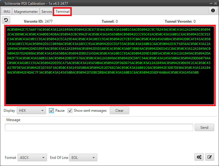
Tunnel console
For more information on the Terminal configuration, please refer to the Terminal section of the 1x PDI Calibration user manual.
Maintenance mode
The user can simply enter maintenance mode via 1x PDI Builder by clicking on the “Normal mode” button in the initial menu. In addition, exiting maitenance mode is the same process.
Below is an example of how to do this:
Enter/Exit maintenance mode
Maintenance mode (loaded with errors)
The following error message may appear when trying to save a change or import a configuration.
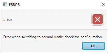
Error message
Therefore, Veronte Autopilot 1x will be in ‘Maintenance mode (loaded with errors)’:
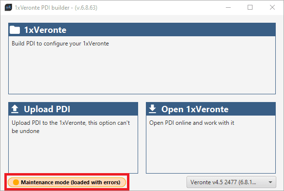
Maintenance mode (loaded with errors)
To check what the source of the problem is, the user can consult the Veronte Ops Platform panel, which will show what the PDI Error is. For more information on this panel, see Platform panel section of the Veronte Ops user manual.
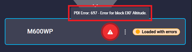
PDI Error - Veronte Ops
Then, it is possible to access the Autopilot 1x configuration to fix this error.
Tip
If the PDI error is related to a migration, it is usually caused by the selection of accelerometer, gyroscope and magnetometer sensors.
In addition, a list of all PDI Errors can be accessed in the List of PDI errors section of the 1x Software Manual.
Radios paired but 1x air unit not showing
If the radios of both Autopilots 1x, air and ground unit, are paired but the air unit does not appear connected in Veronte Link, check the Ports configuration on the 1x ground unit. To do this:
Go to Communications menu \(\rightarrow\) Ports section, and it should be similar to the configuration shown in the figure below:
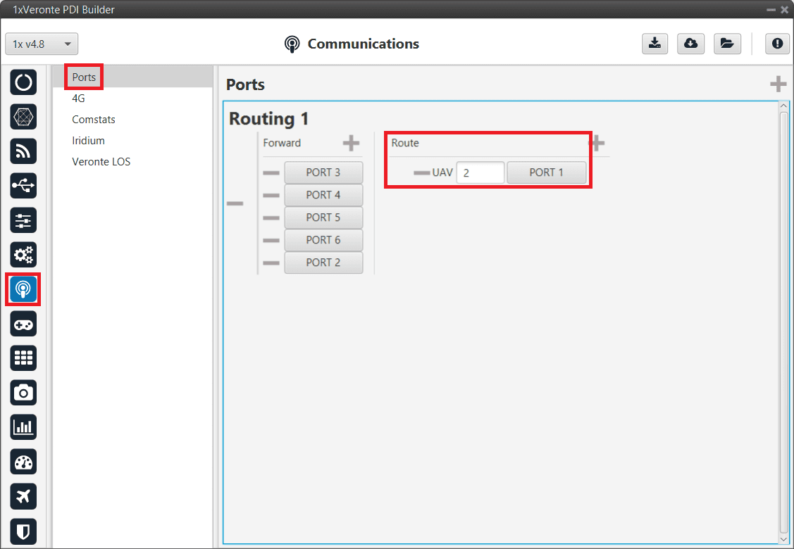
1x ground unit - Ports configuration
Reducing GNC Task frequency
400 Hz is the maximum possible frequency, but can only be used in simple configurations, in other cases it is advisable to reduce it to 250-300 Hz.
To find out if the frequency needs to be reduced in the user configuration, check the GNC Task Average CPU Ratio variable.
For correct operation, this variable should be at approximately 60-70%. If it reports a higher value, the frequency must be lowered.
Trajectory Overshoot
If the user observes significant meandeling or overshoot in the mission path, this can be reduced by modifying the gains of the guidance PIDs:
Reducing the proportional gain.
Ensure that the integral gain is 0.
Guidance error accumulates and leads to increasing overshoot, as can be seen in the following example:
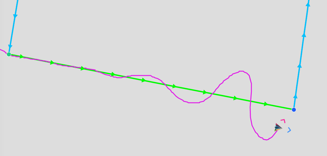
Trajectory overshoot
Unstable communication with CEX/MEX
If communication with a CEX/MEX appears to be OK, but suddenly fails, i.e. there is unstable communication between the devices, it may be because Serial to CAN and CAN to Serial communications have not been marked as High priority. In order to do this:
Go to Input/Output menu \(\rightarrow\) CAN Setup section \(\rightarrow\) Coniguration tab, and mark Serial to CAN and CAN to Serial communications as High priority (with the Priority checkbox):
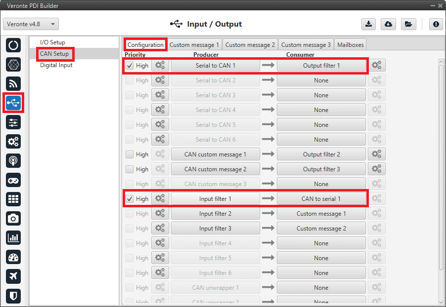
CAN Setup - High priority