Veronte products
Autopilot 4x
To establish on a Veronte Autopilot 4x version 1.8 the communication between Autopilots 1x and Arbiters via CAN, the following connection is required:
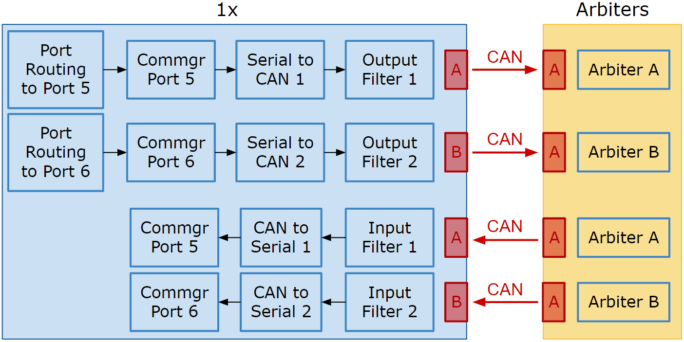
Communication diagram 1x - Arbiters
Follow the steps below to make this configuration:
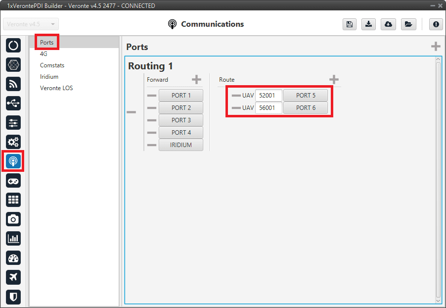
Go to Communications menu \(\rightarrow\) Ports section.
Remove Port 5 and 6 from the Forward group and Add Port 5 and 6 to the Route group, with target Arbiters’ Address:
Address of Arbiter A: 50 000 + Serial number
Address of Arbiter B: 54 000 + Serial number
Routing configuration
Note
This is just an example, users can choose Ports other than 5 and 6.
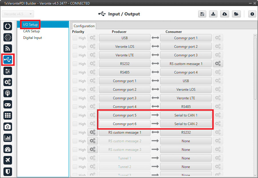
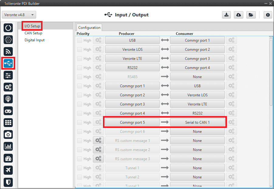
Go to Input/Output menu \(\rightarrow\) I/O Setup section.
Connect Commgr Port 5 to Serial to CAN 1 consumer and Commgr Port 6 to Serial to CAN 2 consumer:
I/O Setup - Serial to CAN
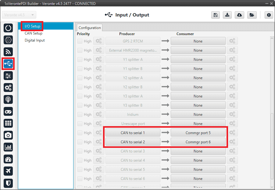
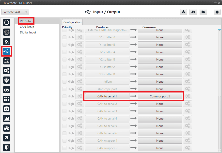
Then, connect CAN to Serial 1 to Commgr Port 5 and CAN to Serial 2 to Commgr Port 6:
I/O Setup - CAN to Serial
Note
This is just an example, users can choose Serial to CAN and CAN to Serial other than 1 and 2.
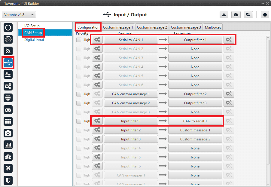
Go to Input/Output menu \(\rightarrow\) CAN Setup section \(\rightarrow\) Configuration tab.
Connect Serial to CAN 1 to Output filter 1 and Serial to CAN 2 to Output filter 2.
In addition, connect Input filter 1 to CAN to Serial 1 and Input filter 2 to CAN to Serial 2:
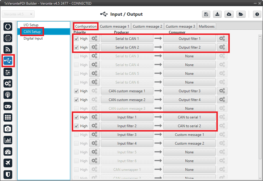
CAN Setup
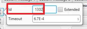
Set for both Serial to CAN 1/2 the same CAN ID: 1302.
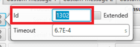
CAN Setup - Serial to CAN 1/2 configuration
Select for Output filter 1 the CAN A, as this is the CAN of 1x Autopilot that is connected to Arbiter A:
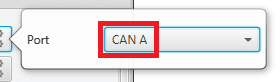
CAN Setup - Output filter 1 configuration
Select for Output filter 2 the CAN B, as this is the CAN of 1x Autopilot that is connected to Arbiter B:
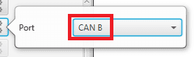
CAN Setup - Output filter 2 configuration
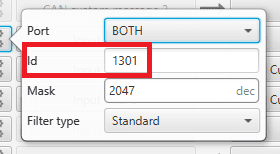
Configure both Input filter 1/2 with CAN ID:1301.
Select for Input filter 1 the CAN A, as this is the CAN of 1x Autopilot that is connected to Arbiter A:
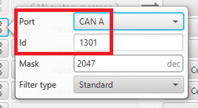
CAN Setup - Input filter 1 configuration
Select for Input filter 2 the CAN B, as this is the CAN of 1x Autopilot that is connected to Arbiter B:
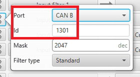
CAN Setup - Input filter 2 configuration
Note
This is just an example, users can choose Input filter and Output filter other than 1 and 2.
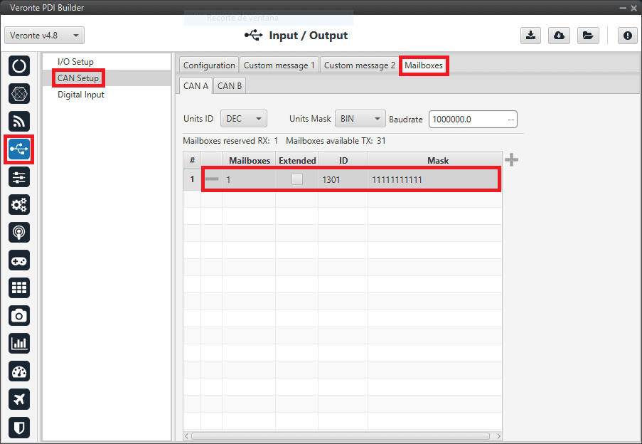
Go to Input/Output menu \(\rightarrow\) CAN Setup section \(\rightarrow\) Mailboxes tab.
Set the Baudrate for both CANs, CAN A: 1 000 000 and CAN B: 500 000.
Configure at least 10 reception mailboxes with ID 1301 for both CAN A and B:
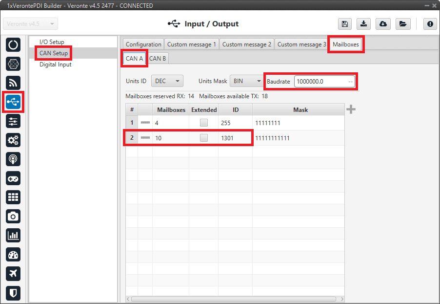
Mailboxes - CAN A configuration
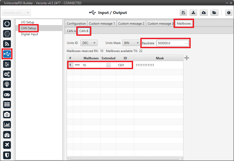
Mailboxes - CAN B configuration
CEX/MEX
As it is sometimes not possible to connect a CEX/MEX directly to the PC in order to configure it (access CEX/MEX PDI Builder), the Veronte Autopilot 1x is connected to the computer and a connection is made between CEX/MEX and Veronte Autopilot 1x via CAN.
To be able to communicate with CEX/MEX via CAN, the following connection is necessary:
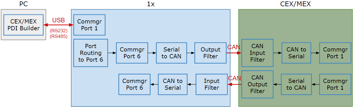
Communication diagram 1x - CEX/MEX
Note
1x usually has this configuration by default, but check it out.
As the steps to be performed in CEX PDI Builder and MEX PDI Builder is exactly the same, only the steps for one of them will be detailed. The interface may differ slightly, but the configuration is the same.
Follow the steps below to make this configuration:
1x PDI Builder side
Go to Input/Output menu \(\rightarrow\) I/O Setup section.
Check the connection between the computer and the 1x (usually via USB, but RS232 and RS485 are also possible).
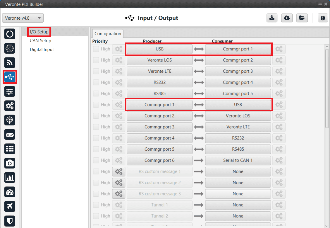
1x - USB communication
Go to Communications menu \(\rightarrow\) Ports section.
Remove Port 6 from the Forward group and Add Port 6 to the Route group, with target CEX’s Address:
\(\Rightarrow\) Address = 44000 + Serial number.
The CEX address must be in the range 45000 - 49999.
Note
For MEX, the address should look like this:
Address = 42000 + Serial number.
The MEX address must be in the range 43000 - 43999.
If the theorical address does not work, 999 (unknown) can be used as sometimes the address has not been set in CEX/MEX.
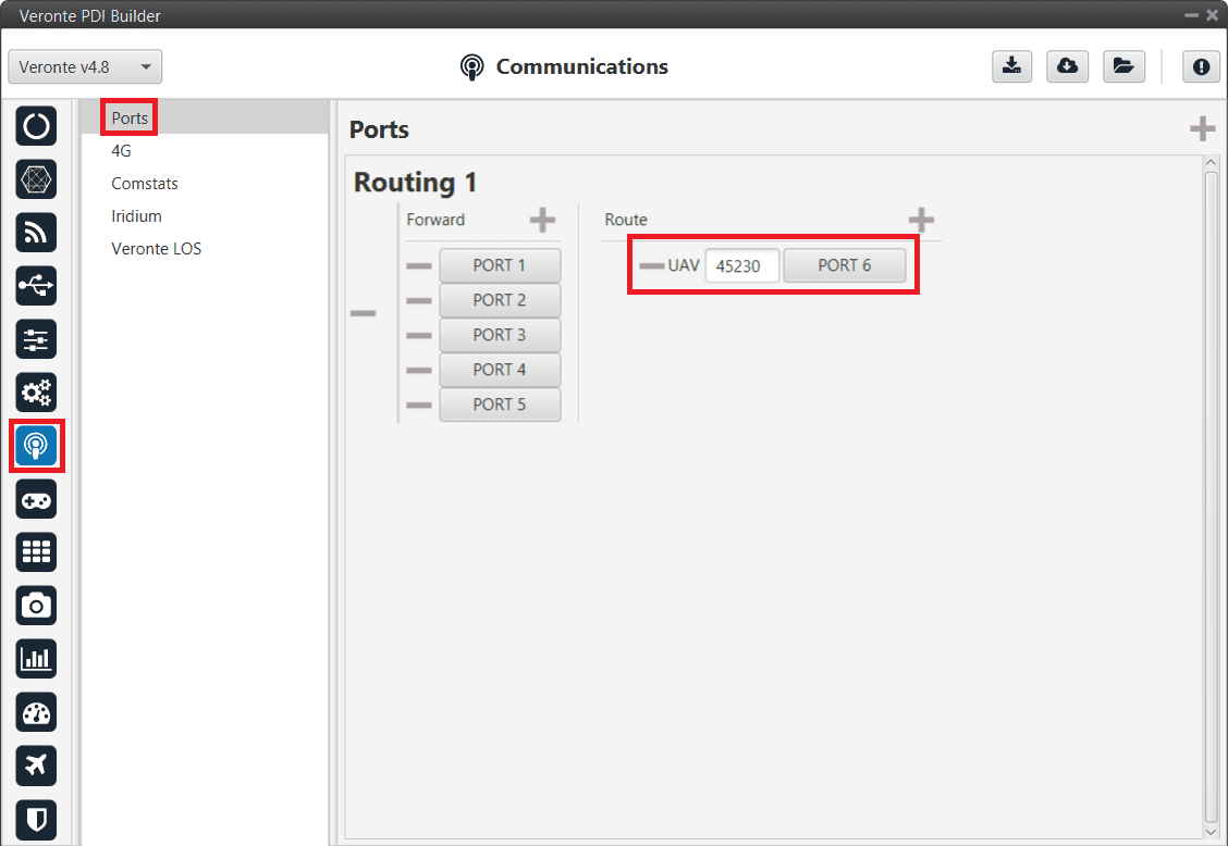
1x - Routing
Go to Input/Output menu \(\rightarrow\) I/O Setup section.
Connect Commgr Port 6 to Serial to CAN 1 consumer:
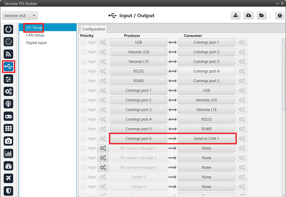
1x - I/O Setup - Serial to CAN
Then, connect CAN to Serial 1 to Commgr Port 6:
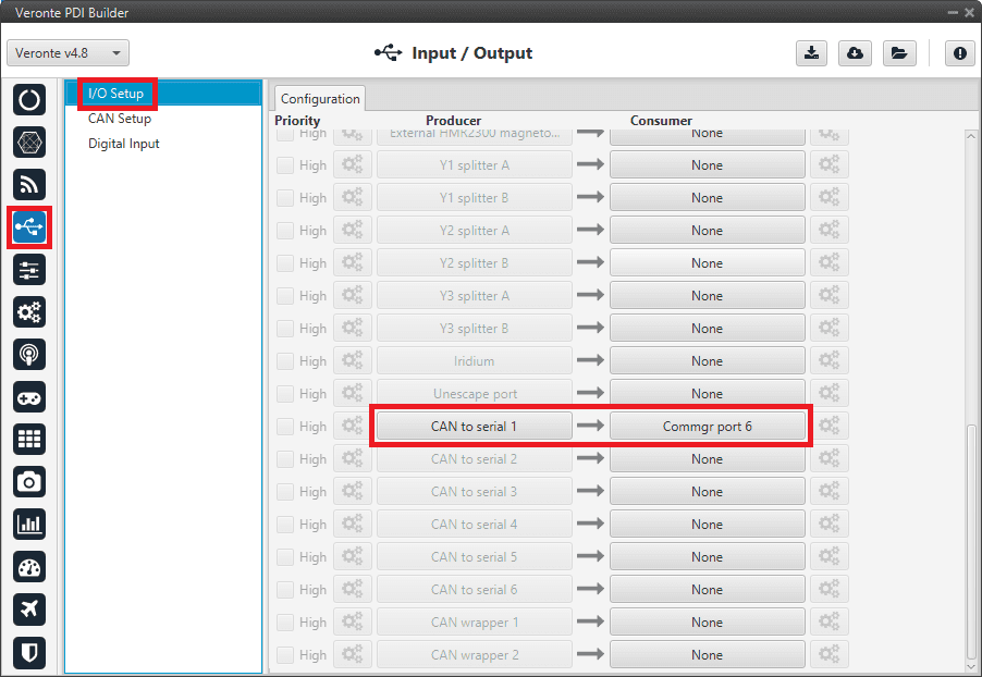
1x - I/O Setup - CAN to Serial
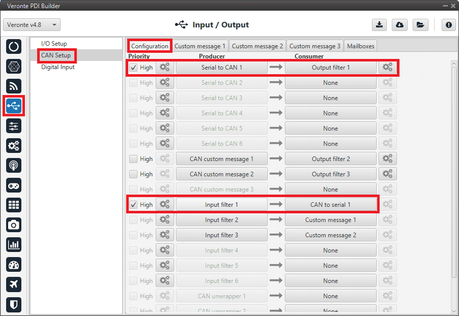
Go to Input/Output menu \(\rightarrow\) CAN Setup section \(\rightarrow\) Configuration tab.
Connect a Serial to CAN with the right Id (CAN ID 1302) to an Output filter.
In addition, connect an Input filter with the right Id (CAN ID 1301) to a CAN to Serial:
Warning
For correct communication, mark both as High priority (with the Priority checkbox).
1x - CAN Setup
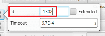
1x - CAN Setup - Serial to CAN configuration
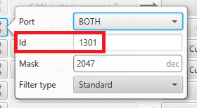
1x - CAN Setup - Input filter configuration
Go to Input/Output menu \(\rightarrow\) CAN Setup section \(\rightarrow\) Mailboxes tab.
Finally, configure the reception mailbox with ID 1301, assign at least 4 mailboxes:
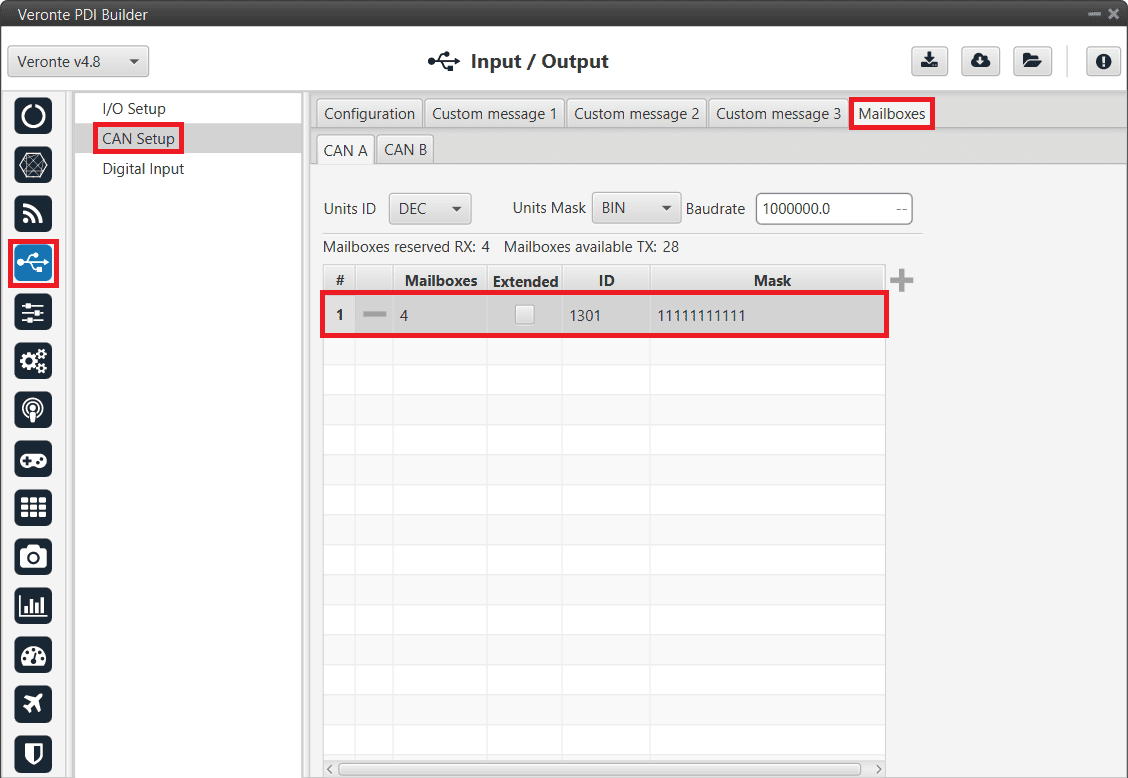
1x - Mailboxes configuration
CEX PDI Builder side
Note
This part is already built for CEX default configuration, but the user can check it.
Go to Input/Output menu \(\rightarrow\) CAN I/O section \(\rightarrow\) Configuration tab.
Connect a CAN Input filter with the right CAN Address (CAN ID 1302) to CAN to Serial 1.
In addition, connect Serial to CAN 1 with the right CAN Address (CAN ID 1301) to a CAN Output filter port:
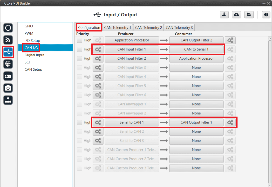
CEX - CAN I/O
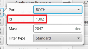
CEX - CAN I/O - Input filter configuration
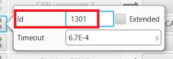
CEX - CAN I/O - Serial to CAN configuration
Go to Input/Output menu \(\rightarrow\) I/O Setup section.
Connect CAN to Serial 1 to any Commgr Port 1 in CEX.
In addition, connect Commgr Port 1 to Serial to CAN 1 consumer:
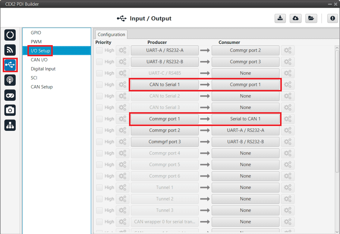
CEX - I/O Setup
Go to Input/Output menu \(\rightarrow\) CAN Setup section.
Finally, configure the reception mailbox with ID 1302, assign at least 4 mailboxes:
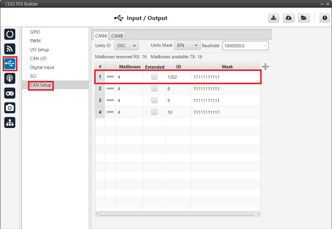
CEX - CAN Seup (Mailboxes) configuration
MC01
In order to communicate a Veronte Autopilot 1x with a MC01 via CAN, the following connection is required:
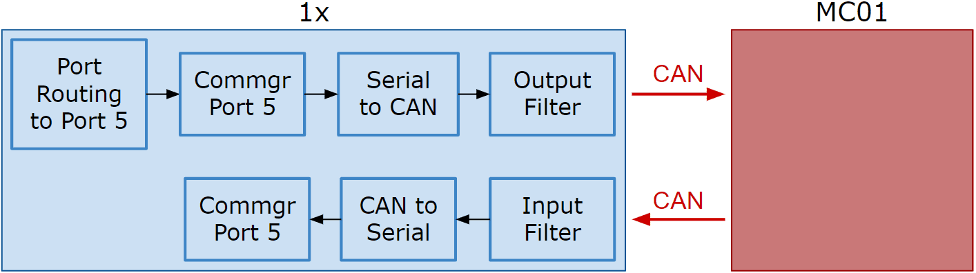
Communication diagram 1x - MC01
The following steps explain how to configure the communication between a 1x Autopilot and a MC01.
MC01 PDI Builder side
By default, MC01 is configurated with a connection Serial to CAN, with the following Standard CAN IDs:
Tx CAN Id: 1301
Rx CAN Id: 1302
1x PDI Builder side
Go to Communications menu \(\rightarrow\) Ports section.
Remove Port 5 from the Forward group and Add Port 5 to the Route group, with target MC01’s Address. This address must be chosen in the destination path of the MC01 (40117 for the example).
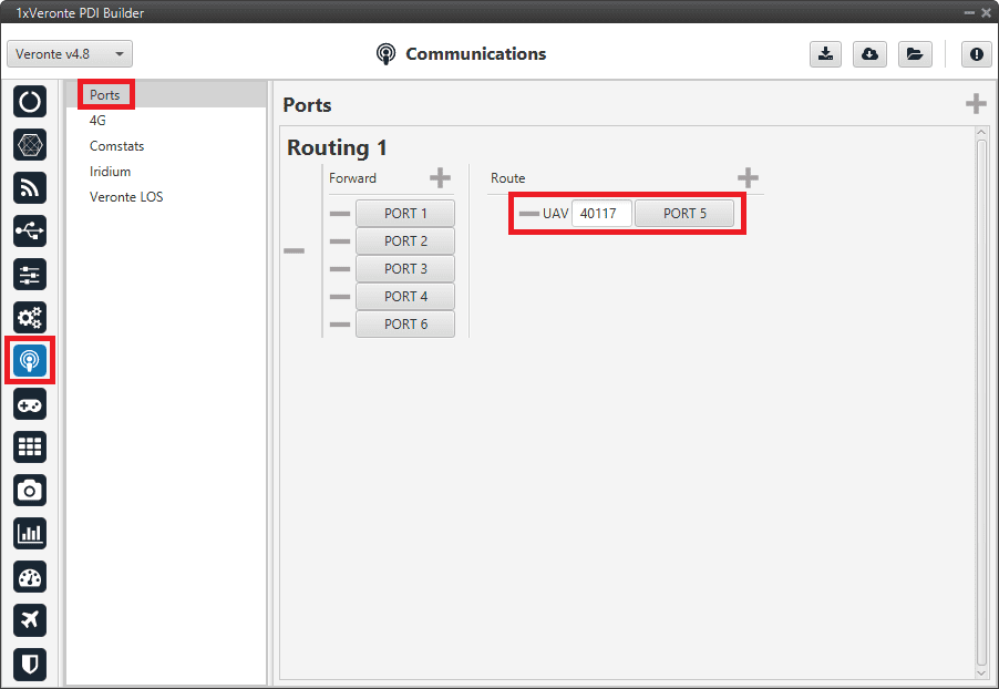
Routing configuration
Go to Input/Output menu \(\rightarrow\) I/O Setup section.
Connect the Commgr Port 5 to the Serial to CAN 1.
I/O Setup - Serial to CAN
Then, connect CAN to Serial 1 to Commgr Port 5:
I/O Setup - CAN to Serial
Go to Input/Output menu \(\rightarrow\) CAN Setup section \(\rightarrow\) Configuration tab.
Connect a Serial to CAN with the right Id (CAN ID 1302) to an Output filter.
In addition, connect an Input filter with the right Id (CAN ID 1301) to a CAN to Serial:
CAN Setup
CAN Setup - Serial to CAN configuration
CAN Setup - Input filter configuration
Go to Input/Output menu \(\rightarrow\) CAN Setup section \(\rightarrow\) Mailboxes tab.
Finally, configure the reception mailbox with ID 1301, assign at least 1 mailbox:
Mailboxes configuration
VSE (Veronte Stick Expander)
To configure the VSE in 1x PDI Builder it is only needed to follow the steps explained in the Ground unit configuration in the General case - PPM stick integration section of this manual.
In the step 1 of that explanation, there is already a transmitter configured with the required configuration of the VSE, users will find it as Brand: Embention and Model: Stick Expander.