Servos
The user can configure any actuator compatible with the communication interfaces.
PWM
The following steps explain how to configure a PWM servo in Veronte Autopilot 1x.
Connect the servo according to the manufacturer’s documentation and follow the Hardware installation - Electrical section of the 1x user manual to connect it to the 1x autopilot.
Go to Connections menu \(\rightarrow\) PWM section.
Select and configure the PWM pins where the servos are connected. Set the frequency according to the manufacturer’s specifications.
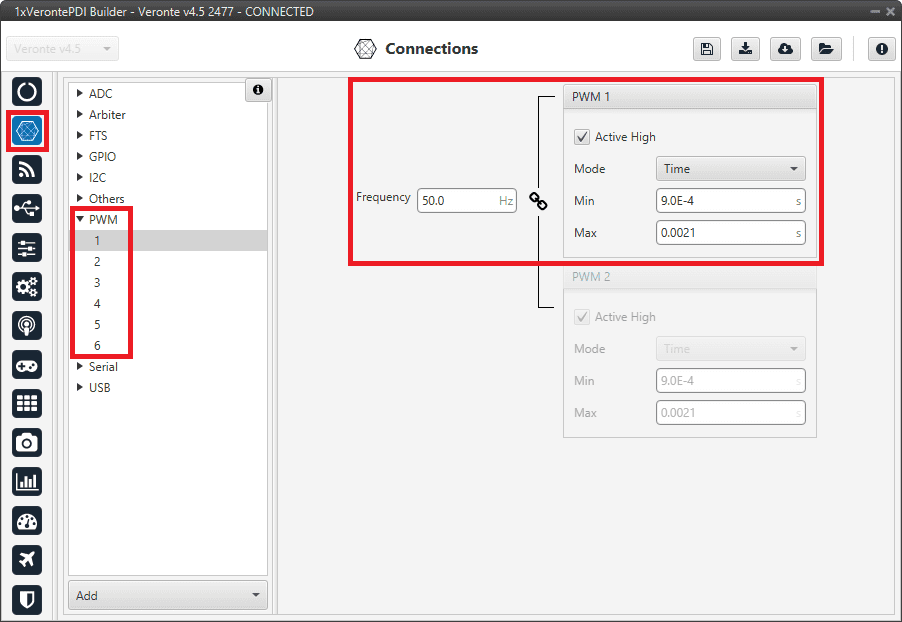
PWM connection configuration
Caution
If there is no PWM tab or the PWM pin where the servo is connected is not shown on the interface, it must be because they are configured as GPIO. For this, refer to PWM section of this manual.
Go to Block Programs menu.
Create a program to make the necessary connection to the servo blocks.
Usually the user has a Control to servo program where the servo blocks are implemented.
Configure the Actuator block connecting PWM block as Pulse and Actuator Outputs as Servo:
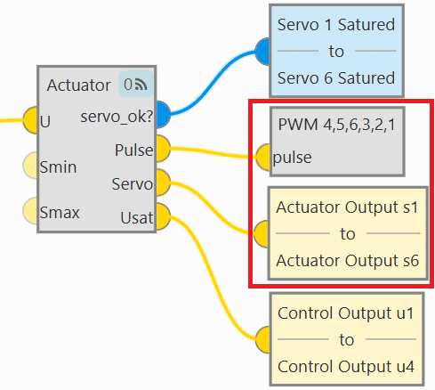
Block programs connection
Assign a given PWM to a given actuator output.
The assignment is done automatically in the order in which they are configured in the blocks. That is, the first PWM will relate to the first actuator output, which does not necessarily mean that PWM 1 is assigned to Actuator Output s1.
In this example, the PWMs are assigned to the actuator outputs as shown in the following figure:
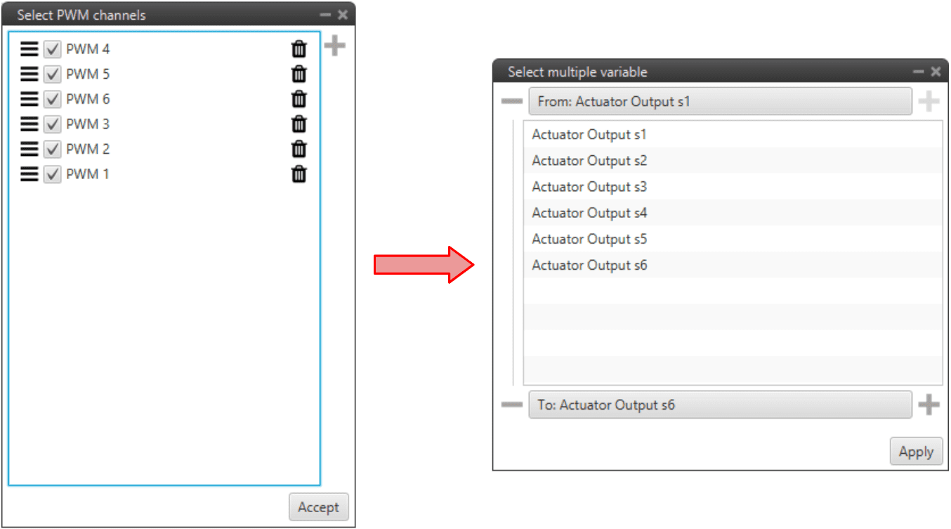
Block programs configuration
Note
For instance, PWM 6 is assigned to Actuator Output s3.
For more information on Actuator and PWM blocks, see Actuator block and PWM block of Block Programs section.
Serial
Serial servos are configured differently than PWM servos as the protocol of a serial device must be defined with serial custom messages.
In this case a PWM variable must be sent through a serial interface.
Volz DA26 - RS485
Firstly, the following wiring connection is recommended for a RS485 connection between Volz DA26 servos and Veronte Autopilot 1x:
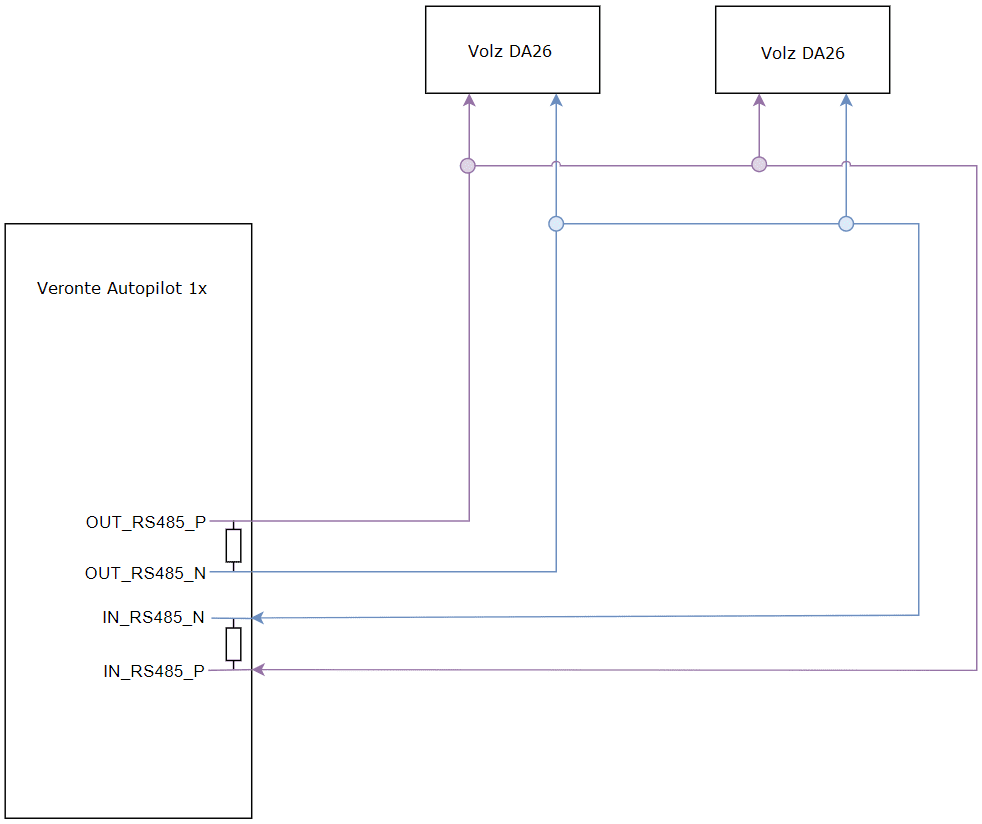
Volz DA26 - Veronte Autopilot 1x wiring connection
The above diagram is made for the case where 2 Volz DA26 servos are connected, however, the connection is the same in case the user wants to connect only one or as many servos as the bus allows.
Follow the steps below to configure a Volz DA26 servo via RS-485.
Go to Input/Output menu \(\rightarrow\) I/O Setup section.
Bidirectionally connect the RS485 port to a RS custom message, in this example RS custom message 1 is used:
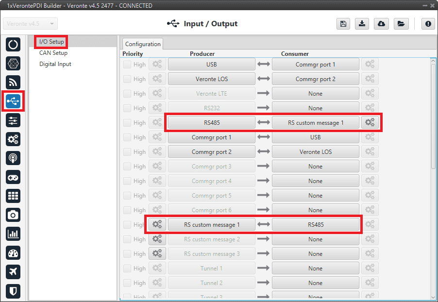
RS485 \(\leftrightarrow\) RS custom message 1
Configure the RS custom message 1 producer by defining the protocol specified by the manufacturer:
Note
As the RS-485 is a Half Full duplex serial port, Veronte Autopilot 1x needs to leave this serial bus free for a certain time in order to receive the servo response. This is done by setting the Delay parameter.
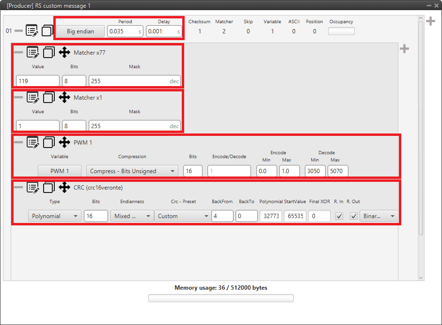
RS custom message 1 - Manufacturer’s communication protocol
Endianness: Big endian
Period: 0.035
Delay: 0.0015
Matcher x77: Silent mode command (0x77).
Value: 119
Bits: 8
Mask: 255
Matcher x1: Servo interface Id = 1. The Id will be different for each servo and/or interface.
Value: 1
Bits: 8
Mask: 255
PWM 1: PWM is the variable that carries the information that has to be applied to the servo. Therefore, it must be included in the message.
Variable: PWM 1
Compression: Compress - Bits Unsigned
Encode: 0 / 1
Decode: 3050 / 5070
CRC (Custom): A Checksum is needed to complete the communication protocol.
Type: Polynomial
Bits: 16
Endianness: Mixed endian
CRC - Preset: Custom
BackFrom: 4
BackTo: 0
Polynomial: 32773
Start Value: 65535
Final XOR: 0
Note
For more information on checksum, see Checksum (CRC) explanation - I/O section of this manual.