Altimeters
Lidar
The integration between Veronte Autopilot 1x and a lidar is performed using a variety of interfaces depending on the lidar device. The most common interfaces are I2C or analog although serial or CAN bus can also be used if the lidar is compatible.
ADC lidar
An ADC lidar changes the voltage depending on the measured distance and therefore the connection to the Autopilot 1x is made using the ADC pins (see section Hardware installation - Electrical of the 1x user manual).
Once connected to 1x autopilot, the value can be monitored in 1x PDI Builder by using the variables ADC1 to ADC5. For pin ANALOG_1 the correspondent ADC variable in 1x PDI Builder is ADC1.
Go to Connections menu \(\rightarrow\) ADC 1 section.
Click on ‘Create new program’:
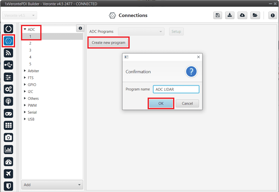
Create ADC program
Go to Block programs menu.
Configure the following operation (for more information about blocks, see Block Programs):
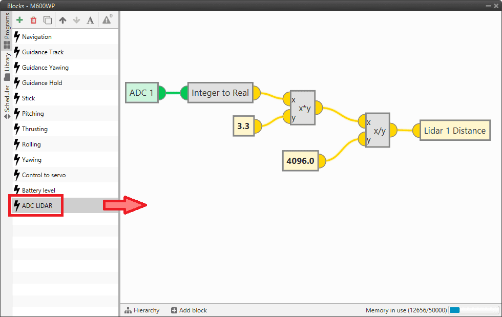
Lidar operation
After implementing the operation the variable Lidar 1 Distance will represent the distance measured by the lidar.
Note
As 4x Autopilot can read up to 36 V per each ADC, the \(3.3\) value of the ADC program must be changed to \(36\) if applicable.
I2C lidar
I2C lidars are configured slightly differently.
Connect the lidar following the pinout provided by the manufacturer and connect it to the Veronte Autopilot 1x I2C bus following the Hardware installation - Electrical section of the 1x user manual.
In this case it is not needed to transform the lidar readings, the readings will be reported directly in the selected lidar distance variable.
Go to Sensors menu \(\rightarrow\) Lidar section.
Enable Lidar 1
Select the desired Lidar from the drop-down menu
Set the I2C address
More information on the available lidar options can be found in the Lidar section of this manual.
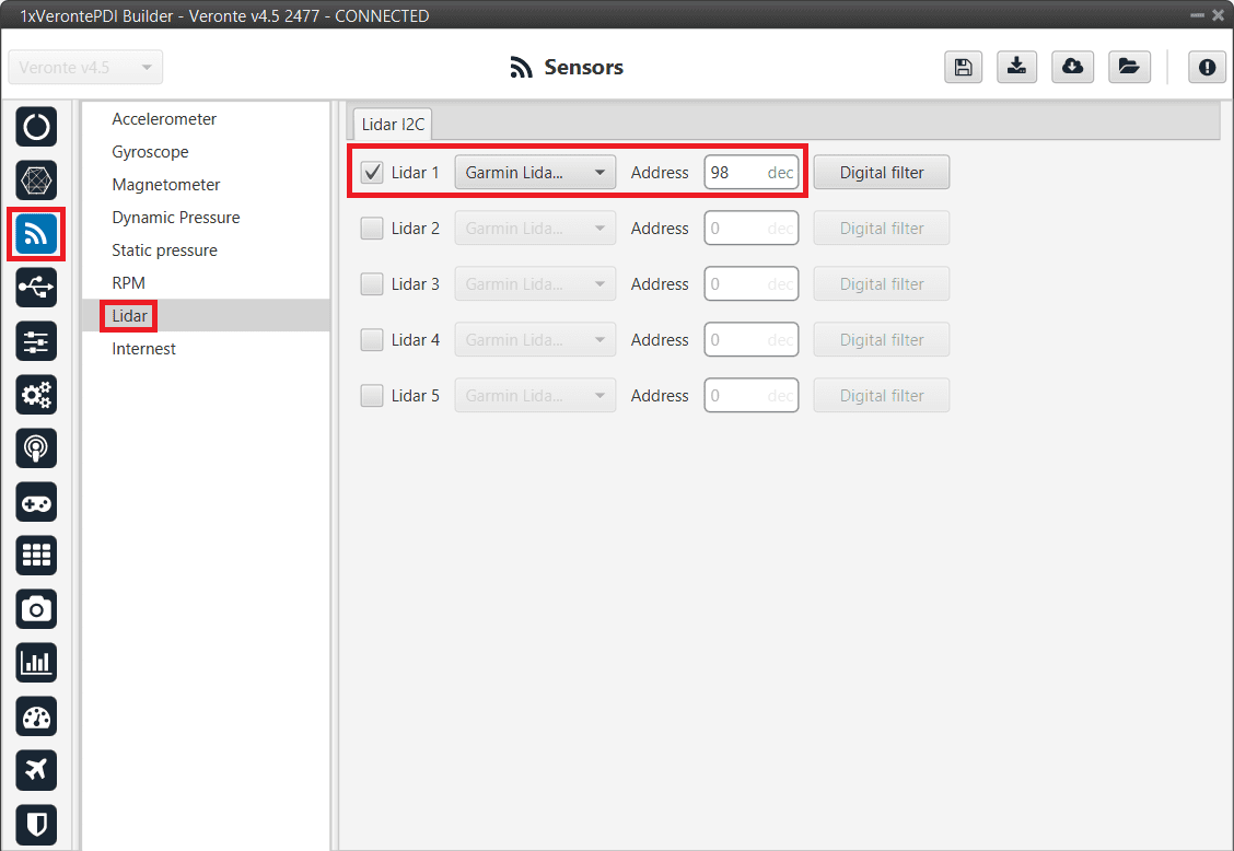
I2C Lidar
Warning
I2C address will be different for different devices make sure to define it properly by checking the manufacturer documentation.
Using lidar readings
Once the information provided by a lidar sensor is stored in a system variable as Lidar Distance via an ADC reading, I2C, serial or CAN, the user has to set how this data will be considered. Common uses are: to consider the lidar data as external sensor or to trigger an action based on a predefined event.
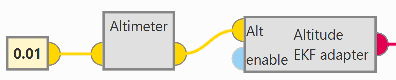
Altimeter configuration: The following operation must be configured in the Block Programs menu to consider the lidar measurement as an EKF input.
Altimer connection - Block Programs
The Lidar Distance variable where the lidar measurement is stored must be selected. In this example, Lidar 1 Distance has been used:
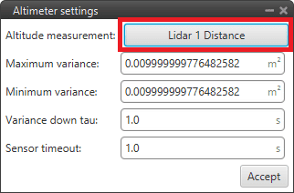
Altimer sensor configuration - Block Programs
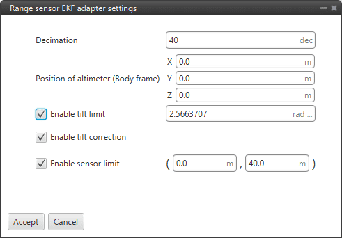
Altitude EKF adapter configuration - Block Programs
For more information on these blocks, see Altimeter sensor and Altitude EKF adapter of Block Programs section.
Automation: This automation will trigger a change of phase, Flare phase, when the aircraft is landing and at 5 m AGL.
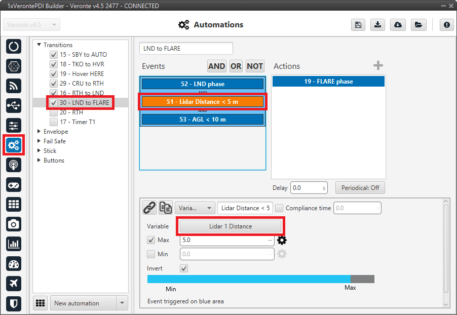
Lidar automation example
For more information on automations, see Automations section.
Radar
Radar altimeters are common devices on aircrafts.
Ainstein CAN Radar
The following explanation corresponds to the integration of the Ainstein CAN Radar.
These settings will allow Autopilot 1x to read out via CAN A the radar altimeter reading, in particular distance.
Note
In the datasheet of the radar, the user can access the complete protocol of the device.
Go to Input/Output menu \(\rightarrow\) CAN Setup section \(\rightarrow\) Configuration tab.
Connect an Input Filter to Custom message 1, in this example Input Filter 2. and configure to read from CAN A:
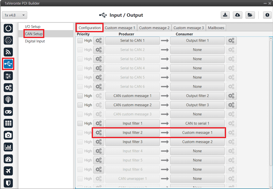
CAN Setup - Input Filter
Configure this Input Filter to read from CAN A, with Id 589826 and allow both types of messages to enter the input filter (since the radar altimeter uses extended IDs).
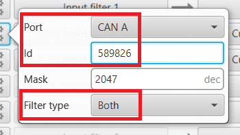
CAN Setup - Input Filter configuration
After specifying that Custom message 1 will receive the data from CAN A, go to Mailboxes tab.
Configure a CAN A mailbox for extended CAN ID message: 589826:

Mailboxes configuration
Go to UI menu \(\rightarrow\) Variables section \(\rightarrow\) Reals Vars tab.
Rename a User Variable that will be used to store the measurement read from the radar:
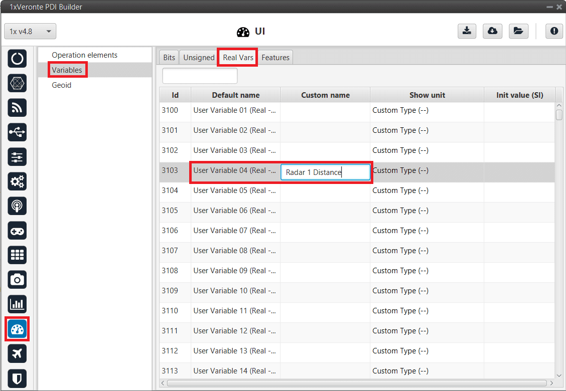
User Variable renamed
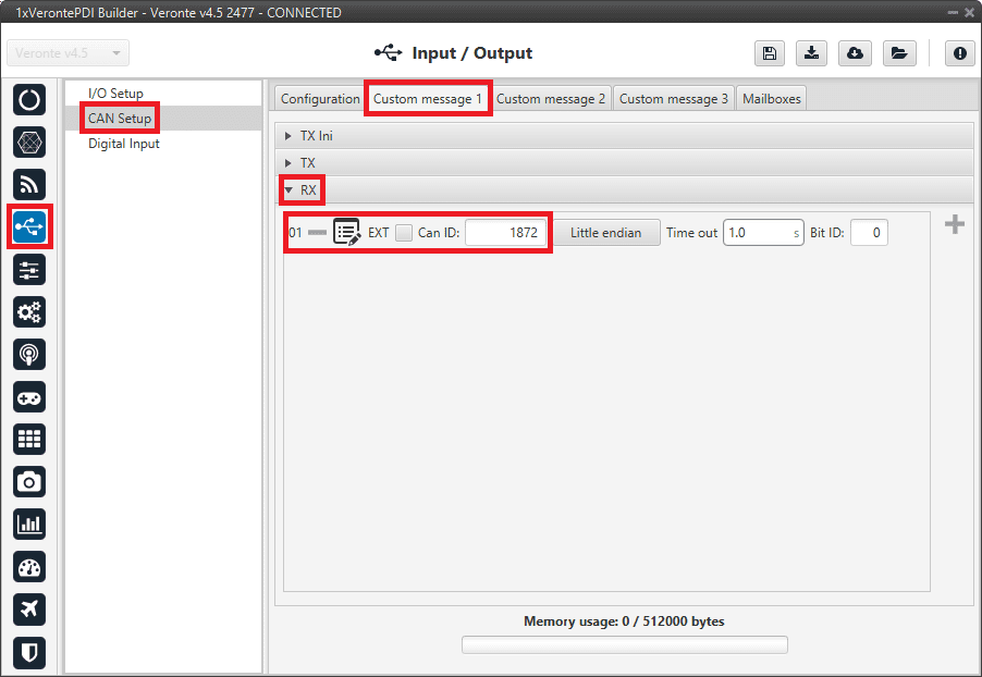
Finally, go to Input/Output menu \(\rightarrow\) CAN Setup section \(\rightarrow\) Custom message 1 tab.
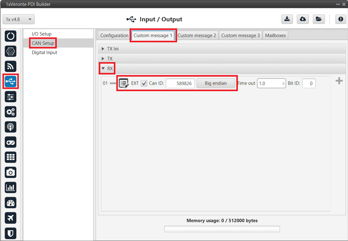
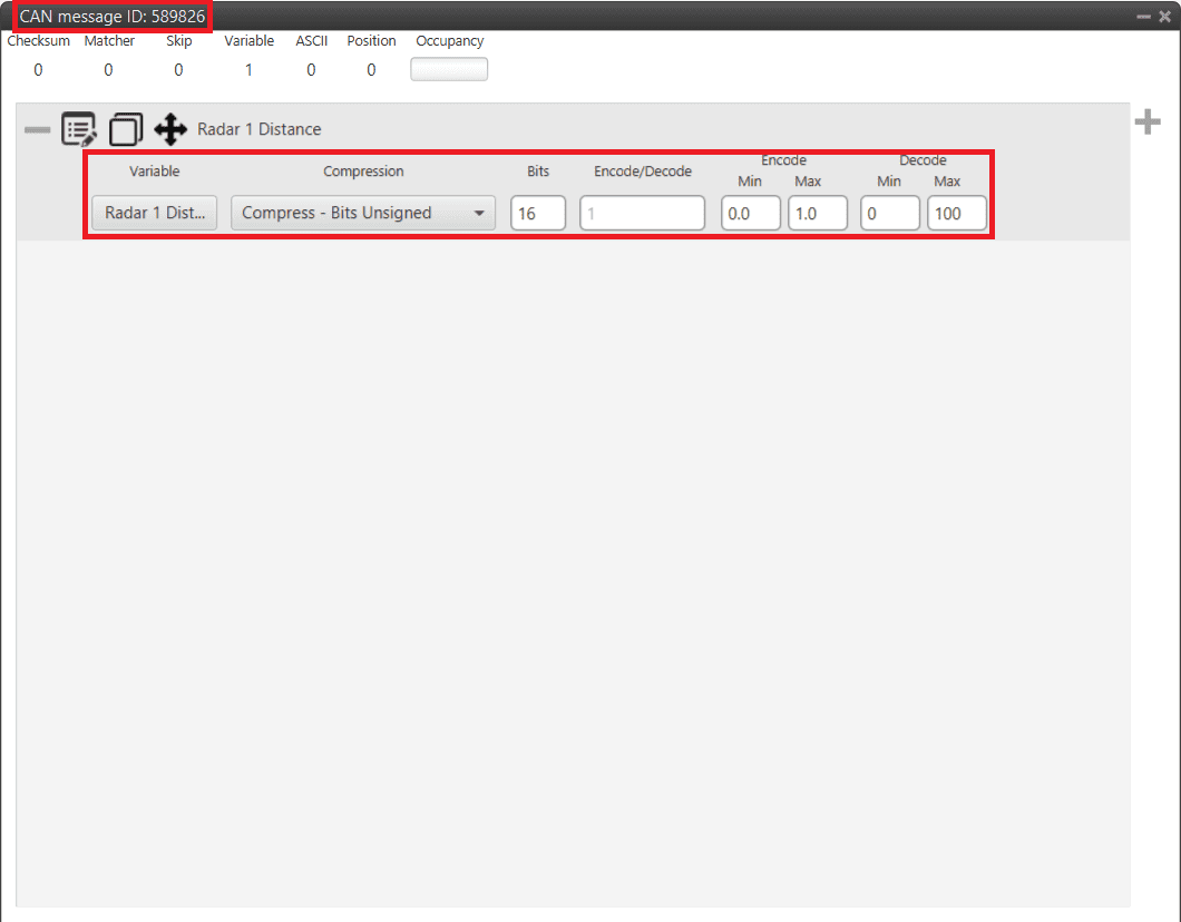
For more details on CAN configuration see CAN Setup section.
Smartmicro CAN Radar
The following explanation corresponds to the integration of the Smartmicro CAN Radar. For more information on the Smartmicro Radar - Altimeter datasheet, the user can go to:
These settings will allow Autopilot 1x to read out via CAN A the radar altimeter readings, in particular AGL and vertical speed.
Note
In the datasheet the user can access the complete protocol of the device.
Go to Input/Output menu \(\rightarrow\) CAN Setup section \(\rightarrow\) Configuration tab.
Set an Input Filter to read from CAN A in Custom message 1, in this example Input Filter 3.
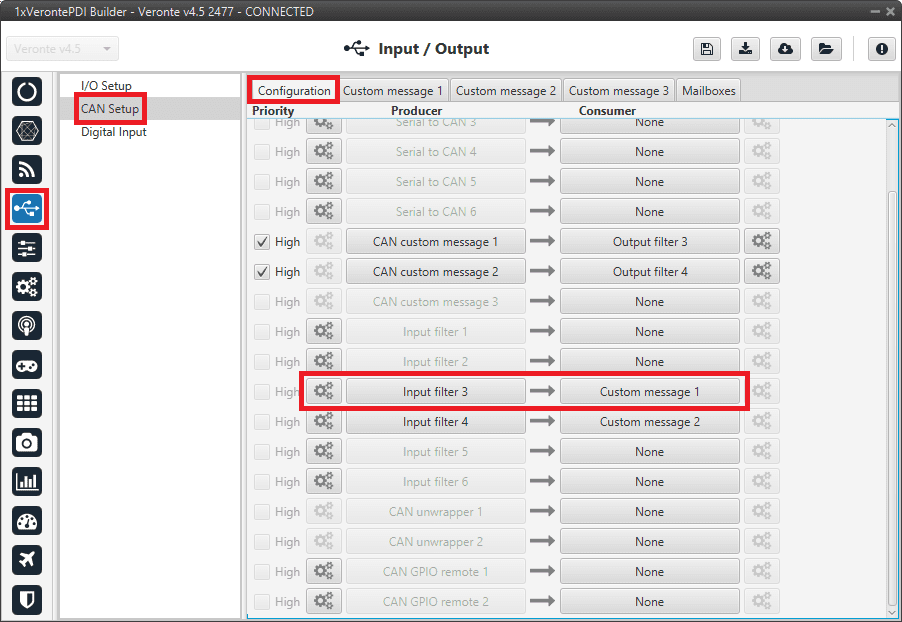
CAN Setup - Input Filter
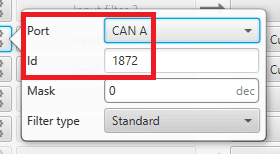
CAN Setup - Input Filter configuration
After specifying that Custom message 1 will receive the data from CAN A, go to Mailboxes tab.
Configure the CAN A baudrate:
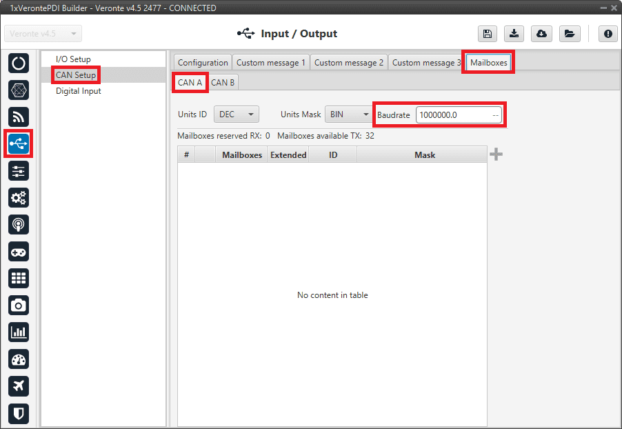
Baudrate configuration
Once the baudrate is set, configure CAN A mailboxes for CAN ID message: 1872.
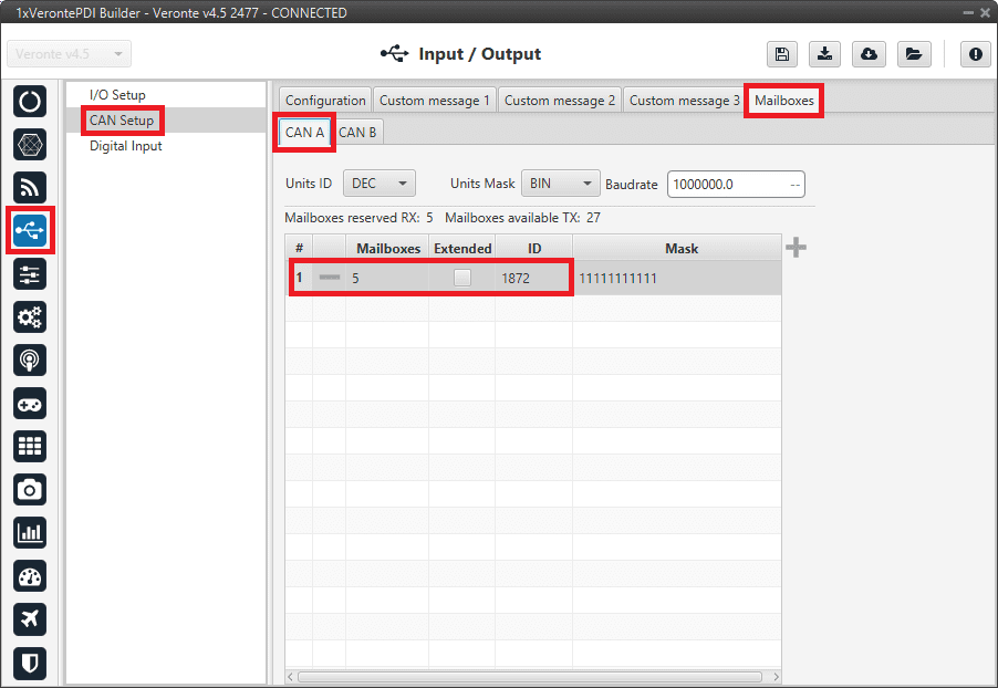
Mailboxes configuration
Go to Custom message 1 tab.
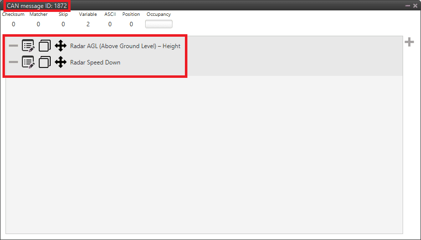
For more details on CAN configuration see CAN Setup section.
Note
CAN ID messages and messages content will change for different Radar altimeters. Check the documentation of your device for further details.