Navigation blocks
EKF Adapters
These blocks allow the connection between the autopilot sensors (internal or external) and the calculation of the navigation algorithm. That is, they “convert” the sensor data into EKF data in order to implement them in the navigation block (Extended Kalman Filter algorithm).
For this reason, EKF Adapters blocks normally work with the Sensor blocks as inputs.
Altitude
Altitude block adapts an exteral altimeter sensor, like LIDAR, Sonar, etc., to the EKF input.

Altitude block
Inputs
 Alt: Altitude measurement as a 3-dimensional real array with the following components: 0-Update flag, 1-Altitude measurement, 2-Variance. This input corresponds to the Altitude Sensor block.
 (Optional) enable: Optional boolean input to enable (true) or disable (false) the input in the EKF. Not connected means enabled.
Output
 Pin 0: EKF input data (H, R, y).
Note
H: Observation matrix.
R: Measurement covariance matrix.
y: Measurement.
Configuration menu:
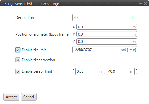
Altitude block configuration
The following acceletometer parameters must be configured:
Decimation: Parameter that defines the group of measurements for which 1 value will be stored. For example, if the decimation is 10, every 10 measurements will be counted as 1. This procedure is used to reduce the number of samples. Recommended value 40 (in decimal units).
Position of altimeter (Body frame): Parameter to indicate the distance from the altimeter to the centre of gravity of the platform. This is used to take into account the weight of the altimeter in the aircraft control.
Enable tilt limit: The altimeter is normally installed in a fixed position having a constant direction with respect to the platform. Taking a LIDAR as an example, it is used to measure altitude so it has to point towards the ground, in a direction parallel to the Z body axis. When the vehicle is not level on its X or Y axis (has a pitch or roll angle different from zero), the LIDAR will not point in a direction perpendicular to the ground, and the measurement taken will not be the real altitude of the aircraft. This option is a safe condition to discard the measure of an altimeter when its tilt angle exceeds a certain value defined here.
Enable tilt correction: Allows the correction of the altimeter sensor measurement, normally AGL measurent, with internal pitch and roll measurements.
\[correction = (AGL \; measurement) · \cos (pitch) · \cos (roll)\]Enable sensor limits: It is the range in which the sensor measurement is taken to be processed by 1x PDI Builder. Any external value will be discarded by the system.
The following figure shows a diagram with the values of maximum and minimum sensor limits altitude, and the maximum tilt angle.

Altitude block - Limits
GNSS compass
GNSS compass block takes two relative position measurements and converts them to misalignment vectors to use in the EKF for attitude correction.

GNSS compass block
Inputs: These inputs correspond to the GNSS Sensor block.
 Drn1: Relative position measurement 0 as a 10-dimensional real array with the following components:
0: Update flag
1: Rover flag: 1 is rover, 0 is base
2: Time stamp
3: North relative distance
4: East relative distance
5: Down relative distance
6: Relative distance variance
7: X body antenna position
8: Y body antenna position
9: Z body antenna position
 Drn2: Relative position measurement 1 as a 10-dimensional real array with the same components as described above.
Outputs
 NED: Baseline vector in NED frame as a 5-dimensional real array with the following components:
0: Update flag (always 1)
1: North component
2: East component
3: Down component
4: Variance
 Body: Baseline vector in body frame as a 5-dimensional real array with the following components:
0: Update flag (always 1)
1: X body component
2: Y body component
3: Z body component
4: Variance.
An example of how to implement this block is presented below:
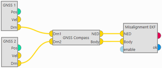
GNSS compass block example
Misalignment
Misalignment block transforms from two vectors expressed in NED and body frames to EKF misalignment data for attitude correction.
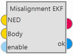
Misalignment block
Inputs
 NED: Vector measured in NED frame as a 5-dimensional real array with the following components:
0: Update flag (always 1)
1: North component
2: East component
3: Down component
4: Variance
 Body: Vector measured in body frame as a 5-dimensional real array with the following components:
0: Update flag (always 1)
1: X body component
2: Y body component
3: Z body component
4: Variance.
 (Optional) enable: Optional boolean input to enable (true) or disable (false) the input in the EKF. Not connected means enabled.
Outputs
 Pin 0: EKF input data (H, R, y).
Note
H: Observation matrix.
R: Measurement covariance matrix.
y: Measurement.
 ok: Measurement check bit, returns true if the measurements pass the module checks, false otherwise.
Configuration menu:

Misalignment block configuration
The following parameters are configurable:
Norm diff. threshold: In order to use the measures that enter the block, the moduli of both measurements must be similar according to the equation:
\[|\frac{nmn - nmbn}{(nmn + nmbn) \cdot ndthr}| < 1\]Where,
\(nmn\): This is the norm of the first input vector.
\(nmbn\): This is the norm of the second input vector.
\(ndthr\): Norm diff. threshold as a percentage of one, users should look at the absolute value.
Minimum norm: In addition, it must also be fulfilled that the moduli of the measures are greater than the Minimum norm defined here.
Norm filter: This parameter is to filter the measurement of \(|\frac{nmn - nmbn}{(nmn + nmbn) \cdot ndthr}|\) to use it in the Madgwich algorithm.
Decimation: Parameter that defines the group of measurements for which 1 value will be stored. For example, if the decimation is 10, every 10 measurements will be counted as 1. This procedure is used to reduce the number of samples. Recommended value 10 (in decimal units).
Use 3D: If enabled, the attitude correction will be in 3D, as by default, only the attitude correction in the horizontal plane is activated.
Position
Position block adapts absolute position data to EKF data for position update.
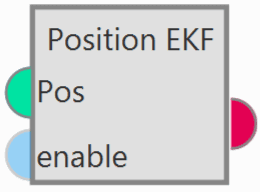
Position block
Inputs
 Pos: Absolute position measurement. This input corresponds to the GNSS Sensor block or Relative position sensor block.
 (Optional) enable: Optional boolean input to enable (true) or disable (false) the input in the EKF. Not connected means enabled.
Outputs
 Pin 0: EKF input data (H, R, y).
Note
H: Observation matrix.
R: Measurement covariance matrix.
y: Measurement.
Configuration menu:
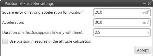
Position block configuration
Users must configure the following parameters:
Square error on strong acceleration for position: Under strong acceleration the variance for the position solution is changed to the specified value.
Acceleration: Threshold definition. When this threshold is exceeded, strong acceleration variances are considered.
Duration of effect (disappears linearly with time): Time needed to restore the default variances of the GNSS solution.
Use position measures in the attitude calculation: When enabled, the position data from the GNSS solution is considered for the attitude estimation.
Static Pressure
Static Pressure block converts static pressure measurement into EKF data for altitude update.
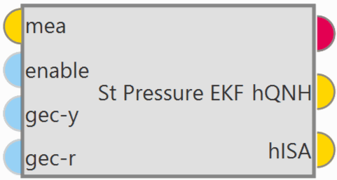
Static Pressure block
Inputs
 mea: Static pressure measurement as a 3-dimensional real array with the following components:
0: Update flag
1: Pressure
2: Variance
This input corresponds to the Static Pressure sensor block.
 (Optional) enable: Optional boolean input to enable (true) or disable (false) the input in the EKF. Not connected means enabled.
 (Optional) gec-y: Enable ground effect measurement correction (true) or disable (false). Not connected means disabled.
 (Optional) gec-r: Enable ground effect variance increment (true) or disable (false). Not connected means disabled.
Outputs
 Pin 0: EKF input data (H, R, y).
Note
H: Observation matrix.
R: Measurement covariance matrix.
y: Measurement.
Configuration menu:
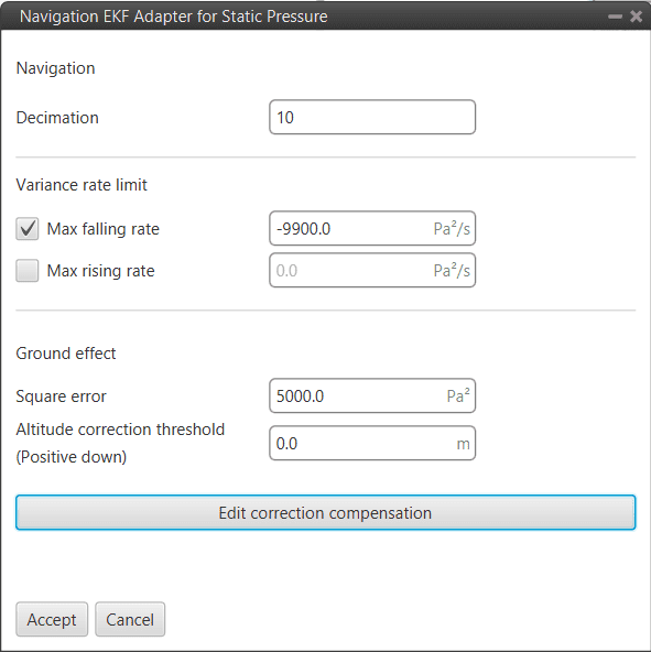
Static Pressure block configuration
The following parameters must be configured:
Navigation
Decimation: Parameter that defines the group of measurements for which 1 value will be stored. For example, if the decimation is 10, every 10 measurements will be counted as 1. This procedure is used to reduce the number of samples. Recommended value 10 (in decimal units).
Variance rate limit
Max falling rate: Defines the maximum falling rate of the system.
Max rising rate: Defines the maximum rising rate of the system.
Ground effect: Veronte Autopilot 1x is configured to apply a correction to the Ground Effect for landing purposes, which needs to be configured here.
Square error: This value is automatically calculated from the square error of the static pressure sensor (see Static Pressure sensor block).
Altitude correction threshold (Positive down): The user has to define an Altitude Difference for the system to apply the Grouund Effect. While landing, the aircraft will feel a decrease in the static pressure due to the Ground Effect, and this pressure difference (transformed into meters) is the Threshold that can be configured here. If set to 0, whenever Ground Effect is enabled, it will make its effect.
In other words, Altitude error is the measurement from the static pressure sensor in meters minus the estimated state of the UAV.
Explanation
The ground effect creates a high pressure below the UAV when it is close to the ground, this increase in pressure readings produces the navigation to “go down”. Veronte Autopilote 1x can mitigate the ground effect in two ways:
1: Increasing the static pressure sensor variance (R) used for the Extended Kalman filter. This means that other height sources, for example GNSS will be used more strongly to estimate the altitude near the ground. This is configured with the boxes “Square error” and “Altitude correction threshold (Positive down)”. If enabled, the R used in the EKF for the static pressure sensor will be increased to be the value configured in the box when the “altitude error” measured by the static pressure sensor is higher than the configured threshold in the down direction. Example, if the current estimated state of the UAV is 10 meters MSL and the measurements from the static pressure sensor tell that the UAV is at 5 meters MSL. If the “Altitude correction threshold (Positive down)” is less than 5 then the R used for this sensor will be the one configured in the “Square error”. Please notice that ground effect correction must only be enabled when close to the ground so that the navigation performance is not negatively impacted when there is no ground effect.
2: Modifying the actual measurement of the static pressure sensor. When this function is enabled the “altitude error” corresponding to the static pressure sensor is modified according to the table. The idea is that altitude errors that would make the estimation of the height to go down are changed to reduce the altitude error. It is also important to only enable this when close to the ground. Using the same example as before, the 5 meters down of altitude error for this sensor would be transformed to only 4 meters for example, that way this sensor would pull down the estimated altitude a little bit less.
Note
Please note that these two ways of compensating the ground effect can be enabled/disabled separately and that they only have to be used when close to the ground. It is recommended to test in controlled conditions.
Correction compensation: Users can edit the correction compensation by clicking here:

Static Pressure block configuration - Correction compensation table
The user can add or remove points from the correction compensation table. The correction will have the ‘shape’ made by these points. The altitude error used is computed from the actual altitude error by interpolating in the table (with extrapolation).
X-axis: Actual altitude error
Y-axis: Actual error used in EKF
Note
The unit of measurement is meters.
Terrain height
Terrain height block transforms from terrain height measurement to EKF data for terrain height update.

Terrain height block
Inputs
 height: Terrain altitude as a 4-dimensional real array with the following components:
0: Update flag (always 1)
1: Valid flag (inside mesh)
2: Terrain height
3: Variance
This input corresponds to the SRTM height sensor block.
 (Optional) enable: Optional boolean input to enable (true) or disable (false) the input in the EKF. Not connected means enabled.
Output
 Pin 0: EKF input data (H, R, y).
Note
H: Observation matrix.
R: Measurement covariance matrix.
y: Measurement.
Configuration menu: The user must configure the decimation of this sensor.

Terrain height block configuration
This parameter defines the group of measurements for which 1 value will be stored. For example, if the decimation is 10, every 10 measurements will be counted as 1. This procedure is used to reduce the number of samples. Recommended value 2 (in decimal units).
Velocity
Velocity block converts velocity measurement into EKF data for velocity update.
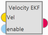
Velocity block
Inputs
 Vel: Velocity measurement as a 12-dimensional real array with the following components:
0: Update flag
1: Fix flag
2: North velocity
3: East velocity
4: Down velocity
5: North velocity variance
6: East velocity variance
7: Down velocity variance
8: X body antenna position
9: Y body antenna position
10: Z body antenna position
11: Measurement delay
This input corresponds to the GNSS Sensor block.
 (Optional) enable: Optional boolean input to enable (true) or disable (false) the input in the EKF. Not connected means enabled.
Output
 Pin 0: EKF input data (H, R, y).
Note
H: Observation matrix.
R: Measurement covariance matrix.
y: Measurement.
Configuration menu:
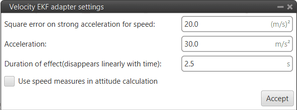
Velocity block configuration
Users must configure the following parameters:
Square error on strong acceleration for speed: Under strong acceleration the variance for the speed solution is changed to the specified value.
Acceleration: Threshold definition. When this threshold is exceeded, strong acceleration variances are considered.
Duration of effect (disappears linearly with time): Time required to restore the default variances of the GNSS solution.
Use speed measures in the attitude calculation: When enabled, the speed data from the GNSS solution is considered for the attitude estimation.
Velocity down
Velocity down block adapts the velocity down measurement to EKF data for velocity down update.
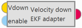
Velocity down block
Inputs
 Vdown: Velocity measurement down measurement.
 (Optional) enable: Optional boolean input to enable (true) or disable (false) the input in the EKF. Not connected means enabled.
Output
 Pin 0: EKF input data (H, R, y).
Note
H: Observation matrix.
R: Measurement covariance matrix.
y: Measurement.
Configuration menu:
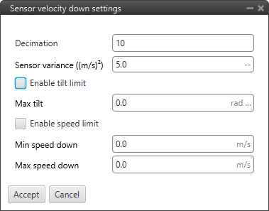
Velocity down block configuration
The following parameters must be configure:
Decimation: Parameter that defines the group of measurements for which 1 value will be stored. For example, if the decimation is 10, every 10 measurements will be counted as 1. This procedure is used to reduce the number of samples. Recommended value 10 (in decimal units).
Sensor variance ((m/s)²): Sensor error variance in metres per second squared.
Enable tilt limit: The sensor measures the variable in a direction perpendicular to the longitudinal axis of the platform, so when it is tilted the reading will not be reliable. This option allows the definition of a tilt limit, so that if the limit is reached, the sensor reading will be discarded.
Max tilt: A maximum tilt can be defined.
Enable speed limit: This option allows a speed limit to be set, so that if the limit is reached, the sensor reading will be discarded.
Min speed down: Defines the minimum limit of the speed measured by the sensor.
Max speed down: Defines the maximum limit of the speed measured by the sensor.
EKF Split
EKF Split block shows all the sensor information that is going into the EKF algorithm.
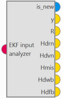
EKF Split block
Input
 Pin 0: EKF input data from any EKF input adapter block (H, R, y).
Outputs
 is_new: Update flag (true when a new measurement is generated, false otherwise).
 y: Measurement. (3-dimensional real array)
 R: Measurement covariance matrix. (3-dimensional real array)
 Hdrn: Observation matrix for the position increment states. (9-dimensional real array)
 Hdvn: Observation matrix for the velocity increment states. (9-dimensional real array)
 Hmis: Observation matrix for the misalignment states. (9-dimensional real array)
 Hdwb: Observation matrix for the gyroscope bias increment states. (9-dimensional real array)
 Hdfb: Observation matrix for the terrain altitude increment state. (9-dimensional real array)
This block is designed for any EKF adapter block, i.e. a standard block for all EKF adapter blocks, therefore some outputs only correspond to a certain type of EKF adapter block. And, consequently, the outputs that do not correspond to the connected block, will get 0 as value.
Attention
Be careful! Check that the blocks to which the outputs are connected match in size with the data, i.e. if the output is a 9-dimensional real array, a split block or a multiple user real variable with size 9 va must be connected to it in order to display the data.
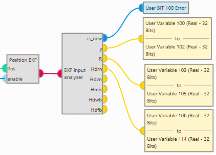
EKF Split block - Example
Navigation
Navigation block updates the Veronte navigation variables (position, velocity, attitude, etc.) based on the current selected navigation source.
Note
This block has by default 1 input, in its configuration the user must set the desired size of inputs.
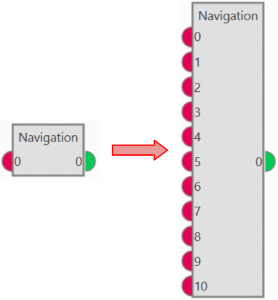
Navigation block
Veronte Autopilot 1x integrates a navigation system that can operate with GPS and without GPS coverage.
In the navigation with GPS, the system uses it to fly the aircraft along a route or to a given waypoint. It is possible to control the aircraft’s position (longitude and latitude) and the altitude. This is the navigation used by default by the system when everything is working properly.
In case the GPS signal is lost, the navigation can easily measures the attitude angles with a greater precision than using a simple IMU. With these measures, it is possible for the system to control pitch, roll and yaw and then maintain a safe attitude when the GPS signal is lost, avoiding any possible malfunctions. It is recommended to create an automation to change to a phase where the attitude angles are controlled, in case of loss of GPS signal. For more information visit Automations.
Note
The yaw can be measured in the navigation without GPS only if the magnetometer is activated in the navigation window.
Input
Output
 0: Index + 1 of the current input measurement used to update the EKF state. A value of zero means that no measurements have been input to the EKF in the current step.
Configuration menu: This menu contains the parameters used in the Kalman Filter algorithm to fuse the information provided by the different sensors. This data is used in the navigation system to generate the commands sent to the aircraft.

Navigation block configuration
Warning
The values that appear here should only be changed by advanced users. If the user is not familiar with the Kalman Filter algorithm and Sensor Fusion, do not change the default parameters.
If further information is required, please contact the support team (create a ticket in the customer’s Joint Collaboration Framework; for more information, see Tickets section of the JCF manual).
Although this configuration menu must be set by default or modified by advanced users, the 2 following parameters must be configured by all users:
Inputs size: Users must set the number of inputs.
Navigation: The type of navigation must be selected, tha available options are:
Internal: Uses internal data for navigation. Data (position, attitude, etc.) is processed into 1x unit from sensor measures.
External VCP: Uses external data for navigation. Data (position, attitude, etc.) is provided by Veronte Communication Protocol (VCP).
External Var: Uses external data for navigation.
It takes directly the attitude, velocity and acceleration data of the following real variables from the memory:
ID 259: External yaw
ID 260: External pitch
ID 261: External roll
ID 262: External roll rate
ID 263: External pitch rate
ID 264: External yaw rate
ID 265: External veloctiy north
ID 266: External velocity east
ID 267: External velocity down
ID 268: External acceleration x body axis
ID 269: External acceleration y body axis
ID 270: External acceleration z body axis
ID 271: External GPS Time of Week
Position data is read from the Moving Feature 00.
Vectornav VN-300: Uses external data for navigation. Data (position, attitude, etc.) is provided by Vectornav VN-300. For more information, see the Vectornav VN-300 -> Integration examples section of this manual.
Wind
By clicking on the ‘Wind Estimation’ button, a configuration menu will be displayed:
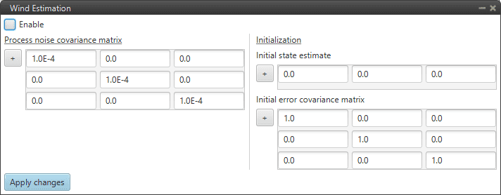
Wind Estimation configuration
To make a proper estimate, the system needs to collect as much wind information as possible, so missions with a trajectory involving changes in directions will result in a better wind estimate compared to a straight trajectory mission.
The computed result is displayed in the variables: Wind Velocity Down, Wind Velocity East, Wind Velocity North.
Warning
The values that appear here should only be changed by advanced users.
