Sensors blocks
Sensors blocks allows to configure any sensor connected externally or internally to Veronte Autopilot 1x.
As the outputs of these blocks are not ‘ready’ to be directly implemented in the navigation block (EKF algorithm), these blocks are usually connected afterwards to EKF Adapters blocks.
Altimeter
Altimer sensor block configures the parameters of external altimeters.
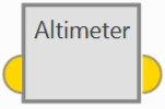
Altimeter block
Input
 Pin 0: Sensor variance.
Output
Pin 0: Measurement as a 3-dimensional real array with the following components:0: Update flag
1: Altitude measurement
2: Variance
Configuration menu:
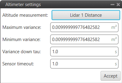
Altimeter block configuration
The following parameters must be configured:
Altitude measurement: A real variable must be selected from which the altitude measurement is read. The parameters defined here shall be applied to this input variable.
Maximum variance: Maximum variance applied to the measurement after measurement lost.
Minimum variance: Minimum variance applied to the measurement after recovering from a measurement lost.
Variance down tau: Filter constant. Smoothing parameter for the transition from maximum to minimum variance.
Sensor timeout: Time before considering measurement lost.
Note
If the measurement does not change during this time, the autopilot may consider that no measurement is entered, and therefore, the timeout is fulfilled.
GNSS sensor
GNSS sensor block configures GNSS receivers, RTK and External source.
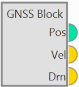
GNSS sensor block
Outputs
 Pos: Absolute position measurement. Vel: Velocity measurement as a 12-dimensional real array with the following components:
0: Update flag
1: Fix flag
2: North velocity
3: East velocity
4: Down velocity
5: North velocity variance
6: East velocity variance
7: Down velocity variance
8: X body antenna position
9: Y body antenna position
10: Z body antenna position
11: Measurement delay
Drn: Relative position measurement as a 10-dimensional real array with the following components:0: Update flag
1: Rover flag (one is rover, zero is base)
2: Time stamp
3: North relative distance
4: East relative distance
5: Down relative distance
6: Relative distance variance
7: X body antenna position
8: Y body antenna position
9: Z body antenna position
Configuration menu:
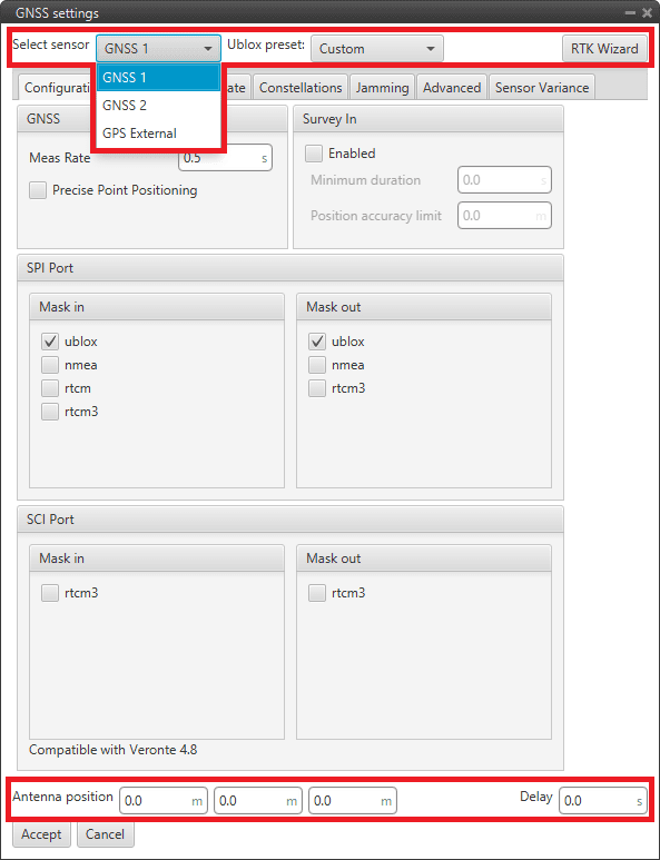
GNSS sensor block configuration
The parameters to be configured in the first and last row of this configuration menu are presented below:
Select sensor: The first parameter to select is the GNSS sensor: GNSS 1, GNSS 2 or GPS External. Depending on the sensor selected, the block will change name and configuration menu.
However, GNSS 1-2 have the same configuration menu.
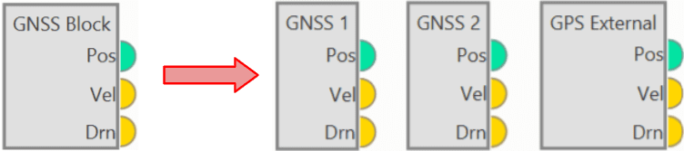
GNSS sensor blocks
Ublox preset: By default, Custom is selected. If an option other than Custom is selected, users will only be able to configure the ‘Sensor Variance’ tab (this tab will be described below).
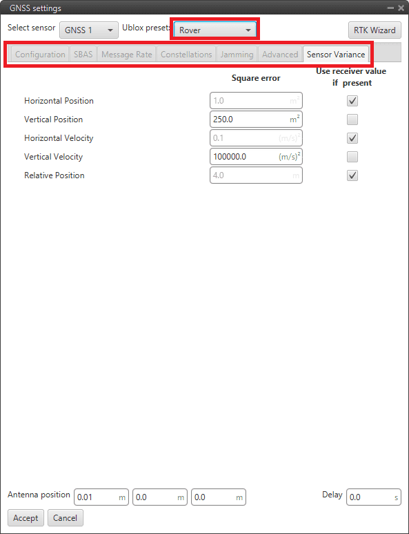
GNSS sensor block configuration - Rover/Dynamic base/Static base
Custom: This option allows the user to modify all the tabs that appear in this menu (all tabs are described below).
Rover: By choosing this option, a default ‘Rover’ configuration will be selected for this block. This corresponds to AIR units of the RTK wizard (described below).
Dynamic base: By choosing this option, a default ‘Dynamic base’ configuration will be selected for this block. This corresponds to GNSS Compass of the RTK wizard (described below).
Static base: By choosing this option, a default ‘Static base’ configuration will be selected for this block. This corresponds to GND units of the RTK wizard (described below).
For more information on these default configurations, click here (go to section 3.1.5).
RTK Wizard: This interface helps the user configuring everything related to RTK or GNSS Compass. By clicking here, the configuration menu will be displayed:
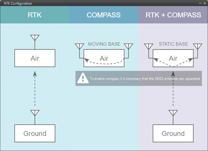
GNSS sensor block configuration - RTK Wizard
In this menu, the user can find 3 different options:
RTK: Stands for Real Time Kinematics (RTK) and it is a satellite navigation technique used to enhance the precision of position data derived from satellite-based positioning systems.
To work, it requires 2 GNSS receivers placed in different autopilots.
By clicking on ‘Air’, a default ‘Rover’ configuration will be loaded in this block. Likewise, by clicking on ‘Ground’, a default ‘Static base’ configuration will be selected.
Compass: The GNSS compass provides accurate dual antenna GNSS-based heading that is not subject to magnetic interference.
It requires 2 GNSS receivers placed on the same autopilot to work. By clicking on ‘Air’, a default ‘Dynamic base’ configuration will be loaded.
RTK + Compass: Hybrid combination where both tools are employed at the same time in a system where the AIR unit must have 2 GNSS receivers and the GND must have, at least, 1 GNSS reseiver.
By clicking on ‘Air’, a default ‘Rover’ configuration will be loaded in this block. Likewise, by clicking on ‘Ground’, a default ‘Static base’ configuration will be selected.
Antenna position: It is used to set the relative distance to the center of mass from the GNSS antenna in aircraft body axis. This parameter has to be set correctly in order to get a correct value when using GNSS Compass.
Delay: Delay with which the GPS information is ‘picked up’, as the GPS may have a small delay while it reads and processes the information. In case the user has selected GNSS 1 or GNSS 2, the internal GPS of the Veronte Autopilot 1x has a default delay of 0.5 seconds.
GNSS 1-2 configuration menu:
Configuration: This menu contains some of the parameters needed to configure the GNSS 1-2 receiver located in Veronte Autopilot 1x.
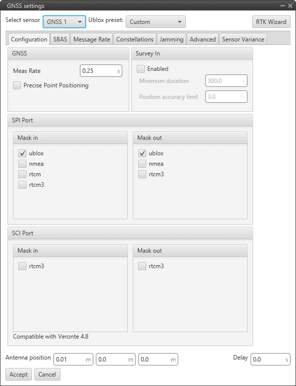
GNSS 1/2 sensor block configuration - Configuration tab
The following parameters are configurable:
GNSS: Data values that can be configured.
Meas Rate: Defines the minimum time between data acquisition.
Precise Point Positioning (PPP): This option is a precise global positioning service. PPP is able to provide centimetre to decimetre level positioning solutions after a few minutes with an unobstructed view of the sky.
Survey In: Determines the position of a stationary receiver by building a weighted average of all valid 3D position solutions.
This mode should be activated on a Ground unit to enable GNSS Differential mode and send corrections to the Air unit. Two requirements must be specified to stop the procedure. Survey in procedure shall end when both requirements are met:
Minimum duration: Defines a minimum amount of observation time independent of the actual number of valid fixes that were used for the position calculation.
Reasonable values range from one day for high accuracy requirements to a few minutes for approximate position determination.
Position accuracy limit: Defines a limit on the dispersion of positions contributing to the calculated mean.
SPI Port: Allows the user to select the different comunication protocols as input or output. One port can handle several protocols at the same time (e.g. NMEA and UBX).
Mask in: Defines the inputs, i.e., receives the data (usually the air unit). The available protocols are UBX, NMEA, RTCM and RTCM3.
Mask out: Defines the outputs, i.e. sends the data (usually the ground unit). The available protocols are UBX, NMEA and RTCM3.
More information on protocols and configuration can be found in the U-blox documentation.
SCI Port: In this case, RTK messages that are sent through the RTCM3 protocol are connected directly through an SCI port, so they do not occupy the bandwidth of the SPI port.
Note
Only for Veronte version 4.8 and higher.
SBAS: SBAS stands for Satellite Based Augmentation System. It is a set of geostationary satellites that are used to check the status of the signals sent by GPS Satellites and to improve tracking by correctiong for atmospheric disturbations, orbit deviations, clock errors, etc.
In 1x PDI Builder, it is possible to select the satellites to be used for this purpose by selecting the numbers listed in the table in the figure below or have the software choose them automatically according to the location of the platform.
The automatic option is recommended.
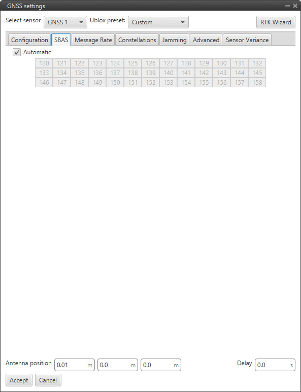
GNSS 1/2 sensor block configuration - SBAS tab
Message Rate: The Message rate options are used to set the time between the messages received on the autopilot. Each of the different messages can be configured separately: ECEF (Earth Centred Fixed Reference Frame), LLH (Latitude, Longitude and Height), Speed, GPS Time, SV Status (status of the GPS satellite), etc.

GNSS 1/2 sensor block configuration - Message Rate tab
More information on the list of RTCM 3 messages can be found here.
Constellations: In this tab, the user can select which GNSS constellations are being used from the supported constellations listed in the figure below:

GNSS 1/2 sensor block configuration - Constellations tab
SBAS
Galileo
BeiDou
QZSS
GLONASS
Jamming: This menu allows the user to configure an indicator for both broadband and continuous wave (CW) jammers/interference. The receiver monitors the background noise and looks for significant changes.
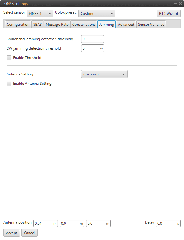
GNSS 1/2 sensor block configuration - Jamming tab
Enable Threshold: Enables the interference detection. Therefore, if broadcast or CW jamming is reported, Veronte Autipilot will disregard the GPS information, position not fixed.
Broadband jamming detection threshold: If the value rises significantly above this threshold, this indicates that a broadband jammer is present.
CW jamming detection threshold: If the value rises significantly above this threshold, this indicates that a continuous wave (CW) jammer is present.
Enable Antenna Setting.
Antenna Setting: It is also possible to specify whether the receiver expects an active or a passive antenna; unknown option if the user does not know the behaviour of the antenna.
Advanced: The values shown here should only be modified by advanced users. For this reason, the following message appears when entering this tab:

GNSS 1/2 sensor block configuration - Warning advanced tab
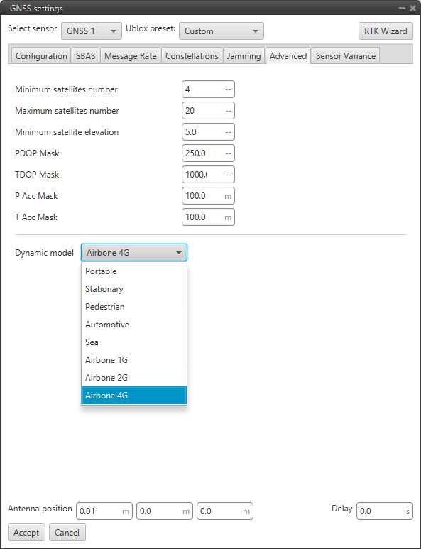
GNSS 1/2 sensor block configuration - Advanced tab
Warning
Modifying these parameters can cause problems during the acquisition of GNSS positioning.
Minimum satellites number: Minimum number of satellites needed to have position fixed.
Maximum satellites number: Maximum number of satellites needed to have position fixed
Minimum satellite elevation: Minimum elevation of a satellite to be considered. Value in degrees.
PDOP mask: Maximum Position Dilution of Precision to consider the solution.
TDOP mask: Maximum Time Dilution of Precision to consider the solution.
P Acc mask: Maximum Position Accuracy to consider the solution.
T Acc mask: Maximum Time Accuracy to consider the solution.
Dynamic model
The embedded receiver supports different dynamic platform models to adjust the GNSS navigation engine to the expected application environment. The settings improve the receiver’s interpretation of the measurements and thus provide a more accurate position output. Setting the receiver to an unsuitable platform model for the given application environment is likely to result in a loss of receiver performance and position accuracy.
Platform
Description
Portable
Applications with low acceleration.
Stationary
Stationary applications. Velocity restricted to 0 m/s. Zero dynamics assumed
Pedestrian
Applications with low acceleration and speed. Low acceleration assumed.
Automotive
Used for applications with equivalent dynamics to those of a car. Low vertical acceleration assumed.
Sea
Recommended for applications at sea, with zero vertical velocity. Zero vertical velocity assumed. Sea level assumed.
Airborne 1G
Used for applications with a higher dynamic range and greater vertical acceleration than a car.
Airborne 2G
Recommended for typical airborne environments.
Airborne 4G
Recommended for extremely dynamic environments.
Sensor Variance: The variances considered in the EKF for the GNSS solution are by default the values provided by the GNSS receiver but can be modified for more complex scenarios.

GNSS sensor block configuration - Sensor variance tab
Horizontal Position: Variance for the North and East components of the position solution.
Vertical Position: Variance for the Down component of the position solution.
Horizontal Velocity: Variance for the North and East components of the velocity solution.
Vertical Velocity: Variance for the Down component of the velocity solution.
Relative Position: This is the variance of the relative position from one GNSS receiver to another.
GPS External configuration menu: If the GNSS information is received via an external system, the user must configure it in this menu, so that this system can be included in the navigation filters.
After correctly configuring the communication protocol in the corresponding channel (RS 232, RS485, CAN, …) the GPS External variables of interest must be filled in this interface:
Configuration:
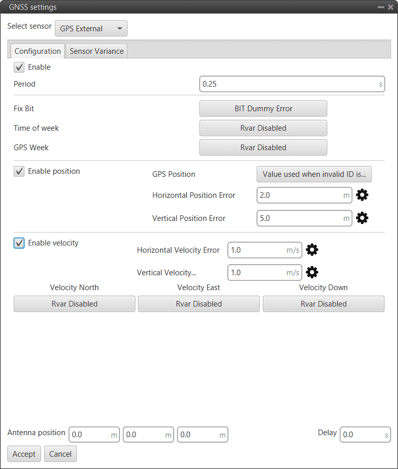
GPS External sensor block configuration - Configuration tab
Caution
Check GNSS External device communication protocol before filling this menu.
The user must create a Custom Message according to the communication protocol used by the external sensor, so that its readings are stored in system variables. Then, the user can select these variables to configure the following parameters:
Enable.
Period: Defines the period of incoming information from the external system.
Fix Bit: Data provided by the external device which is important to know the status of the positioning.
Time of week: Variable extracted from the communication protocol defining the time of the week.
GPS Week: Variable extracted from the communication protocol defining the week.
Enable position:
GPS Position: Variable defining latitude, longitude and height from GNSS. Usually Moving Object variables are used in 1x PDI Builder.
Horizontal Position Error: Defined by the GNSS External device provider.
Vertical Position Error: Defined by the GNSS External device provider.
Enable Velocity:
Horizontal Velocity Error: Defined by the GNSS External device provider.
Vertical Velocity Error: Defined by the GNSS External device provider.
Velocity North/East/Down: Variables extracted from the communication protocol defining GNSS velocity measured.
Sensor Variance: This tab is configured in the same way as described above.
Magnetic Field
Magnetic Field sensor block returns the configured magnetic field in the current location.
Note
The magnetic field configuration is global, shared by all blocks of this type.
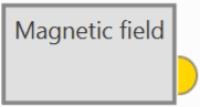
Magnetic Field block
Output
Pin 0: Magnetic field in NED frame as a 5-dimensional real array with the following components:0: Update flag (always 1)
1: North component of magnetic field
2: East component of magnetic field
3: Down component of magnetic field
4: Variance (always zero)
Configuration menu:

Magnetic Field block configuration
North/East/Vertical: The magnetic vector of the mission’s area should be entered.
Declination/Inclination/Horizontal: It is recommended to select ‘Generate magnetic field’ to take the magnetic declination information of the mission area.
The following window will appear to introduce the latitude and longitude of the mission area to generate the magnetic field there:

Magnetic Field block configuration - Generate magnetic field
When generated, this message will appear and the configuration parameters will be automatically updated with the calculated values:

Magnetic Field block configuration - Generate magnetic field message
Magnetometer
Magnetometer sensor block returns the magnetic field being read by the selected sensor in the body frame.
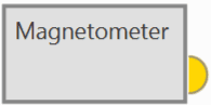
Magnetometer block
Output
Pin 0: Magnetic field in body frame as a 5-dimensional real array with the following components:0: Update flag (always 1)
1: X body component of magnetic field
2: Y body component of magnetic field
3: Z body component of magnetic field
4: Variance
Configuration menu:
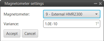
Magnetometer block configuration
Magnetometer: Users must select the desired internal or external sensor magnetometer to be used.
Variance: Means the influence of the parameter on the Navigation filters. The higher the variance, the lower the effect.
This is the only parameter configured indepently from the Mangemtometer selected.
Relative position
Relative position sensor block works in conjunction with the Internest configuration section to configure the Internest system as an ultrasound sensor that calculates the position of Veronte Autopilot 1x.
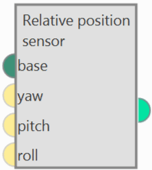
Relative position block
Inputs: The 3 navigation angles (yaw, pitch and roll) of the base platform can be entered.
 base: Base position to which position measurements are relative. Usually a ‘Moving object’ is linked. (Optional) yaw: Yaw of system of reference in which position measurements are received (0 if not connected). (Optional) pitch: Pitch of system of reference in which position measurements are received (0 if not connected). (Optional) roll: Roll of system of reference in which position measurements are received (0 if not connected).
Output
Pin 0: Absolute position measurement.Configuration menu:

Relative position block configuration
Increment of horizontal/vertical variance with distance: With this increment, the further away the Veronte autopilot 1x is from the base, the more variance it is given in a linear fashion.
Horizontal/Vertical sensor variance: Square error of the internest position in xy/z planes.
Note
If the option By device is selected, these parameters are automatically set by the autopilot.
x/y/z: Defines the distance between the Internest system and the center of mass from the base.
Invert measurements (multiply them by -1): If enabled, the measurements shall be multiplied by -1.
More information
These parameters are used in the calculation of the variance for the EKF algorithm by means of the following equation:
\[square \; error = position \; error + increment \; error \cdot distance\]\(position \; error:\) Horizontal/Vertical sensor variance position
\(increment \; error:\) Increment of hotizontal/vertical variance with distance
\(distance:\) Distance to the base
SRTM height
SRTM height sensor block gets the terrain altitude at the current UAV position according to the configured mesh.
SRTM height block
Output
Pin 0: Terrain altitude as a 4-dimensional real array with the following components:0: Update flag (always 1)
1: Valid flag (inside mesh)
2: Terrain height
3: Variance
Configuration menu:
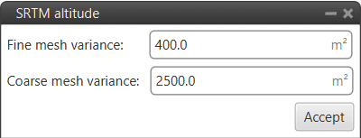
SRTM height block configuration
Fine mesh variance: Variance of the fine mesh. This is the smallest mesh, which contains detailed information on the altitude of the terrain.
Coarse mesh variance: Variance of the coarse mesh. This is the medium mesh with the least detail.
Important
The values to be entered in the configuration of this block must be \(> 0\).
If the configured error values are very large, the EKF will converge more slowly to them or give more importance to other sensors, such as Lidar, to know the height of the terrain.
If these values are small, much more importance will be given to the terrain grid and it will converge faster.
Static Pressure
Static Pressure sensor block returns the static pressure measured by the selected sensor.
Static Pressure block
Output
Pin 0: Static pressure measurement as a 3-dimensional real array with the following components:0: Update flag
1: Pressure
2: Variance
Configuration menu:
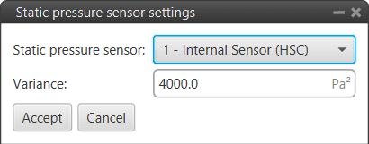
Static Pressure block configuration
Static pressure sensor: Users must select the desired static pressure sensor to be used.
Variance: Means the influence of the parameter on the Navigation filters. The higher the variance, the lower the effect.
This is a parameter configured independently from the Static Pressure sensor selected.