 Control
In this panel all the parameters related to the control of the platform can be found. There are 4 sections, each one showing a different menu of configuration.
Phases
In this section are created (defined but not configured) the Flight Phases that will control the aircraft at different stages of the operation.
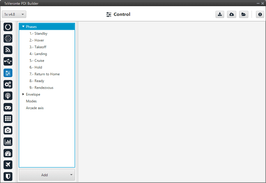
Phases menu
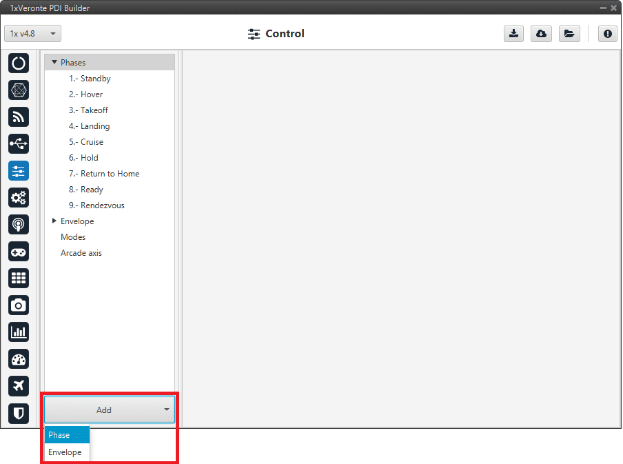
To create a new phase click on Add, and select Phase.
Add phase
The user can select a phase already created or create a new one.
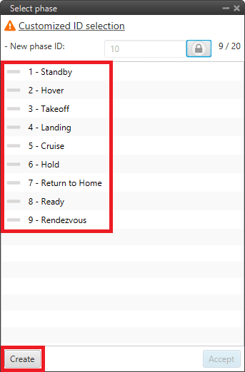
Create phase
In addition, by right clicking on the phase, the user can rename, copy or remove it:
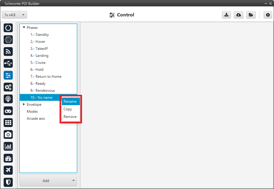
Phase options
Note
The configuration of the phases (guidance and control commands) is done in the Block Programs section.
Envelope
Menu to configure the flight envelope of the aircraft. Here the limits that will not be exceeded during the operation are set.
These limits are respected by the guidance and depend on how the control is implemented.
Warning
Although the acceleration has been limited here, if the control is configured so that the pilot in manual mode can control the pitch angle, this acceleration limit will have no effect.
Envelope
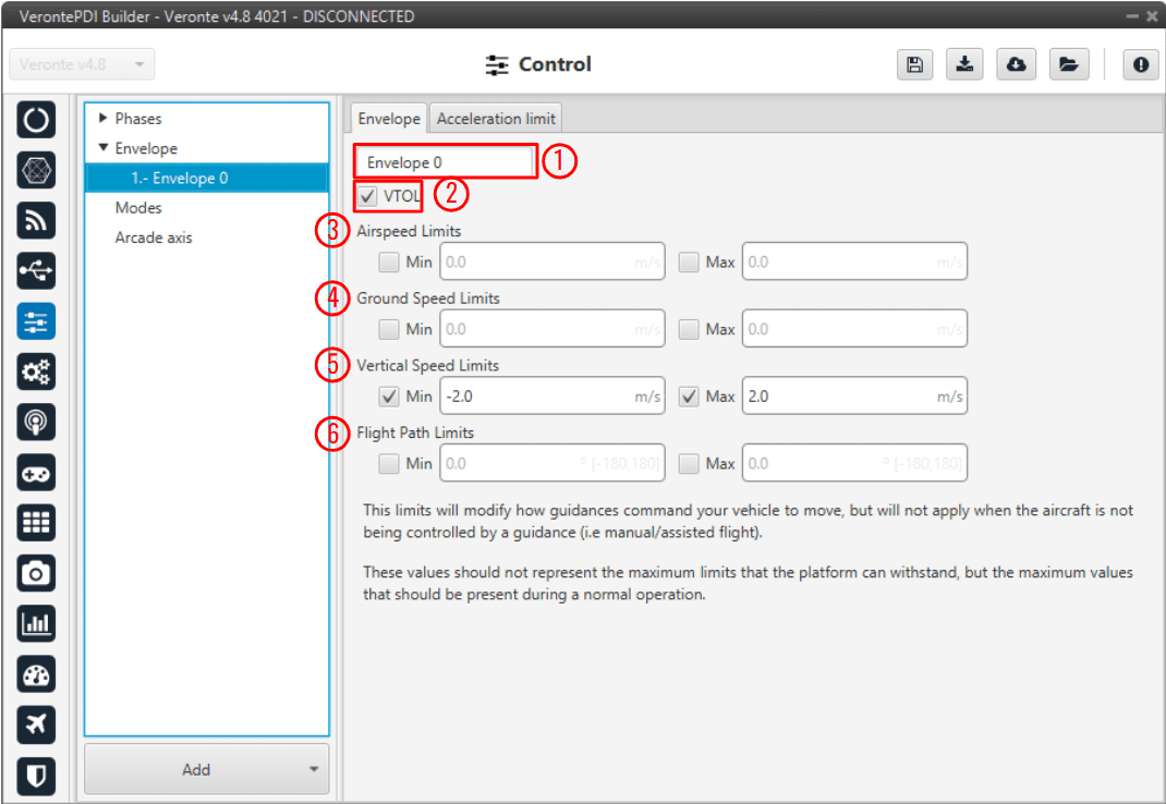
Envelope menu
Envelope name
VTOL: If this option is enabled, when the vehicle reaches the last waypoint of its route (and it is an open path), a hover is done instead of a loiter point.
Airspeed Limits: Limit for the indicated airspeed (IAS). The value indicated here has effect over the “Cruise” guidance, but is overrided if there is a Hold command on the IAS, so the user must be careful with the velocity commands.
Ground Speed Limits: Minimum and maximum ground speed of the platform. In case of strong wind, these parameters set the minimum GS that the aircraft can reach, for lower values than this one the thrust will be automatically increased to gain speed and avoid a point where the platform is stopped in the air.
Vertical Speed Limits: Similar to the previous limit. It sets the minimum and maximun value for the vertical speed of the platform.
Flight Path Limits: Maximum and minimum values for the flight path angle (angle of climb or descent).
It’s possible to insert multiple envelopes (useful for hybrid configurations) by clicking in Add. The change between envelopes can be performed using Automations.
Acceleration limit
In this second tab there are more options to fix the limits (positive and negative direction) of acceleration and jerk in SI units.
Acceleration limits are applied in any phase with position guidance. They modify the desired velocity. The algorithm compares the current desired velocity with thatstored in previous step. There are six values to define.
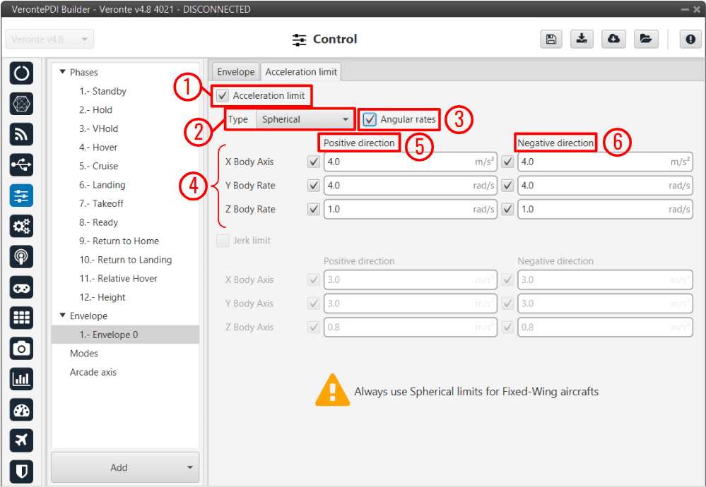
Acceleration limit menu - Spherical frame
The configurable options in this menu are:
Enable/Disable the acceleration limit.
Type: User can choose between Cartesian Body and Spherical.
Cartesian Body is normally used for multicopters or aircraft that allow 3-dimensional movement, while the Spherical type is used for conventional aircraft.
Enable/Disable angular rates: The user also can selected directly angular rates option which allows him set limits in Y body rate and Z body rates.
Axes:
In Cartesian Body the axes refer to the body frame (X Body Axis, Y Body Axis, Z Body Axis).
In Spherical type, the algorithm internally applies limits in module, inclination and azimuth to maintain the limits set by the user in body frame (body frame limits will be turn into spherical limits).
Positive direction: The limit for acceleration. If desired velocity has the same sign as in the previous step, and it is lower (in absolute value) this limit is applied.
For example, if a multicopter is flying in negative X direction, and it has to increase desired velocity in same direction this limit will be applied.
Negative direction: The limit for deceleration. In the case positive direction limit is not used.
The second derivative of velocity (Jerk) imposes another limit in acceleration. It modifies the behaviour of the vehicle.
Depending on values, it’s possible to get more smoothness during guidance. Algorithm ensures that when desired velocity is reached the acceleration value is near 0. As acceleration limits, user can set 6 values (3 for positive direction limit and 3 for negative direction limit).
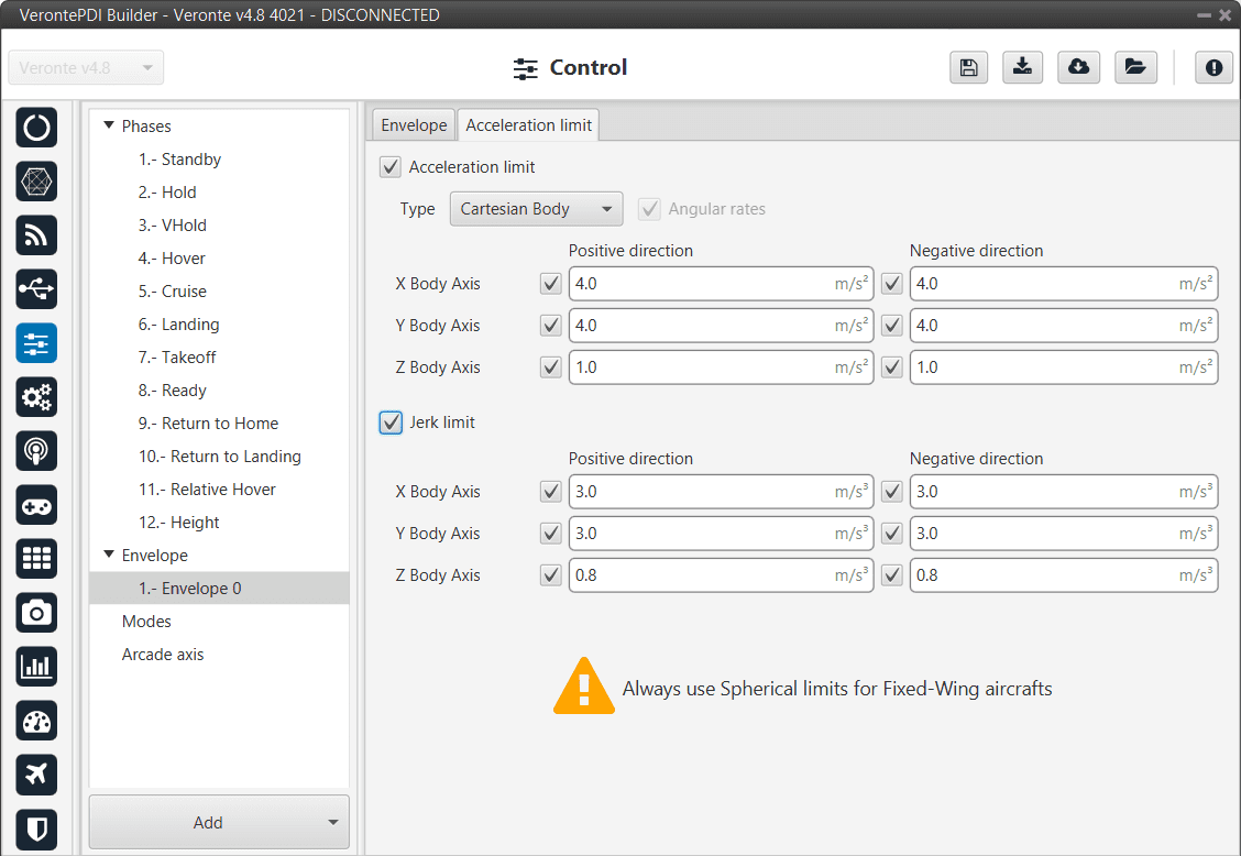
Acceleration limit menu - Cartesian frame
The effects of these limitations are explained below.
First, the acceleration limits are disabled. The stick that controls Thrust is moved and desired velocity change according to this stick command. In Desired velocity chart we can see this effect and in bottom acceleration chart is shown how acceleration is not limited (hight values reached).
Only velocity limit (Thrust)
Now, a limit in acceleration bottom axis is set to 0.1. Now the desired speed grows with a lower slope due to the imposed limitation. Also in the acceleration bottom chart we can see how the value oscillates within the imposed limit.

Acceleration limit (Thrust)
To compare acceleration and jerk, roll axis is chosen. In the first gif below only the first limit is applied.

Acceleration limit (Cartesian frame)
When the jerk limit is also enabled we can see how acceleration (in Y Body axis) does not show peaks, and changes in desired velocity are smoother.

Acceleration limit (Cartesian frame)
Modes
Modes
This menu allows the creation of custom flight modes. The flight modes determine who is in charge of controlling each one of the aircraft control channels.
There are 5 different control modes and it is possible to combine them to create custom flight modes.
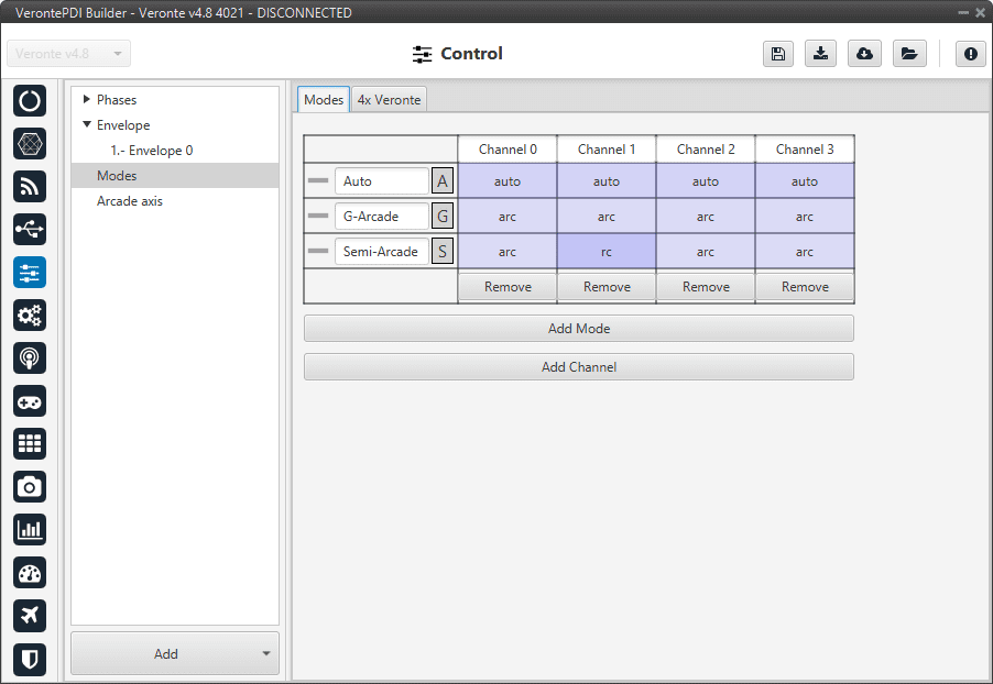
Modes menu
The options available are:
Automatic: The control channel is controlled totally by the autopilot.
RC: The control is totally carried out manually. The movements on the pilot stick imply directly movements on the servo linked to that control channel.
ARC: The autopilot aids the radio controller during the flight, i.e it could be considered as a mix between automatic and manual. The movements on the pilot stick are the input values on the control system, so the pilot commands a desired pitch, roll, IAS, heading and so on, and is the control system who is in charge of making the platform follow those commands.
Mix: In this mode, it is possible to select in which step of the controller will enter the pilot command.
Example
For example, the pitching of an aircraft is commonly controlled with 3 PID being: flight path angle, pitch and pitch rate. In the arcade mode the pilot command will be a desired flight path angle that enters as input of the whole control system, but in the Mix mode is possible to select where we want the command to enter, so the pilot command could be pitch (entering in the second PID directly) or pitch rate (entering directly on the third PID).
The control system will take this input as a disturbance that it wants to discard because the final objective is to match the input of the first PID (a desired flight path angle in this case), so the Mix mode can be used to make small corrections when the aircraft is following a route for example, where we want it to move slightly towards a certain direction by introducing a value directly on the roll PID.
To change any of this options, click on the cell the user would like to change and the next option will be set.
Warning
The name of the mode does not have to correspond to the configuration of the mode.
For example, the user can name the mode as Auto but set the channels as rc (manual):
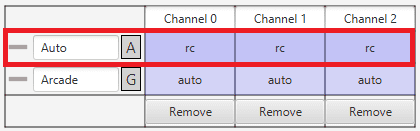
Modes configuration
Moreover, although the mode is set “sensefully” here, in the block configuration (Block Programs) the control does not have to correspond to this.
For example, if a channel is configured as manual (rc) here but then the control is configured so that the stick input does not control the channel, it will be auto control even though manual is specified. See the following example, where for consistency, the blocks in the ‘True’ and ‘False’ cases should be inverted:
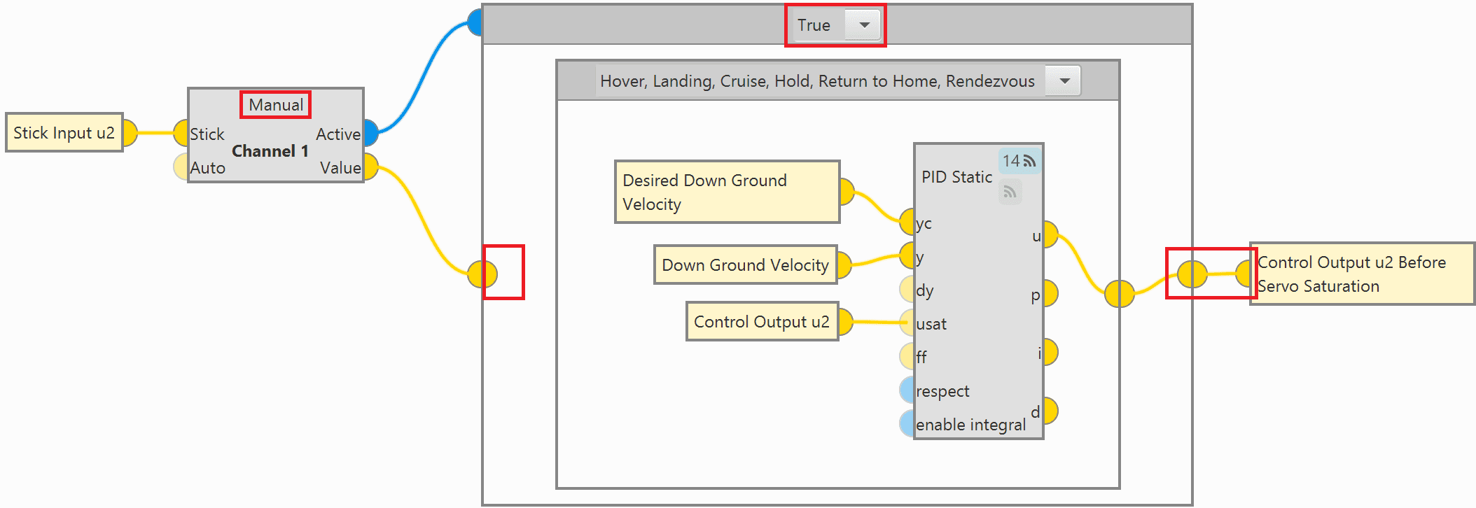
Modes configuration in blocks
So, it is the user’s responsibility to build the configuration correctly. In case of having any questions, the user should contact the support team (create a ticket in the customer’s Joint Collaboration Framework; for more information, see Tickets section of the JCF manual).
4x Veronte
This section allows the user to configure the Autopilot 1x to operate in an Autopilot 4x.
By adding the arbiter address, Veronte Ops will recognise it as part of a 4x unit group, and it will also be possible to do HIL simulations (with Veronte HIL Simulator) with this 4x group.
Note
If the arbiter address is set to 999, there is no arbiter.
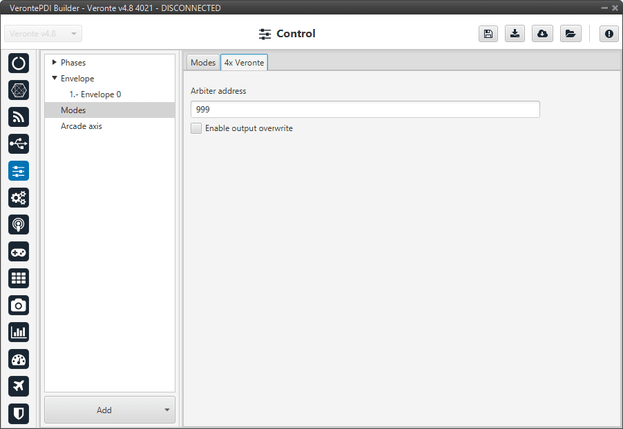
4x autopilot menu
To allow the output to be overwritten, the checkbox must be checked.
By enabling it, a table can be created in which columns correspond to each 1x Autopilot and rows to the different channels. For each channel and autopilot, a variable should selected.
This option must work in conjunction with the AP Selection block. In this block, the output “Value” will be the variable associated to the selected channel and autopilot.
In the “Selected” field, the selected variable is 4xV Veronte selected, which indicates which Autopilot 1x is selected. This information is received from the status message from the arbiter (for more information on the this status message, see CAN Bus protocol section) of the 4x Software Manual.
An example configuration is presented below:
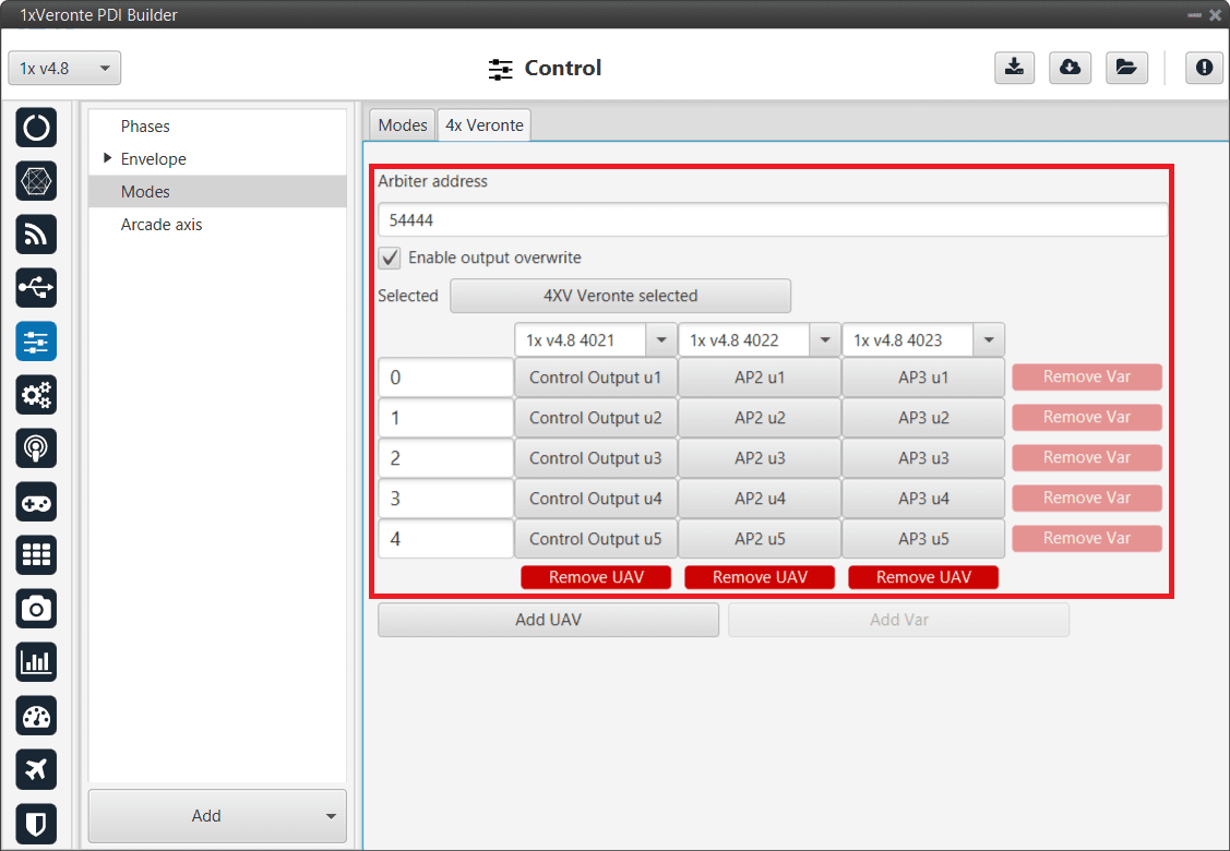
4x autopilot menu - Example of use
Arcade axis
The Arcade Axis menu enables the option of changing the center of the system axes. This option is used to create axis systems referred to a certain point or direction, for example, it is uselful when the pilot wants all movement to be made with respect him (Ground axes). In this way, if the pilot command a turn right, the aircraft will turn to the right of the pilot, instead the right of the aircraft (Body axes).
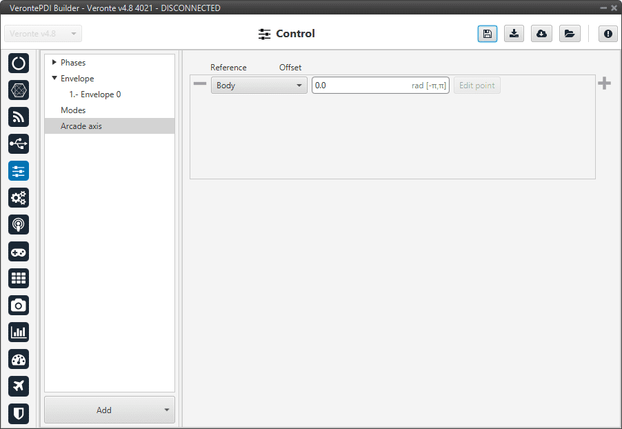
Arcade axis menu
It is possible to add as many axes system as desired, being able to choose between the following types:
Body: Fix the axes in the UAV. It is standard for the pilot.
Ground: Fix the axes in the 1x GND unit.
Point: Fix the axes in a point that user defines.
Heading: Fix the axes in the the heading defined.
Desired heading: Fix the axes in the desired heading.
Tangent direction: Fix the axes in the tangent direction of the designed path.
Desired yaw: Fix the axes in the desired yaw.
An automation can be used to select an Arcade Axis in flight, see Actions in Automations section.