 Stick
In this section, the stick configuration on 1x PDI Builder is explained.
This allows the user to set up to four transmitters and one virtual stick. The autopilot’s capabilities allows it to receive information from four different transmitters at the same time plus transforming some values into a virtual stick.
The content presented in the next menus covers:
Setting of the transmitter’s parameters.
Definition of exponential response-curves for the desired channels.
Trimming of the channels’ neutral position.
Setting of the data receiving port on the autopilot.
Definition of a virtual stick.
Transmitter (1-4)
The wired connected transmitters are configured through the following tabs.
PPM
This tab provides the options to configure a Pulse Postion Modulation (PPM) radio controller to control the platform fitted with the autopilot.
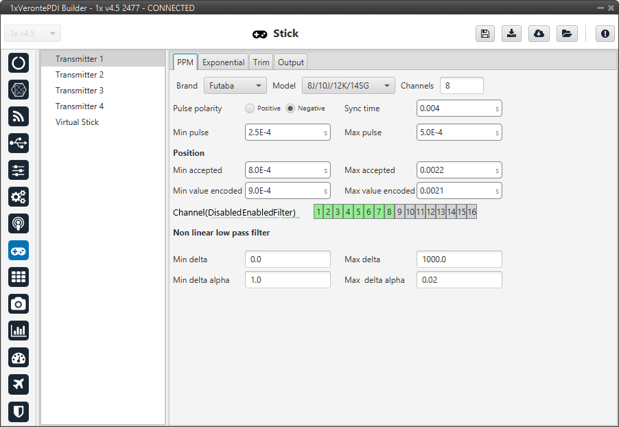
Stick - PPM menu
Brand, Model and Channels: 1x PDI Builder has been configured to provide the user with the expected parameters to configure different transmitters models.
Brand
Models
Channels
Futaba
8J/10J/12K/14SG
8
12K/14SG
12
T18SZ
8
Jeti
DC 16/DC 24
16
FrSky
Taranis X9D
8
Horus X12S
8
TBS
Croosfire
8
Embention
Stick Expander
16
Custom
-
-
Custom: If the user’s transmitter is not among those mentioned above, choose this option and replace the parameter values with the appropriate ones.
Pulse polarity: Indicates the pulse polarity:
Positive: Default signal is low and goes up to high.
Negative: Default signal is high and goes down to low.
Sync time: Minimum time on the PPM output till the next frame. It tells the receiver to reset its channel counter.
Minimum/Maximum pulse: Pulse length, it depends on the system and it is a constant value (usually 0.2-0.5 ms).
Position
Minimum/Maximum accepted: Pulse length accepted for each channel. Standard for R/C servos uses a pulse of 1 ms for the maximum position at one end, 1.5 ms for the midpoint and 2 ms for the maximum position at the opposite end.
Minimum/Maximum encoded: If there is noise and the signal is varying around the minimum/maximum values accepted, 1x autopilot will encode those values to the ones set here. For instance, a pulse length between 0.8-0.9 ms will be considered as one of 0.9 ms.
Channels: Sets the number of channels accepted. Besides, it is possible to Disable/Enable/Filter each channel individually.
Non linear low pass filter
Minimum/Maximum delta: Default parameters are recommended.
Minimum/Maximum delta alpha: Default parameters are recommended.
The figure below shows the PPM signal that arrives to Veronte Autopilot 1x:
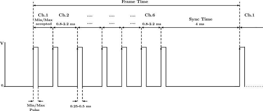
PPM signal
Exponential
The second tab allows the user to define an exponential stick response for every channel.
The allowed inputs range from 0 to 1 and there is a graph showing the generated response curve, as can be seen in the figure below.
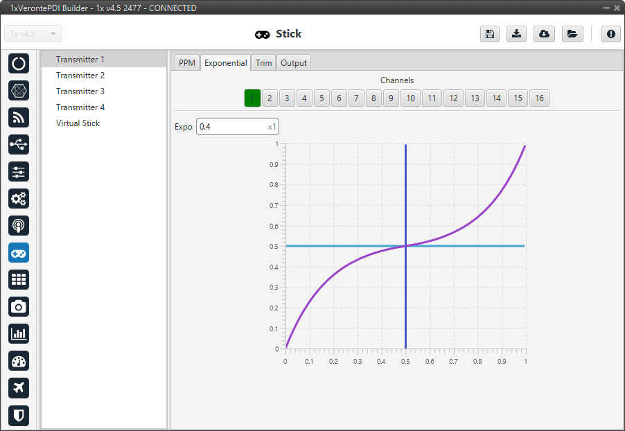
Stick - Exponential menu
The X axis of the graph corresponds to the stick input and the Y axis is the result of applying the exponential function to that stick input.
Trim
The third tab available is the Trim option.
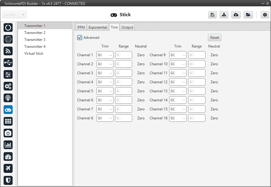
Stick - Trim menu
By enabling the Avanced option, the user can set the expected trim values manually. The user should have a deep knowledge on its transmitter if this option is selected.
Finally, on the right hand side, the Reset button puts every parameter back to 0.
Output
In this menu the user sets the receiving port and process the incoming commands. Once the stick has been configured, the commands that arrive at the ground autopilot have to be sent to the air unit.
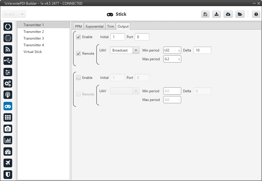
Stick - Output menu
In this menu, the following parameters can be configured:
Enable.
Initial Channel at destination: The user indicates to which channel of the air autopilot will be sent the first channel received in the ground unit. The channels arrive at the platform in order and without spaces between them.
For example, if at the GND channels 6,7,8,9 and 10 are enabled, the AIR will receive channels 1,2,3,4 and 5. Therefore channel 6 of the stick will be channel 1 in the AIR configuration.
Port: If more than one transmitter is configured, each transmitter must be configured on a different port. This has to match the port set on the air unit.
Remote: It has to be enabled if the user wants to allow the delivery of the commands to the platform.
UAV: The address of the UAV that receive the commands has to be indicated. The following options are available:
App 2: Veronte Ops address.
Broadcast: The commands are sent to all units on the network. We recommend this option.
Veronte v4.X XXXX: The address of a specific air unit.
Min period: As the period is the inverse of the frequency, this is the maximum frequency. Therefore, to give the pilot more control, this is the frequency that is set when the stick is commanding. We recommend 0.02s.
Max period: As the period is the inverse of the frequency, this is the minimum frequency. Thus, to free up bandwidth, this is the frequency that is set when the stick is idle. We recommend 0.2s.
Delta: This parameter determines whether the frequency is set to the minimum or maximum period set above.
If 1x Autopilot detects a change above the delta value, the frequency goes to the maximum frequency (minimum period). While if the changes are less than this value, it switches to the minimum frequency (maximum period). We recommend 10.
Note
An example of the Stick integration can be found in the Integration examples section.
Virtual Stick
In this menu a virtual stick can be defined. It can be useful when:
Testing the autopilot configuration (not flight tests).
Using a USB stick. Please find more information about this in the USB -> Integration examples section.
The information of a stick is received through a different channel than PPM, so that the virtual stick will process that information and input it into the system.
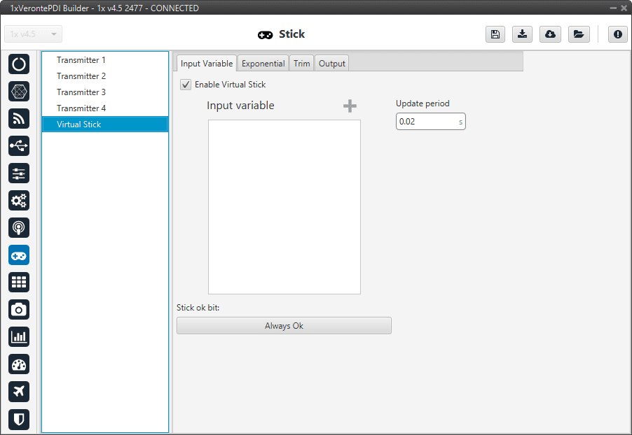
Virtual stick menu
In this menu the user can configure:
Enable Virtual Stick
Input variables: Place here the variables containing the stick information. It is not necessary when using a USB stick or simply virtual stick.
Update Period: Configure the period required. We recommend 0.02 s.
In addition, a virtual stick widget must be configured in Veronte Ops. Please find more information in the Stick -> Widgets section of the Veronte Ops manual.
The tabs Trim and Output are the same as the Transmitter ones, so refer to the Transmitter menu for more information.
Note
An example of the Virtual stick integration can be found in the Integration examples section.