 UI
UI
In this menu, the user can manage operation elements, system variables and the geoid world mesh.
Operation elements
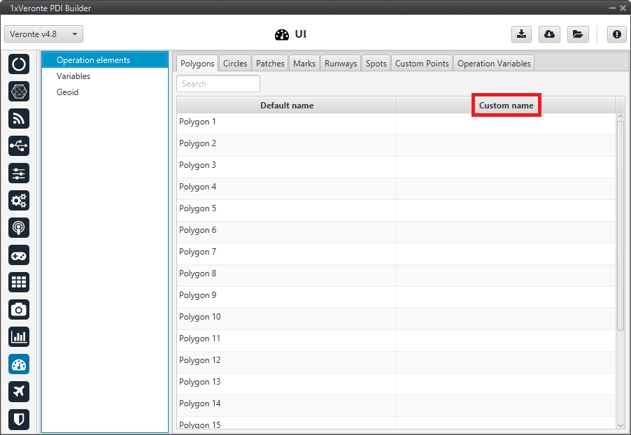
In this section, the user can rename operation elements. These are variables that have no value until an operation is performed, e.g. cruise speed and altitudes, marks to initiate landing, the route, etc.
In addition, they must first be renamed in this section, so that they can then be referenced in the setup, as in Automations (see Automations section), and then defined in the operation, in Veronte Ops (visit Veront Ops manual).
Operation elements are divided into 8 different types:
Custom Points: An operation custom point is a waypoint, a position variable (x,y,z) that can be used as a reference.
Patches: A patch establishes a path that the UAV can fly to, they make up the route. Therefore patches include waypoints, segments, arcs and orbits.
Marks: A mark is a reference that is placed in a patch and when the uav reaches it, an action takes place.
Polygons: A polygon is a detection area.
Circles: A circle is a circular polygon.
Runways: These are the runways used during the take-off and landing phases.
Spots: A spot is a kind of runway with an initial point, direction and azimuth.
Operation variables: An operation guidance point is a value of the operation, such as the cruise speed.
Operation elements section
Variables
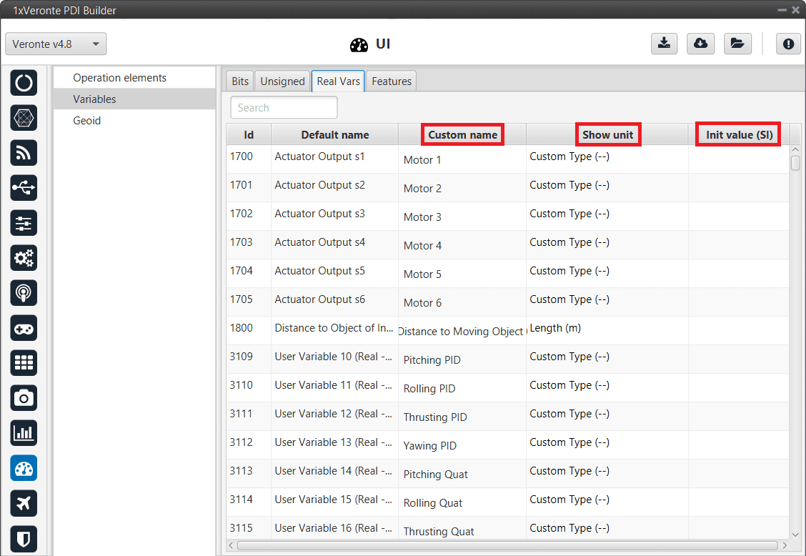
In this section, the user can find the name of all system variables, as well as their units and initial values. This is very useful, for example, in the case of ‘User Variables’.
Variables are divided into 4 different tabs:
Bits: Bits variables, 1 bit.
Unsigned: Unsigned integer variables, 16 bits.
Real Vars: Real Variables, 32 bits.
Features: Features variables, 64 bits.
Note
There are 300 User variables available for each class (Bits, Unsignet and Real Vars).
Variables section
To set a custom name for one of the system variables:
Click on the Custom Name cell of the desired variable and introduce the new name for it.
When the name is introduced press Enter to store the name on the system.
Press Save to save all changes.
Error
In this version, there is a maximum amount of characters that the user can use to rename variables, i.e. there is no limit per se but there is a maximum size of the configurable (xml size).
Besides changing their name, the user can also configure the measurement units of the variables, as well as the initial value (expressed in SI units) they will have each time the system (re)starts, using the Show Units and the Initial Value (SI) cells.
By right-clicking on the Show Units cell, the user can select the desired units.
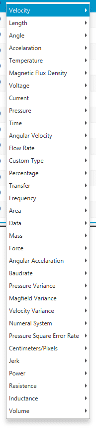
Variables units
The table below shows all the available units in 1x PDI Builder.
Variable Type |
Units |
|---|---|
Velocity |
[m/s] [kt] [km/h] [mph] [ft/s] [mm/s] [ft/m] |
Length |
[m] [km] [mi] [NM] [yd] [ft] [in] [cm] [mm] |
Angle |
rad[-π;π] °[-180;180] °[0;360] [° ‘ “] [rad] rad[0;2π] ° |
Acceleration |
[m/s²] [ft/s²] [in/s²] [g] |
Temperature |
[K] [°C] [°F] |
Magnetic Flux Density |
[T] [mG] [gauss] [nT] |
Voltage |
[V] [mV] |
Current |
[A] [mA] |
Pressure |
[Pa] [kPa] [bar] [mbar] [psi] [mmHg] [at] [atm] |
Time |
[s] [min] [h] [μs] [ms] [Time] |
Angular Velocity |
[rad/s] [rad/m] [rad/h] [rps] [rpm] [rph] [°/s] |
Flow Rate |
[m³/s] [gal/s] [gal/h] [l/s] [l/h] |
Custom Type |
[- -] |
Percentage |
[x1] [%] |
Transfer |
[pkts/s] |
Frequency |
[Hz] [mHz] [kHz] |
Area |
[m²] [cm²] [mm²] [km²] [mile²] [ft²] [yd²] |
Data |
[bit] [byte] [KB] [GB] [bytes/s] |
Mass |
[kg] [g] [tonnes] [lbs] [oz] |
Force |
[N] [kN] [lbf] [pdl] |
Angular Acceleration |
[rpm/s] [rad/s²] [rad/m²] [rad/h²] [°/s²] [°/m²] [°/h²] |
Baudrate |
[Bd] [kBd] [MBd] |
Pressure Variance |
[Pa²] |
Magfield Variance |
[T²] |
Velocity Variance |
[(m/s)²] [(cm/s)²] [(mm/s)²] |
Numeral System |
[bin] [octal] [dec] [hex] |
Pressure Square Error Rate |
[Pa²/s] |
Centimeters/Pixels |
[cm/pixel] |
Jerk |
[m/s³] |
Power |
[W] [kW] [Kgm/s] [erg/s] [CV] |
Resistence |
[Ω] |
Inductance |
[H] |
Volume |
[m³] [dm³] [mm³] [L] [mL] |
Geoid
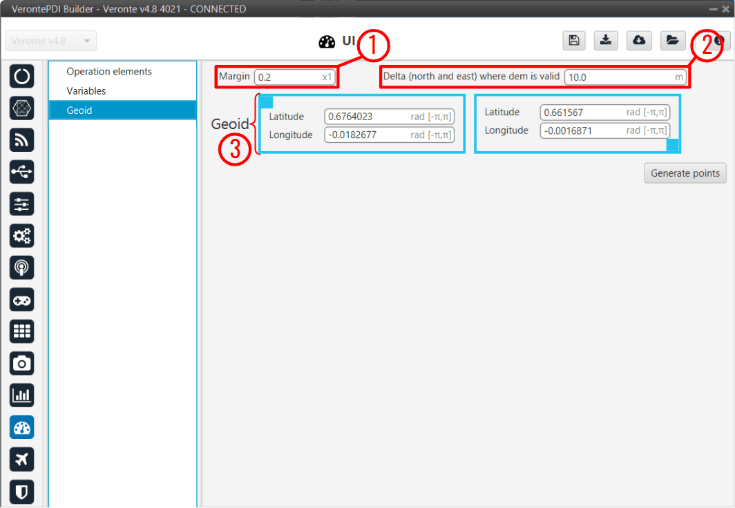
In this section, the user can define the world mesh which provides the geoid altitude.
Geoid section
Margin: This is the percentage at which the system will recalculate the mission if the route is displaced. In other words, if the mission is displaced 60% out of the area and the margin is set to 80%, the mission will be not recalculated. If the mission is 81% (or more) away from the previous one, the system will recalculate the mission. A low level (or zero) margin means more terrain profile precision but the system will have to recalculate the meshes more times (or each time) when the mission is modified.
Delta: The distance to the ground (AGL) may be measured through two or more systems. Usually, an altimeter like a LIDAR in conjunction with the GPS signal and the meshes information are used. During flight, it is possible that the GPS position error is large enough that the height provided by the meshes does not correspond with the actual position. In order to avoid problems, the Delta parameter can be defined. This parameter defines a circumference radius where both systems will be used. If the estimated position error is bigger than the delta parameter, only LIDAR data will be used.
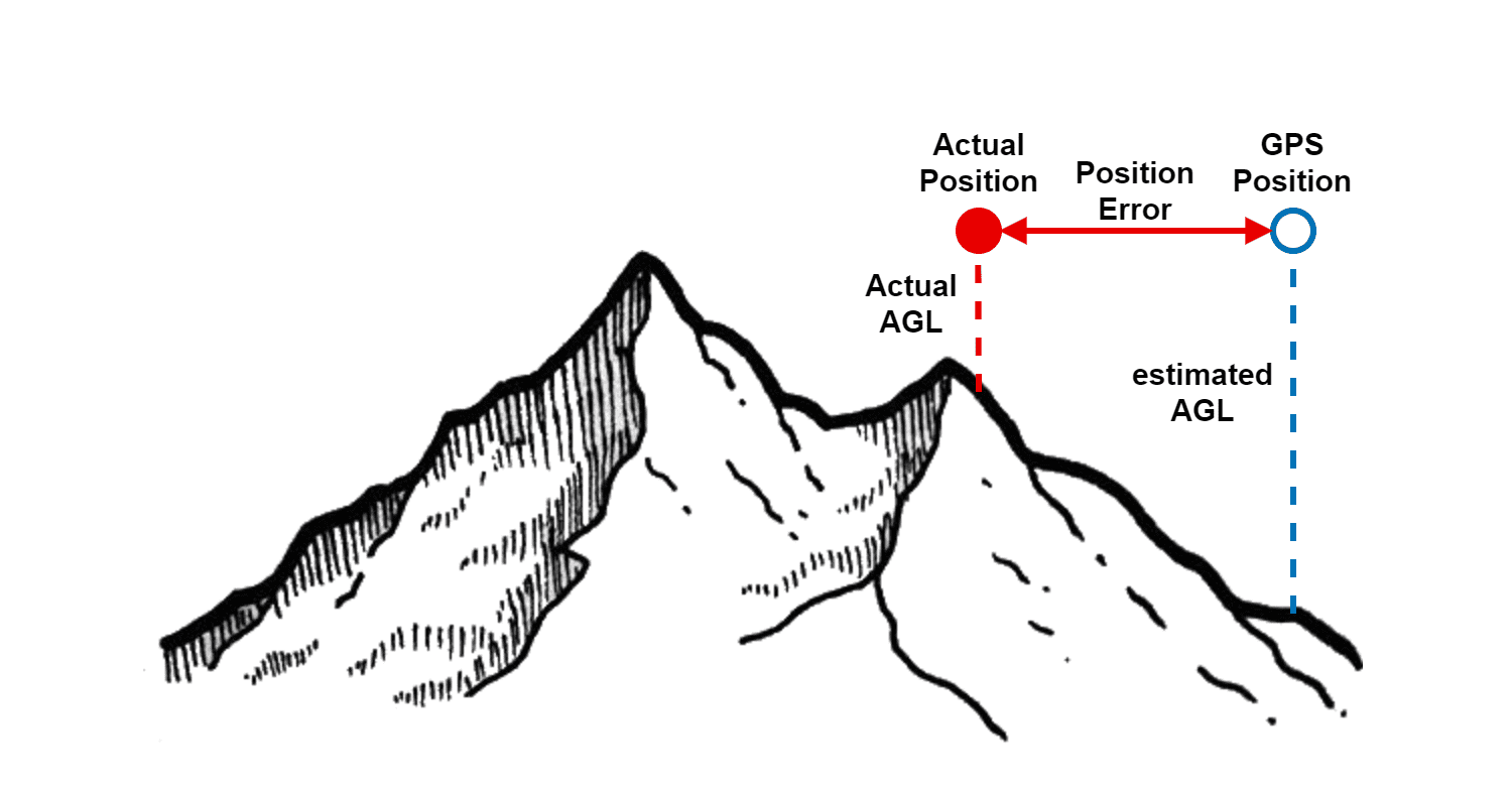
Delta Parameter
Geoid: World mesh which provides the geoid altitude. The user must place and adjust the mesh manually, the coordinates of each upper left corner and lower right corner of the meshes’ rectangle must be introduced. In general, increasing meshes size will mean lower area definition. And greater resolutions smaller meshes, because it implies heavier data files.
Warning
Check that meshes position are over the mission area before flying, especially if carrying out an operation in mountainous terrain.