Digital Input
GPIO pins can work as Digital Input or Output as well as PWM. In order to configure some custom sensors such as a Stick PPM, Pulse sensor or RPM sensor pins are reserved, which correspond to pins 55-58. These pins can also be used as Digital I/O.
Sensors using a Digital Input are configured in this menu.
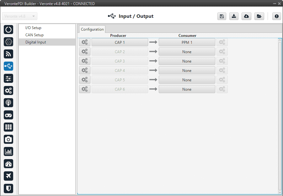
Digital Input section
The process to configure a device can be done as follows:
Select and configure a Producer. There are 6 possible producers: CAP 1 - 6.
Press on the configuration button (
 icon) and a new pop-up window will show.
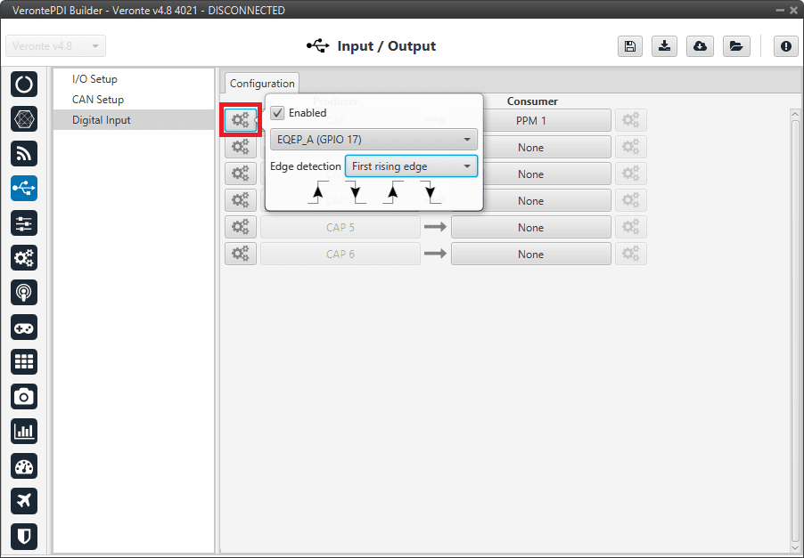
Digital Input - Producer
In the pop-up window, users can check:
That this producer is enabled.
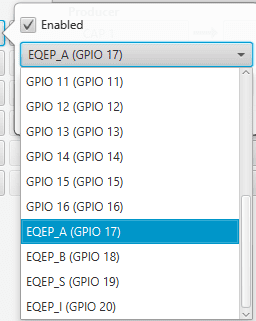
Which pin this CAP is associated and, therefore, to which device is connected. It is possible to select these pins. Pins available are GPIO 1 to 16, and EQEP A, B, S and I. When using the harness provided by Embention the transmitter Digital Input is connected to the pin 55 (EQEP_A) with pin 49 as Ground.
Digital Input - CAP
How the pulses are read and transformed into a digital signal (how they are processed). That can be configured with the Edge detection option.
By clicking on the drop-down menu, the following options can be selected:
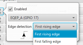
Digital Input - Edge detection option
First rising edge: With this option, when the rise of the pulse is detected, the data will start to be stored. Recommended when consumer is PPM or Pulse.
First falling edge: With this option, when the fall of the pulse is detected, the data will start to be stored.
Note
By clicking on the arrows, it can also be configured as desired. For example, if the user has selected the ‘First rising edge’ option, but clicking on the arrows gets the arrow scheme of the ‘First falling edge’ option, the name of the edge detection will not be ‘First rising edge’, but will become ‘First falling edge’.
Digital Input - Edge detection option
Click on the Bind button to select the type of Consumer, it is possible to choose among a PPM 1-4 (Stick PPM), RPM 1-6 (RPM sensor) or Pulse 1-4 (Pulse).
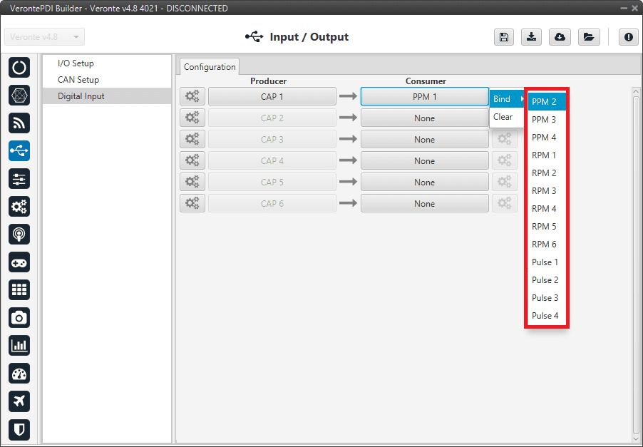
Digital Input - Consumer
PPM 1-4 selected: PPM is configured in the Stick menu.
RPM 1-6 selected: The variables in which the information read here is stored are ‘RPM 1-6’. For more information on the configuration of RPM, see the RPM section.
Pulse 1-4 selected: The variables in which the information read here is stored are ‘Captured pulse 1-4’. It is possible to configure it clicking on the configuration button (
icon):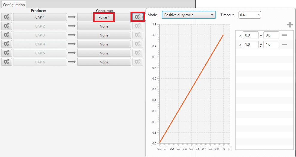
Digital Input - Pulse
In the pop-up window, users will find the following options for configuration:
Mode:
Positive pulse duration: The period of the pulse is obtained. It takes the time in ‘High’ state.
Negative pulse duration: The period of the pulse is obtained. It takes the time in ‘Low’ state.
Positive/Negative pulse duration
Positive duty cycle: The duty cycle. It takes the time in ‘High’ state.
Negative duty cycle: The duty cycle. It takes the time in ‘Low’ state.

Positive/Negative duty cycle
Time out: This defines the time to consider that no signal is received.
Function: Here the user can customise a function to handle the values. Normally, a function is set with the points [0,0] and [1,1], so no transformation is applied, input = output. However, the user can configure it as desired.
Example
Let’s imagine that First rising edge has been selected as the edge detection option in Producer and the pulse that 1x has to read is a square signal with a period of 2 seconds and a duty cycle of 25% (see image below).

Signal generated
On the other hand, if Positive pulse duration is selected as Consumer and it is configured as in the previous image (Digital Input - Pulse), the value obtained in the variable Captured pulse (Captured pulse 1 in the following example) will be 0.50s, this is because it is the period of the “Positive pulse” of that pulse.
However, if Positive duty cycle is selected as Consumer, the value obtained in the variable Captured pulse (Captured pulse 2 in the following example) will be 0.25, this is because it is the positive duty cycle of that pulse.
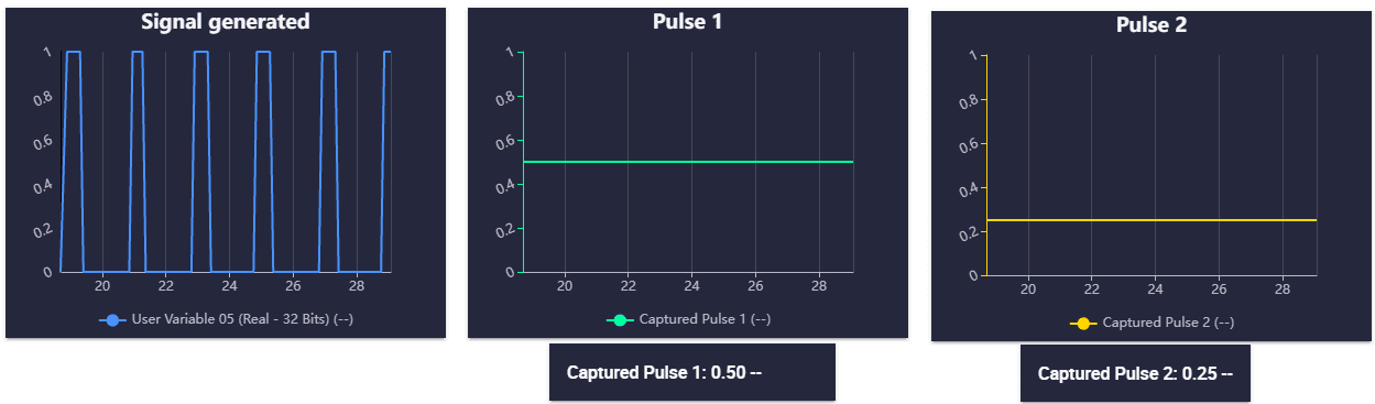
Digital Input example