CAN Setup
A CAN (Controller Area Network) Bus is a robust vehicle bus standard widely used in the aviation sector. 1x autopilot is fitted with two CAN buses that can be configured independently.
The structure of a CAN message can be seen in the following image:
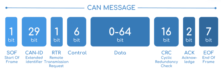
CAN message structure
Only the ID is introduced in the system, the rest of the message layout is already coded. The data field is the one build by the user to send, and parsed when received.
The baud rate of both CAN buses can be configured in the Mailboxes section.
The steps to be followed from the moment a CAN message arrives at or is sent from the 1x autopilot are described in the CAN communication -> Integration examples section.
Configuration
This menu allows the configuration of communications between different devices.
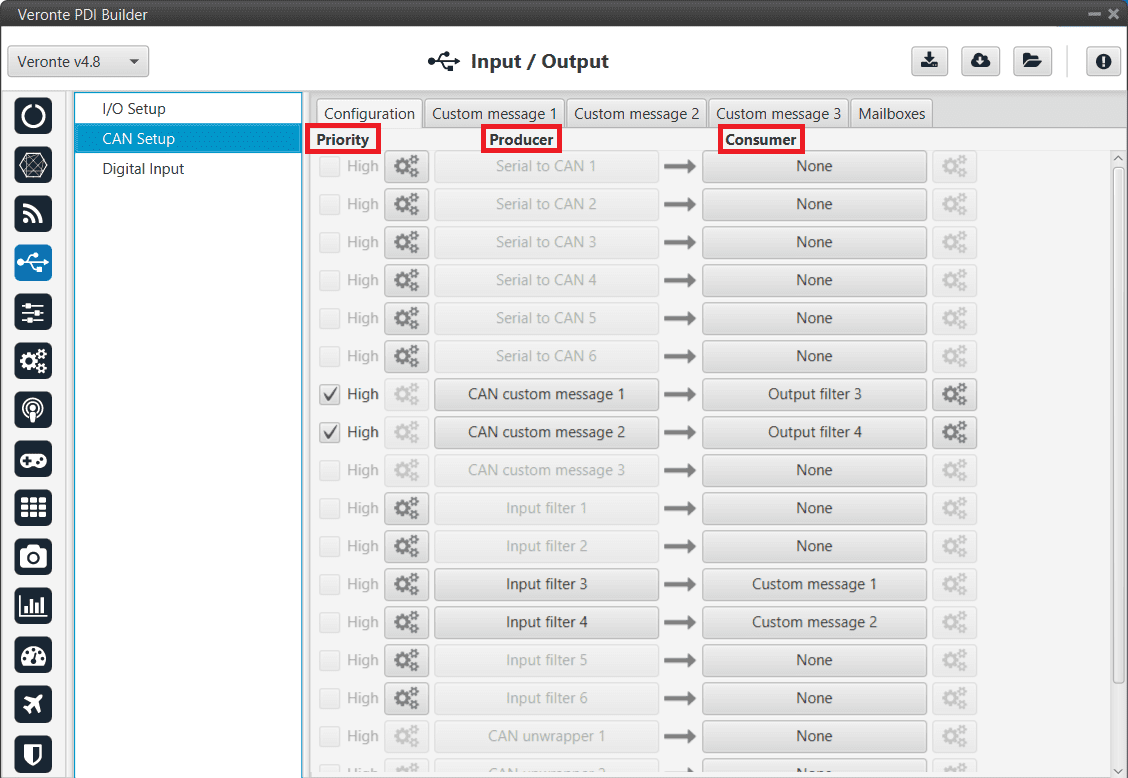
CAN configuration section
In this menu, the user can find the same ‘columns’ (Priority, Producer and Consumer) as in the I/O Setup menu.
Warning
In CAN, in Low state the specified period is not guaranteed but in High state it is.
However, only those messages that are critical for external devices should be set as high priority, as this may disrupt the proper functioning of Veronte Autopilot 1x.
On the one hand, 1x autopilot has the producers shown below:
Serial to CAN: Serial messages over CAN output, it has to be connected to I/O Setup consumer. It can be configured in the configuration button (
 icon), a pop-up window will appear:
Warning
For correct communication, mark it as High priority (with the Priority checkbox).
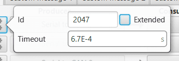
Serial to CAN configuration
Id: CAN Id must be set and it is used to identify messages. The value set has to be decimal format.
Extended: If enabled, the frame format will be this, ‘Extended’, i.e. with a 29-bit identifier. Otherwise, the frame format ‘Standard’ (11-bit identifier) is set by default.
Time out: This is the threshold time between receptions to consider that it is not being received correctly.
CAN custom message: CAN custom messages transmission. They are configured in the next section, see Custom Messages.
Input filter: CAN input filters. Those CAN messages received in one filter can no longer be received in subsequent filters. Input filter must be configured in the configuration button (
icon), a pop-up window will appear: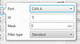
Input filter configuration
Port: It is required to configure the CAN bus from which it listens, the user can choose between CAN A, CAN B or BOTH.
Id: CAN Id must be set and it is used to identify messages. The value set has to be decimal format.
Mask: Here a CAN Id mask can be set to filter messages. The mask defines the bits that should match.
Filter type: The options available are Standard, Extended and Both.
Attention
Make sure that the mask is set properly to be able to receive the desired CAN messages.
CAN unwrapper: This undoes the ‘CAN wrapper’ action, it has to be connected to I/O Setup consumer.
CAN GPIO remote: CAN messages to GPIO peripherals such as CEX and Arbiter. It can be configured in the configuration button (
icon), a pop-up window will appear: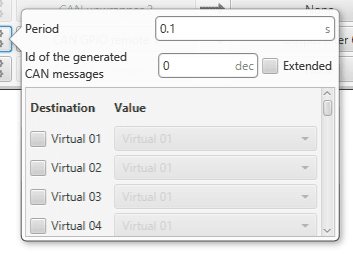
CAN GPIO remote configuration
Period: It is the period of sending messages.
Id of the generated CAN message: CAN Id must be set and it is used to identify messages. The value set has to be decimal format.
Extended: If enabled, the frame format will be this, ‘Extended’, i.e. with a 29-bit identifier. Otherwise, the frame format ‘Standard’ (11-bit identifier) is set by default.
Destination: Here the user select the destination CEX pins.
Value: The user must select the 1x pin to be connected to the CEX pin.
On the other hand, the consumers are the following:
CAN to serial: This undoes the ‘Serial to CAN’ action, it has to be connected to I/O Setup producer.
Warning
For correct communication, mark it as High priority (with the Priority checkbox).
Custom message: CAN custom messages reception. They are configured in the next section, see Custom Messages.
Output filter: CAN output filters. The user can choose between CAN A, CAN B or BOTH in the configuration button (
icon).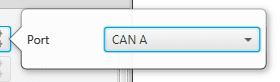
Output filter configuration
CAN wrapper: CAN messages over serial output, it has to be connected to I/O Setup producer.
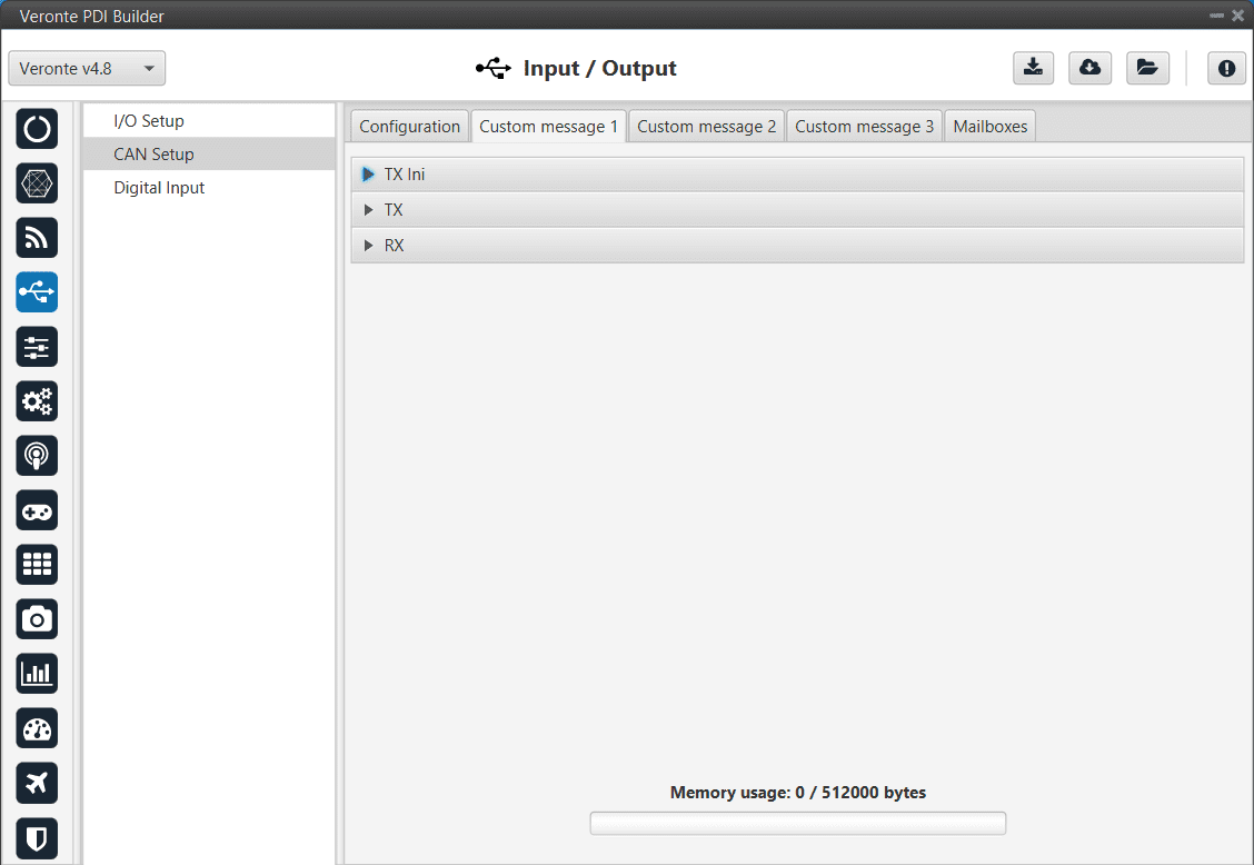
Custom Messages
In the custom message tabs (there are 3 available), the user chooses the variables to be sent/received over the CAN buses. The following elements can be configured:
TX Ini: Used to configure transmitted messages that are only sent once at the beginning of the operation (sent when the autopilot boots up). They can be used to initialize some devices.
TX: Used to configure transmitted messages.
RX: Used to configure the reception messages (where they are stored).
Warning
The maximum capacity of a CAN message is 64 bits (8 bytes), so to send more information it must be divided into several messages.
1x autopilot has a CAN limitation of 40 TX messages per Custom, 40 TX Ini messages per Custom and 80 RX messages per Custom.
In addition, there is a limit shared with all Customs, including RS Custom Messages:
Maximum number of vectors (fieldset): 104
Maximum number of fields: 2000
CAN Custom Message section
TX Messages
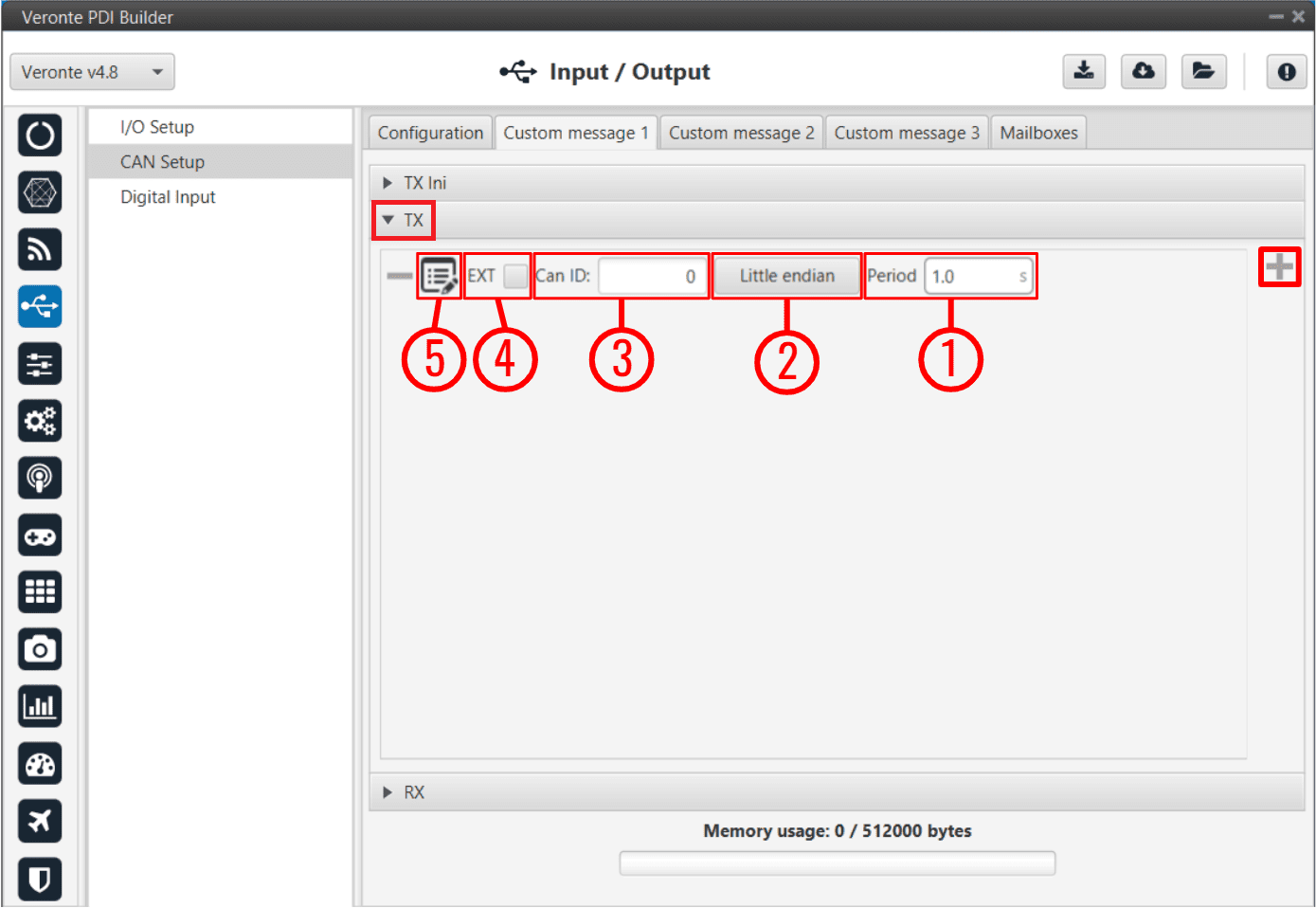
CAN Custom Message - TX
In order to add a new custom message the user needs to press ![]() and a new element will be added into the panel.
and a new element will be added into the panel.
Period: This is the time in seconds between TX messages delivery.
Endianness: The endianness of the message must be configured, which indicates how the bytes that it contains are sent/read:
Big endian: Set the value from left to right.
Little endian: Set the value from right to left.
Mixed endian: Some devices use this format. If users need to configure it, please contact the support team (create a ticket in the customer’s Joint Collaboration Framework; for more information, see Tickets section of the JCF manual).
Can ID: 11-bits (Standard) or 29-bits (Extended) ID used to identify TX messages. The value set has to be decimal format.
EXT: Enables the frame format with a 29-bit identifier (Extended).
Edit message button (
 icon): Displays the menu to configure how the bits/bytes of the message are divided and sent.
There are six different options that can be added when setting up a custom message: Variable, Checksum, Matcher, Skip, Parse ASCII and Position.
The explanation of how to configure these different types of custom messages is detailed in the following section \(\Rightarrow\) Custom Messages types.
RX Messages
The procedure is similar to the one followed in TX messages.
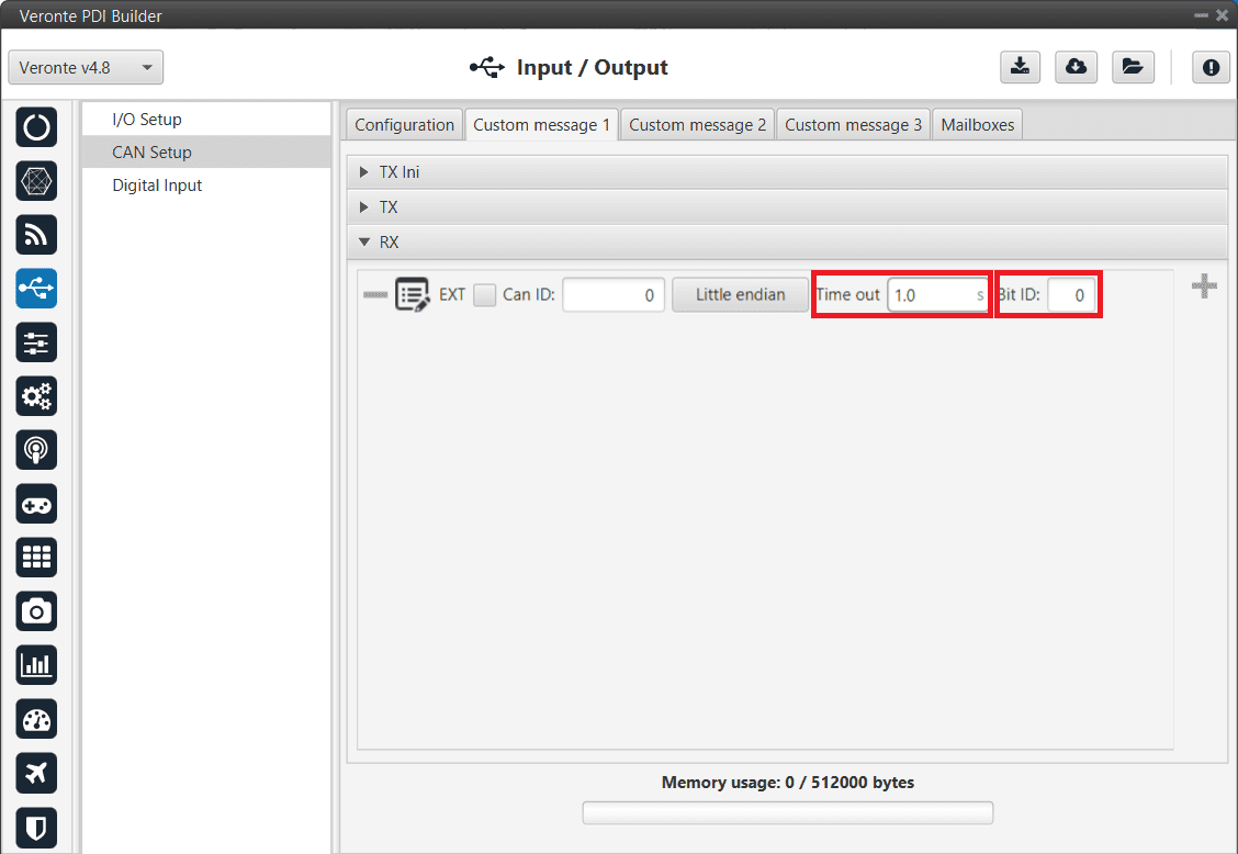
CAN Custom Message - RX
The options and parameters to configure here are almost the same as those described in TX Messages above, except for one:
Can ID: The custom message needs to have the expected ID with which the external device/sensor is going to be sending information.
Attention
It is important to configure a mailbox for every single reception ID. See Mailboxes for more information.
Also, unlike TX messages there are two additional variables per message:
Time out: This is the threshold time between receptions to consider that it is not being received correctly. For example, if time out is set to 1s and it passes more than 1s since the last reception, the bit ID will be set to false.
Bit ID: The user bit selected in Bit ID box will be true if the message is being received correctly.
Warning
Pay attention that the user bit selected in Bit ID is not in use for another task.
The custom message structure needs to match the reception data-format. User variables (real - 32 bits , integer - 16 bits or boolean - 1 bit) need to be used to store that data.
Mailboxes
Here the user can modify the mailboxes from the selected CAN bus (CAN A or CAN B).
When 1x autopilot is going to receive data on the CAN Bus, it is mandatory to configure a certain number of mailboxes. However, it is also necessary to have at least 1 mailbox for transmission (TX).
In order to add a mailbox, press the ![]() icon.
icon.
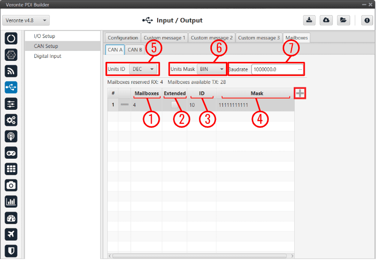
Mailboxes section
Mailboxes are required to store the data received until 1x autopilot reads it and it is necessary at least one mailbox per RX message. 1x PDI Builder allows up to 32 mailboxes.
Warning
Do not use all 32 mailboxes for RX, leave at least one free for TX.
The configurable parameters when adding a new mailbox are:
Mailboxes: Number of mailboxes assigned to that ID.
Extended: Select this option for 29-bit IDs.
ID: 11-bits (Standard) or 29-bits (Extended) ID used to identify RX messages. The value set can be defined in different units, this is configured in (5).
Mask: This filter is configured for reception messages; received data will be stored on mailboxes where message ID coincides with mailbox ID.
Mask adds some flexibility on the reception, when comparing message with mailbox data, only the value of binary digits configured as 1 on the mask will be taken into account. The value set can be defined in different units, this is configured in (6).
For example, for a configuration mask: 11 000 and ID: 10 110 all incoming messages addressed to 10 XXX will be received in this mailbox.
Units ID: Units available are Decimal, Hexadecimal or Binary.
Units Mask: Units available are Decimal, Hexadecimal or Binary.
Baudrate: CAN Baudrate can be configured here.
Warning
If any mailbox is full and another message arrives, the new message is discarded.