Custom Messages types
There are six different options that can be added when setting up a custom message: Variable, Checksum, Matcher, Skip, Parse ASCII and Position.
Variable
Used to store certain bits in a system variable (RX) or to send a certain variable (TX).
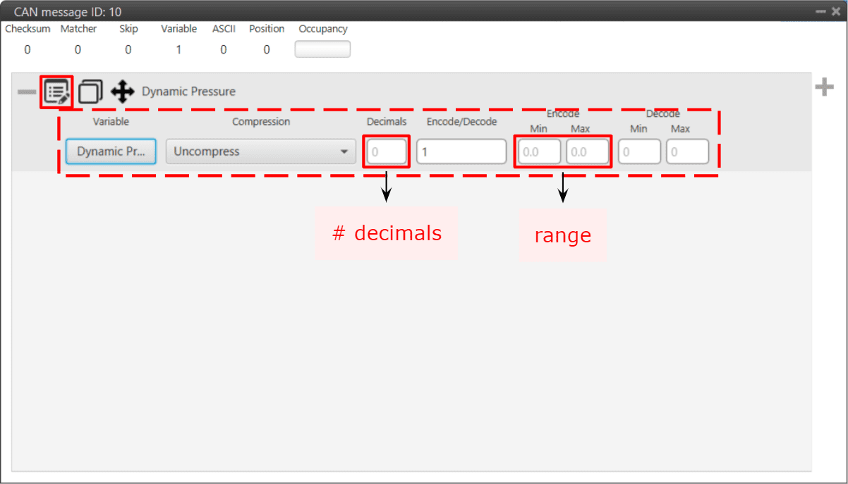
Variable configuration - CAN Custom Message
The following parameters are configurable:
Variable: Here the user select the desired system variable.
Compression: The first step is to configure which kind of compression will be used for this variable:
Uncompress: The variable is taken in its full length, with no value modification.
Uncompress - 64 bits: Uncompress from 32 to 64 bits (TX). In RX, uncompress from 64 to 32 bits.
Warning
Be careful! This transformation implies a loss of precision in both directions.
Compress - Decimals: The variable is compressed according to the number of decimals specified and the range specified (max and min values). The resultant compression (number of bits) follows the relation \((max-min) \cdot 10^{decimals}\), which yields the encoding of the maximum value of the range (and the number of bits necessary for that). The range needs to be specified on the Encode - Min/Max field.
Compress - Bits Signed: Specify the number of bits to be compressed to (negative values accepted). It is necessary that the user configures Encode/Decode options.
Compress - Bits Unsigned: Specify the number of bits to be compressed to (no negative values accepted). It is necessary that the user configures Encode/Decode options.
Encode/Decode: These values are used to apply a scaling factor after the transformation from binary to decimal value, or before the transformation from decimal to binary value.
Note
If no compression is desired, the same values must be set in min/max Encode and min/max Decode. For example, Encode min=0 / max=1 and Decode min=0 / max=1.
In the example shown below, a real user variable (32 bits) is being used to receive data from an external device. This data corresponds to the heading angle of the aircraft (which goes from 0 to 359 degrees). The device is sending this information in a 16-bit data frame and the angle value times 100 (hence why the Decode section goes from 0 to 35900). This needs to be saved in 1x PDI Builder in the user variable in the range 0 to 359 (Encode).
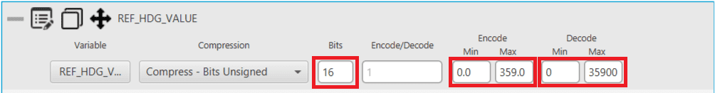
Variable configuration example
Checksum (CRC)
Sometimes, control codes are needed for preventing random errors in transmission, where a bits frame is operated and the result is sent to the receiver to check it. To do so the CheckSum option is used.
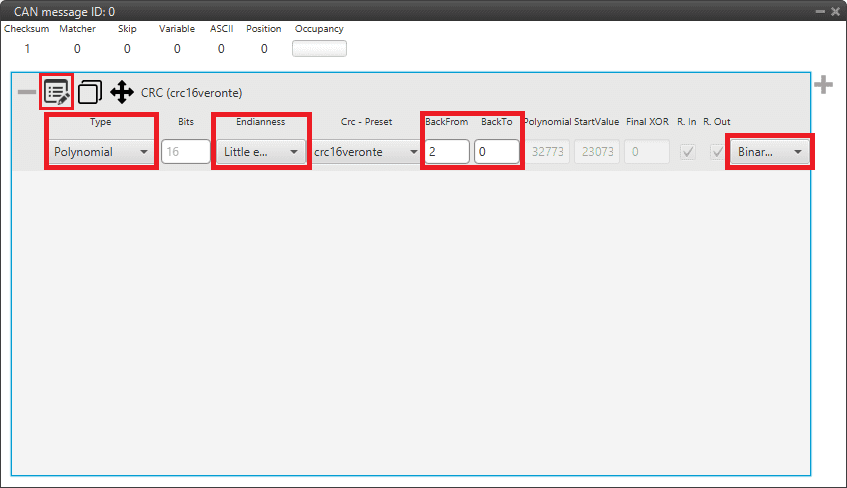
Checksum configuration - CAN Custom Message
Type: User can choose the type of CRC that will be applied.
Polynomial: Polynomial algorithm for CRC. Select from a list of predefined Embention CRC (CRC-Preset option). This is the most used type.
sum8: The CRC-8 algorithm (sum8) calculates an 8-bit checksum, which is used for error detection purposes.
Basically, it processes the sum of all bytes from a sequency, and then performs a bitwise division by 255 to retrieve the CRC result code.
sumMod: The CRC module (sumMod) is a process to calculate a checksum, which is used for error detection purposes.
It processes the sum of all bytes from a sequency, and uses a euclidian division by the module parameter to obtain the CRC result code.
Mavlink: Embention has implemented the Mavlink checksum, used only for Mavlink protocol communications.
8-bit sagetech checksum: It is an owned checksum algorithm from Sagetech, that is used by Sagetech devices for error detection purposes. It is based on Fletcher checksum.
The following parameters must be set independently of the type of checksum selected:
Endianness: The endianness of the message must be configured, which indicates how the bytes that it contains are sent/read:
Big endian: Set the value from left to right.
Little endian: Set the value from right to left.
Mixed endian: Some devices use this format. If users need to configure it, please contact the support team (create a ticket in the customer’s Joint Collaboration Framework; for more information, see Tickets section of the JCF manual).
Back From: Indicates that the CRC will be computed from the indicated byte (inclusive).
Back To: Indicates that the CRC will be computed to the indicated byte (exclusive).
Explanation
Byte 0 it is referred to the first byte of the Checksum block.
The range of calculation of the CRC is defined by the ‘Back to’ and ‘Back from’ parameters. They define, respectively, a number of bytes as an offset from the position of the CRC.
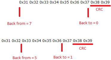
Back to/Back from explanation
Drop-down menu: User can choose the mode in which the CRC will be output:
Binary mode
ASCII as hexadeciaml values
ASCII as deciaml values
The specific parameters for each checksum type, will be described below:
Polynomial type
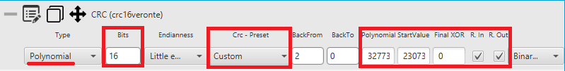
Checksum configuration - Polynomial example
In addition to the ‘general’ parameters described above, one further parameter must be configured for this type of CRC:
CRC - Preset: List of predefined Embention CRC, where fields nº Bits, Polynomial, Start Value, Final XOR, Reflect In and Out are defined.
The last option is Custom, where all the above mentioned fields can be defined by the user. Check Polynomial CRC online for more information.
Bits: This defines the width of the result CRC value (n bits).
Polynomial: Used generator polynomial value.
Start Value: The value used to initialize the CRC value / register.
Final XOR: The Final XOR value is xored to the final CRC value before being returned. This is done after the ‘Result Output’ step. Obviously a Final XOR value of 0 has no impact.
Reflected Input: If this is enabled, each input byte is reflected before being used in the calculation. Reflected means that the bits of the input byte are used in reverse order. So this also means that bit 0 is treated as the most significant bit and bit 7 as least significant.
Reflected Output: If this is enabled, the final CRC value is reflected before being returned. The reflection is done over the whole CRC value, so e.g. a CRC-32 value is reflected over all 32 bits.
sum8 type
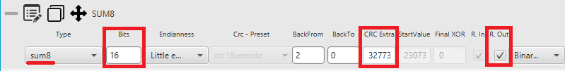
Checksum configuration - sum8 example
In addition to the ‘general’ parameters described above, 3 further parameters must be configured for this type of CRC:
Bits: This defines the width of the result CRC value (n bits).
CRC Extra: Extra CRC added at the end of the message, it will be required by the communication protocol used.
Reflected Output: If this is enabled, the final CRC value is reflected before being returned. The reflection is done over the whole CRC value, so e.g. a CRC-32 value is reflected over all 32 bits.
sumMod type
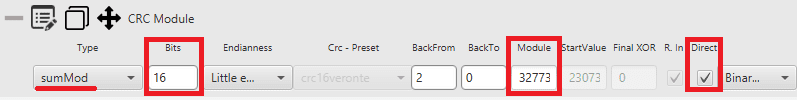
Checksum configuration - sumMod example
In addition to the ‘general’ parameters described above, 3 further parameters must be configured for this type of CRC:
Bits: This defines the width of the result CRC value (n bits).
Module: This value is the dividend of the operation carried out.
Direct:
If enable, sumMod retrieves the result code directly from the remainder of the division.
The mathical operation done is: \(CRC \, \% \, module\).
If disable, sumMod keeps the subtraction of the remainder of the division.
The mathical operation done is: \(module - (CRC \, \% \, module)\).
Mavlink type
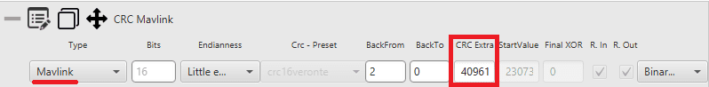
Checksum configuration - Mavlink example
In addition to the ‘general’ parameters described above, one further parameter must be configured for this type of CRC:
CRC Extra: Extra CRC added at the end of the message, it will be required by the Mavlink protocol.
8-bit sagetech checksum
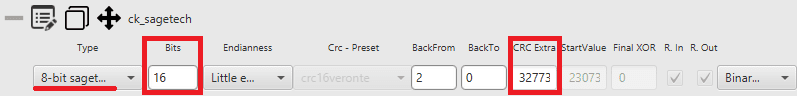
Checksum configuration - 8-bit sagetech checksum example
In addition to the ‘general’ parameters described above, 2 further parameters must be configured for this type of CRC:
Bits: This defines the width of the result CRC value (n bits).
CRC Extra: Extra CRC added at the end of the message, it will be required by the communication protocol used.
Matcher
This option is used to send a constant value through the bus in TX or wait for a particular value in RX.
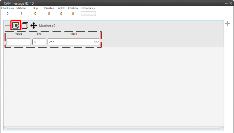
Matcher configuration - CAN Custom Message
Value: Sent/received value for the nº of bits defined below.
Bits: Number of bits in which the matcher is performed.
Mask: It is automatically set when the nº of bits is assigned.
For example, a matcher of 8 bits with a value of 9 will be reading/sending: \(0000 1001\).
Skip
This option is used to discard a certain number of bits from the message (the maximum number of bits that can be skipped with a single “Skip” are 32).
This tool can be used when there are variables incoming that are from no interest for the user, not loading unnecessary information into the system.
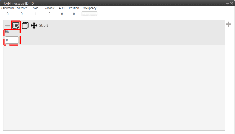
Skip configuration - CAN Custom Message
Parse ASCII
Parsing ASCII is used when the protocol required is of this kind.
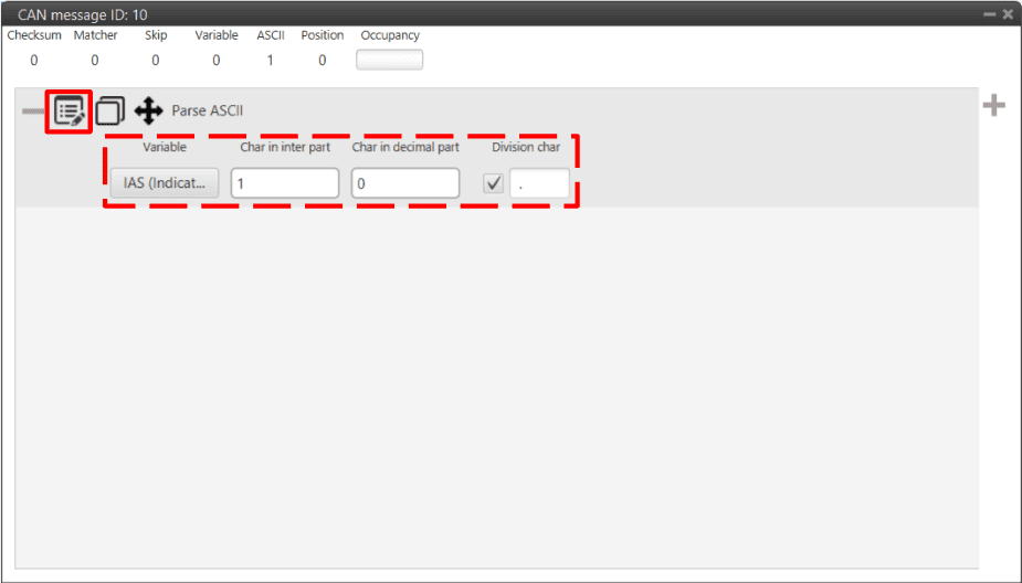
Parse ASCII configuration - CAN Custom Message
ASCII protocol is used for transforming a character array into decimal values. For such task, the user needs to define the following parameters:
Variable:
If used as TX, this variable is where the ASCII will be saved (“uncompress”).
If used as RX, this is the read variable to be tranformed into ASCII (“compress”).
Char in inter part: The number of characters in the integer part.
Char in decimal part: The number of characters in the decimal part.
Division char: This is the division character (’.’, ‘,’, etc.)
Position
Position is used to input/output a data set with a particular format. When created, the user can only choose from Features variables.
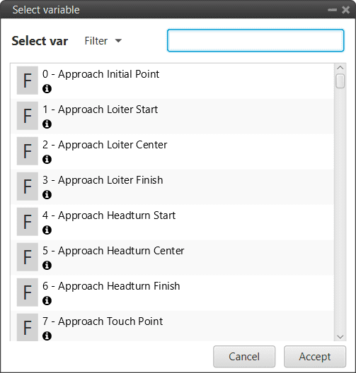
Position variables
The window display below is the configurable menu. The information stored is the WGS84 coordinates in the following order: Latitude, Longitude and Height. All of them are stored with double precision.
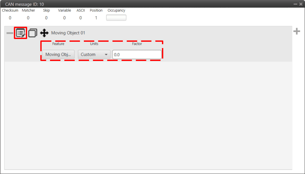
Position configuration - CAN Custom Message
Feature: User can select from Features variables.
Units: Units available are Radians, Degrees, Gradians and Custom.
Factor: As radians are the unit that 1x PDI Builder works with, if another unit is selected, the conversion factor between this unit and radians is automatically calculated.