Servos blocks
Actuator
Actuator block controls the transformation of the action to the servo value.
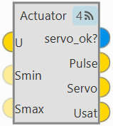
Actuator block
Inputs
 U: Control actions (U) before servo saturation. (Optional) Smin: Vector of minimum values allowed for the servos. (Optional) Smax: Vector of maximum values allowed for the servos.
Outputs
 servo_ok?: Output BIT vector that indicates the servos that had to be trimmed to prevent saturation. Pulse: PWM pulse for servos. Servo: Servo value. Usat: Control actions (U) after servo saturation.
Configuration menu:

Actuator block configuration
The servo configuration is divided into 3 different menus: Physical, Saturation and Matrices.
Physical: This tab allows the actuators physical configuration.
Warning
The calibration of all connected actuators is performed in the 1x PDI Calibration software.
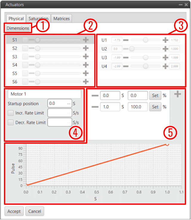
Actuator block configuration - Physical
Dimensions: Set the number of servos and control outputs.
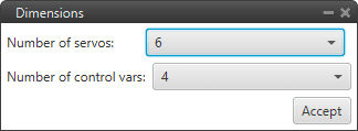
Actuator block configuration - Physical dimensions
Note
Veronte Autopilot 1x allows up to 32 actuators to be configured at the same time.
Servos (actuators): This menu contains the servos of the platform.
Control Signals: This menu contains the variables representing the control signals/outputs \(U\) generated by the system.
The mapping of the controls to servo positions is indicated within the SU matrix, which is set in the Matrices tab.
Servo parameters:
Actuator Output variable: If the Actuator output variable has been renamed, it will be renamed here as well.
Startup position (S): Sets the initial values of the actuators.
Increasing/Decreasing Rate Limit (S/s): Sets a rate limit for increasing/decreasing motions of the servo.
Servo Position - PWM: This option is used to set the mapping of the \(S\) servo position to the PWM signal. In this example, 1 \(S\) position corresponds to a 100 % pulse to be sent to the corresponding servo (Motor 1).
The mapping is expressed through the graph, where the user can enter as many points as desired.
Saturation: In this menu, the user can configure the behaviour of the platform when one or more of its actuators is/are in saturation state.

Actuator block configuration - Saturation
The three available options are:
Inactive: The system does not respond to saturation.
Linear: The system affects all the actuators in the same way if saturation is reached.
Standard: The system affects only the selected actuators if saturation is reached at any actuator. It can be chosen from 1 to all of them (which will be linear action).

Actuator block configuration - Saturation Standard
Clicking the Advanced checkbox generates a vector that includes all control outputs, allowing proportional control over the system when saturation occurs.
This tool is configured to allow the user to have more extensive control over this feature if required.
Matrices:
\(SU\) and \(US\) are 2 matrices (inverse of one another, respectively) which contain the relationship between actuator outputs \(S\) and control outputs \(U\), i.e. the influence of each control channel on each actuator output. The option of having a configurable SU matrix allows Veronte Autopilots 1x to control any type of vehicle, independently of how its control surfaces/devices are set and adjusted.
\(U\) is a vector which contains the control outputs of the platform, e.g. pitch, roll, yaw, throttle, etc. The values of \(U\) do not represent a physical variable. They are instead fictitious variables which are used in the control algorithm. What is actually applied to the system are the actuators movements, i.e. the PWM signals sent to the servos, which are mapped in the \(S\) vector.
The relation between \(S\) and \(U\) is essential for the right attitude control of the platform.

Actuator block configuration - Matrices
Normally, the SU matrix is defined instead of the US matrix because it is more intuitive, the US is calculated automatically.
To define it, click Edit and the following pop-up window will open with the matrix. Control outputs \(U\) are placed on the columns and actutator outputs \(S\) on the rows. Clicking on the ‘+’ sign allows the user to add a new \(U\) or \(S\), by adding a new column, a row will appear and vice versa.
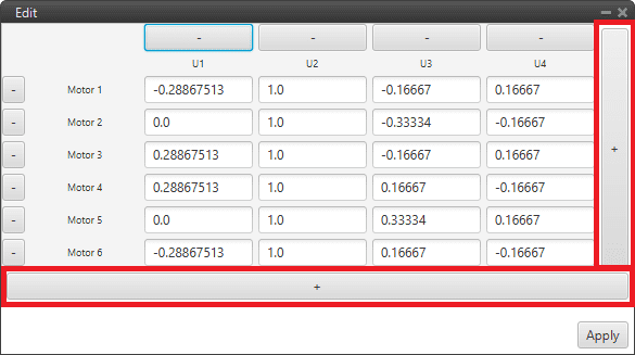
Actuator block configuration - SU matrix
In addition, an allocation matrix is available to help the user configure these matrices for a multi-rotor.
Warning
Regarding the selection of the parameters of \(SU\) matrix, the order of magnitude of the parameters should be respected at least for every row, i.e. every control channel, as long as there are no coupled control channels \(U\).
Good practice recommendations
Unitary values are recommended. Doing so, \(U\) will be equal to \(S\). And if \(S\) has been defined according to a physical value – e.g. deflected angle, then control outputs can be easier to understand.
The order of magnitude and the value of the \(SU\) parameters will not influence control algorithm calculations. But it will affect the control parameters, i.e. the control gains.
It is recommended to keep the same order of magnitude for the whole matrix. That will allow an easier set up of a scaled version of the platform. Keeping the same \(SU\) and knowing the scaling factor, then the new control gains should be the old ones multiplied by that scaling factor. This practice can also be useful for transition to similar platforms.
The \(SU\) matrix and \(S\) vector should be defined accordingly in order to follow the sign convention for aerial navigation, a positive roll lowers the right wing, a positive pitch moves the nose up and a positive yaw moves the nose the right.
An example of the use of this block is given below:
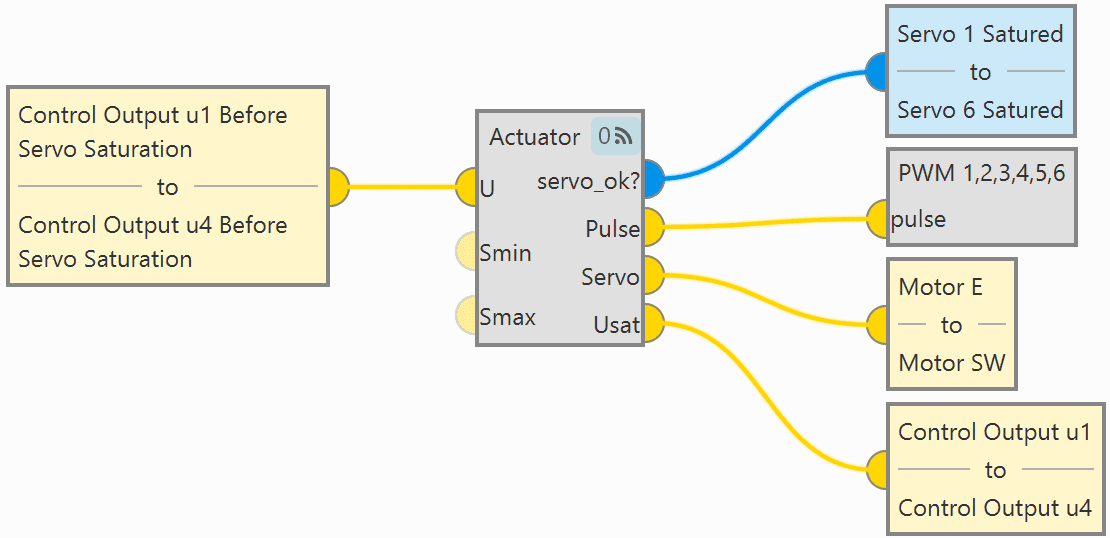
Actuator block - Example of use
Arc Trim
Arcade stick trim block is used to set the zero-stick position for the Arcade Mode.
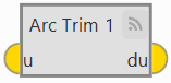
Arc Trim block
The Stick input variable that enters the navigation algorithm is called ‘Stick input \(d\)’, which is the one obtained from the Arc Trim block.
It is calculated as \(D=U-U_{0}\), where \(U_{0}\) is the arcade trim.
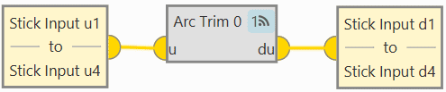
Arc Trim block - Example of use
Input
u: Input stick vector to trim.Output
du: Trimmed stick vector.Configuration menu:

Arc Trim block configuration
The values of the trim vector \(U_0\) can be entered manually in the configuration menu (as shown in the figure above) or by creating an automation that autocompletes these values with the stick position. For the latter case, the configuration menu should be with all trim values to 0.
For more information on this automation, see Arcade trim automation section.
Warning
The Arcade mode has to be trimmed before flight. If not trimmed, the zero level will be different from the desired one.
PWM
PWM block applies the input vector to the configured PWM outputs.

PWM block
Input
pulse: Input vector of pulses to apply.Configuration menu:
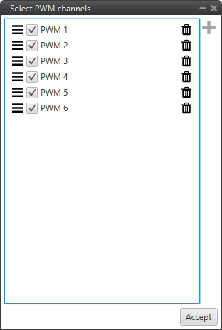
PWM block configuration
 : Users must enter the PWM variables to be configured.
 : PWMs variables can be sorted as desired by simply dragging and dropping them.
Check the variable to enable commands to this PWM.
 : Deletes the PWM.
A PWM servo configuration can be found in PWM - Servos of the Integration examples section.