External sensors
Veronte Autopilot 1x can be integrated with any external sensor that shares the communication interface.
External sensors can be configured to be considered as part of the sensors fusion.
LM335 with Autopilot 4x
Once LM335 sensor is wired and connected to Autopilot 1x or 4x (according to LM335 - 4x User Manual), the value can be monitored in 1x PDI Builder by using the variables ADC1 to ADC5.
Note
For pin ANALOG_1 the correspondent ADC variable in 1x PDI Builder is ADC1.
Read the following steps to configure a Veronte Autopilot 1x:
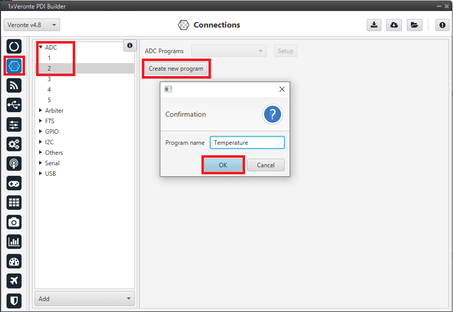
Go to Connections menu \(\rightarrow\) ADC 2 section (This is only an example, the user must select the ADC pin where the signal is connected).
Click on ‘Create new program’:
Create ADC program
Go to Block Programs menu \(\rightarrow\) Launch Editor.
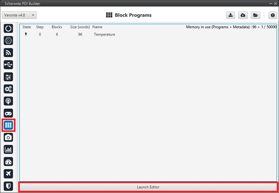
Configure the following operation (for more information about blocks, read Block Programs):
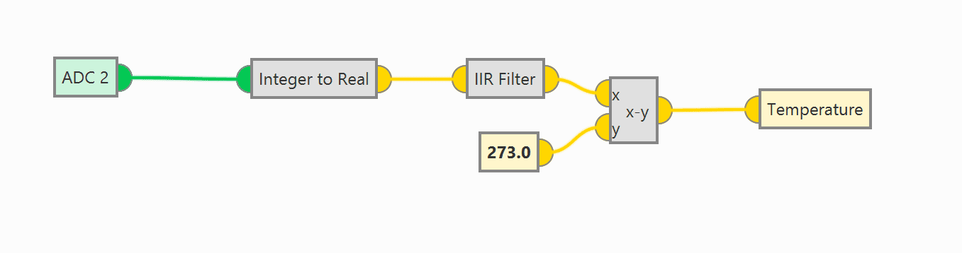
LM335 sensor operation
Note
The Temperature variable is an User Variable which has been renamed.
The equation to obtain temperature (in ºC) from voltage is: \(T = Vout · 100 - 273\). Nonetheless, in the blocks program, the input signal is not multiplied by 100, since ADC expresses the voltage in hundredths.
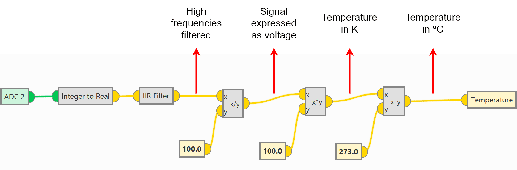
LM335 sensor operation detailed
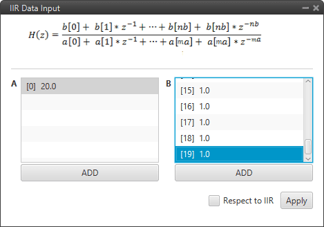
The IIR Filter block requires the following configuration, where the column B has 20 coefficients (from 0 to 19) with value 1.
Click on Apply to save the changes.
IIR Filter block configuration
Save the configuation in the Autopilot 1x.
After implementing the operation, the variable Temperature (User variable renamed) will represent the temperature (in °C) measured by the LM335 sensor.
Tip
With Veronte Ops it is possible to check that the sensor is working correctly.

Temperature value in Veronte Ops
Magnetometer Honeywell HMR2300
RS-232
Magnetometer Honeywell HMR2300 can be connected via RS-232 (serial interface) in accordance with the manufacturer’s specifications and following the Hardware installation - Electrical section of the 1x user manual.
The following steps explain how to configure Veronte Autopilot 1x to integrate this external magnetometer:
Go to Connections menu \(\rightarrow\) Serial section \(\rightarrow\) 232 tab.
Configure the serial communication settings:
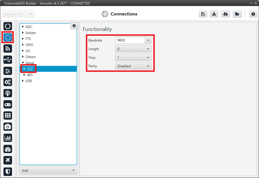
RS-232 connection configuration
Go to Block Programs menu.
Create a program to make the necessary connection to the sensor blocks.
Usually the user has a Navigation program where the sensor blocks are implemented.
Configure the Magnetometer sensor block selecting External HMR2300.
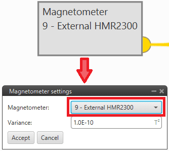
Magnetometer sensor block configuration
For more information on this block, see Magnetometer sensor of Block Programs section.
Go to Sensors menu \(\rightarrow\) Magnetometer section \(\rightarrow\) External HMR2300 tab.
Set the rotation matrix according to the sensor installation by clicking on Edit Rotation Matrix:
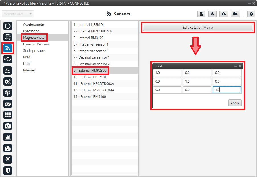
External HMR2300 magnetometer - Rotation matrix
Go to Input/Output menu \(\rightarrow\) I/O Setup section.
Bidirectionally connect the RS232 Producer to the External HMR2300 magnetometer Consumer:
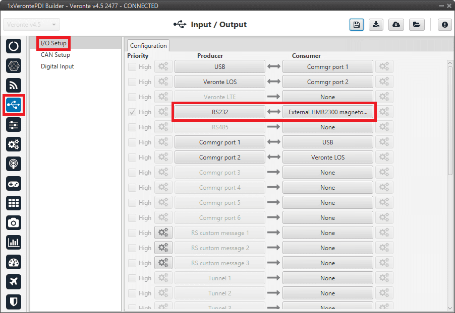
RS232 \(\leftrightarrow\) External HMR2300 magnetometer
Then, the External HMR2300 magnetometer Producer should be automatically connected to the RS232 Consumer:
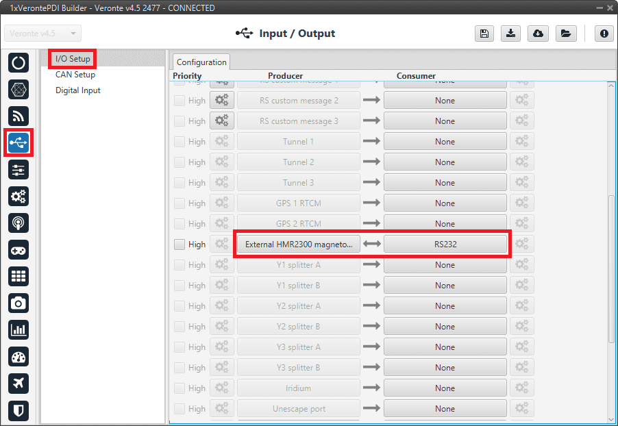
External HMR2300 magnetometer \(\leftrightarrow\) RS232
For more information on the Magnetometer Honeywell HMR2300, check out the datasheet: Smart Digital Magnetometer HMR2300.
RS-485
Magnetometer Honeywell HMR2300 can be connected via RS-485 (serial interface) in accordance with the manufacturer’s specifications and following the Hardware installation - Electrical section of the 1x user manual.
Follow the next steps to stablish a correctly communication between Honeywell HMR2300 magnetometer and Veronte Autopilot 1x via RS-485:
Connect the Honeywell HMR2300 magnetometer via USB to the PC (with a USB-RS485 conversor).
The configuration to establish communication must be:
In binary mode
With continuous fowarding
ID = 00
To configure the magnetometer in this way, the following commands must be sent to it:
*99Q: This command reads the default values, including the device ID.*00WE: This enables writing.*ddID=00: Changes the ID to 00, where dd is the device ID obtained with the first command.*00WE: Enables writing.*00B: Binary mode.*00C: Continuous send mode.*00WE: Enables writing.*00SP: Finally, this command saves the configuration in EEPROM.
Autopilot can now be configured to communicate via RS485 with the Honeywell HMR2300 magnetometer.
The configuration to be carried out is very similar to that described above for communication with the magnetometer via RS-232:
Instead of configuring the 232 connection, the 485 connection is configured.
And, the bidirectional connection must be made between the RS485 port and External HMR2300 magnetometer and not with the RS232 port.
For more information on the Magnetometer Honeywell HMR2300, check out the datasheet: Smart Digital Magnetometer HMR2300.
MEX as Magnetometer Honeywell HMR2300
MEX can be used as an external magnetometer Honeywell HMR2300 connected to Veronte Autopilot 1x via serial interface, RS-232 or RS-485. For this serial connection, check the Hardware installation - Electrical section of the 1x user manual.
The following steps explain how to configure Veronte Autopilot 1x to integrate it as an external magnetometer:
Go to Connections menu \(\rightarrow\) Serial section \(\rightarrow\) 232/485 tab.
Configure the serial communication settings:
Note
If the user connects the MEX via RS-485, configure the RS-485 port instead of RS-232.

RS-232 connection configuration
Go to Block Programs menu.
Create a program to make the necessary connection to the sensor blocks.
Usually the user has a Navigation program where the sensor blocks are implemented.
Configure the Magnetometer sensor block selecting External HMR2300.
Magnetometer sensor block configuration
For more information on this block, see Magnetometer sensor of Block Programs section.
Go to Sensors menu \(\rightarrow\) Magnetometer section \(\rightarrow\) External HMR2300 tab.
Set the rotation matrix according to the sensor installation by clicking on Edit Rotation Matrix:
External HMR2300 magnetometer - Rotation matrix
Go to Input/Output menu \(\rightarrow\) I/O Setup section.
Bidirectionally connect the RS232 Producer to the External HMR2300 magnetometer Consumer:
Note
If the user connects the MEX via RS-485, connect the RS485 Producer instead of RS232 Producer.
RS232 \(\leftrightarrow\) External HMR2300 magnetometer
Then, the External HMR2300 magnetometer Producer should be automatically connected to the RS232 Consumer:
Note
If the user connects the MEX via RS-485, the RS485 Consumer shall be connected instead of the RS232 Consumer.
External HMR2300 magnetometer \(\leftrightarrow\) RS232
OAT Sensor
Once OAT sensor is connected to 1x autopilot, the value can be monitored in 1x PDI Builder by using the variables ADC1 to ADC5.
Note
For pin ANALOG_1 the correspondent ADC variable in 1x PDI Builder is ADC1.
Read the following steps to configure it:
Go to Connections menu \(\rightarrow\) ADC 1 section.
Click on ‘Create new program’:
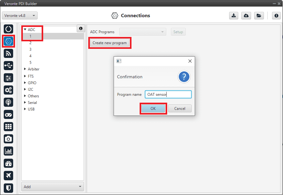
Create ADC program
Go to Block programs menu.
Configure the following operation (for more information about blocks, see Block Programs):
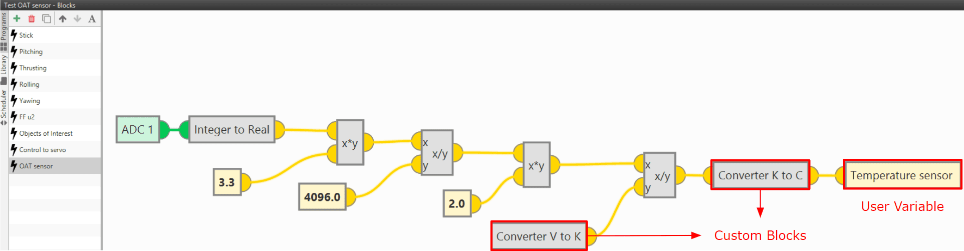
OAT sensor operation
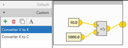
Custom block: Converter from V to K
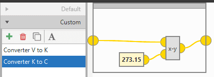
Custom block: Converter from K to °C
After implementing the operation, the variable Temperature sensor will represent the temperature (in °C) measured by the OAT sensor.
Note
If the temperature is needed in other units, the only thing necessary would be to modify the Custom block Converter K to C, or simply remove it.
Note
As 4x autopilot can read up to 36 V per each ADC, the \(3.3\) value of the ADC program must be changed to \(36\) if applicable.
Vectornav VN-300
Vectornav VN-300 is an external IMU that can be connected via RS-232 (serial interface) to Veronte Autopilot 1x.
The following steps explain how to configure Veronte Autopilot 1x to integrate this external IMU:
Go to Connections menu \(\rightarrow\) Serial section \(\rightarrow\) 232 tab.
Configure the serial communication settings:
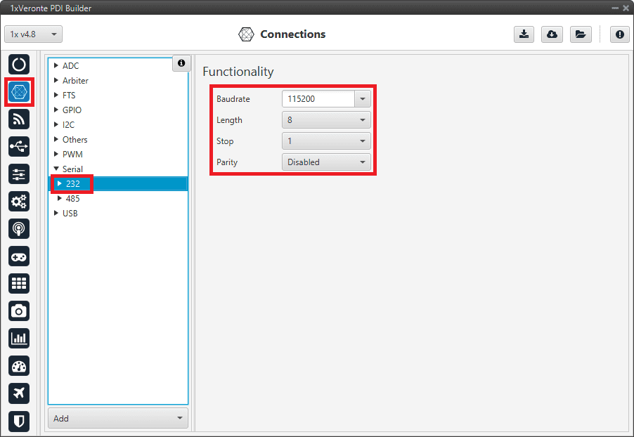
RS-232 connection configuration
Go to Input/Output menu \(\rightarrow\) I/O Setup section.
Connect the RS232 Producer to the Vectornav VN-300 Consumer:
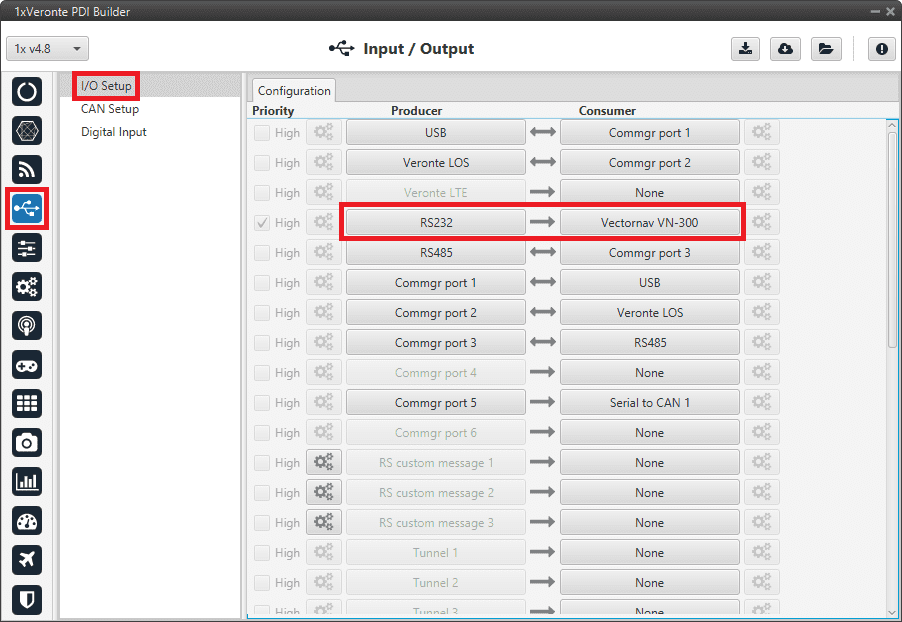
RS232 \(\rightarrow\) Vectornav VN-300
Go to Block Programs menu.
Create a program to configure the Vectornav VN-300 as the type of navigation.
Usually the user has a Navigation program where the blocks that are related to the navegation are implemented.
Configure the Navigation block selecting Vectornav VN-300.
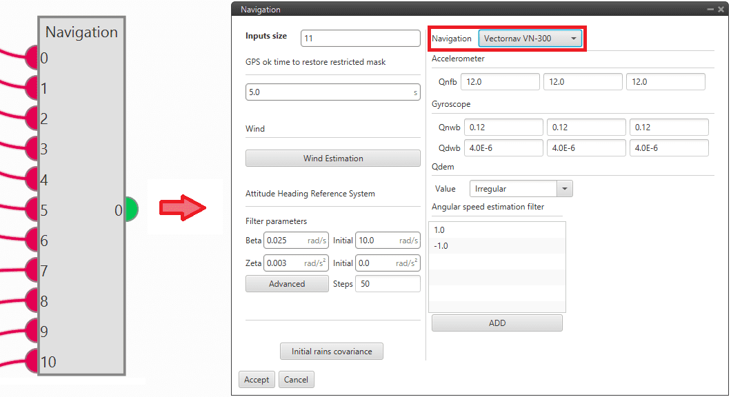
Navigation sensor block configuration
For more information on this block, see Navigation of Block Programs section.