Hardware Installation
Mechanical
Veronte Autopilot 1x is manufactured using an anodized aluminium enclosure with enhanced EMI shielding and IP protection. A high reliability connector is also provided in this version. The total weight of W/O DAA variant is 198 g and it is 210 g for versions with Remote ID or ADS-B.
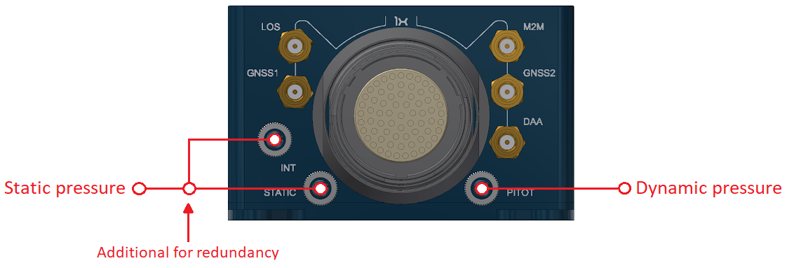
Pressure lines
Veronte Autopilot 1x has three pressure input lines, two for static pressure to determine the absolute pressure and one for pitot in order to determine the dynamic pressure.
For the fittings it is recommended to use a polyurethane tube of 2.5 mm inner diameter and 4 mm outer diameter.
-
Pressure Intake
- Pressure intakes must be located in order to prevent clogging.
- Never install pressure intakes on the propeller flow.
- Design pressure tubing path in order to avoid tube constriction.
-
Static Pressure
- It is not recommended to use inside fuselage pressure if it is not properly vented.
-
Pitot Tube
- Pitot tube must be installed facing the airflow.
- It is recommended to install it near the aircraft's x axis in order to avoid false measures during manoeuvres.
- For low-speed aircraft it is recommended at least 6.3mm tubes to prevent any rain obstruction.
Note
In case of not using an input air connector, it is recommended to remove its corresponding nut. Vibrations may move and damage intake connectors with a nut that is not fixed with a tube.
Location
The location of Veronte Autopilot 1x has no restrictions. You only need to configure its relative position with respect to the centre of mass of the aircraft and the GNSS antenna. The configuration of the location of Veronte Autopilot 1x can be easily configured using 1x PDI Builder.
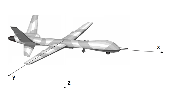
Orientation
The orientation of Veronte Autopilot 1x has no restrictions either. You only need to configure axes with respect to the aircraft body axes by means of a rotation matrix or a set of correspondences between axes. The configuration of the orientation can be easily configured using 1x PDI Builder.
Axes are printed on the Autopilot 1x box. Aircraft coordinates are defined by the standard aeronautical conventions (see image below).
Vibration Isolation
Although Veronte Autopilot 1x rejects noise and high-frequency vibration modes with electronic filters, there may be situations where external isolation is needed.
Autopilot 1x can be mounted in different ways in order to reject the airframe vibration, but it is recommend to use the Damping System designed for that porpuse. It covers a wide frequency range of different aircraft types.
Note
The user should take into account that wiring should be loose enough so that vibrations are not transmitted to Autopilot 1x.
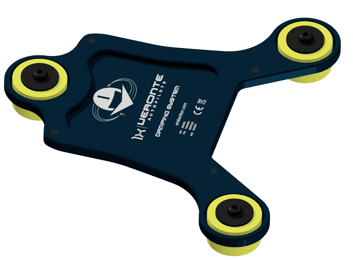
Damping System
Embention offers the Damping System as a solution to isolate Veronte Autopilot 1x from vibrations.
Important
Only effective with Autopilot 1x in horizontal position.
This damping system weighs 60 g.
Warning
The Damping System is designed for hardware version 4.8 of Autopilot 1x.
Dimensions
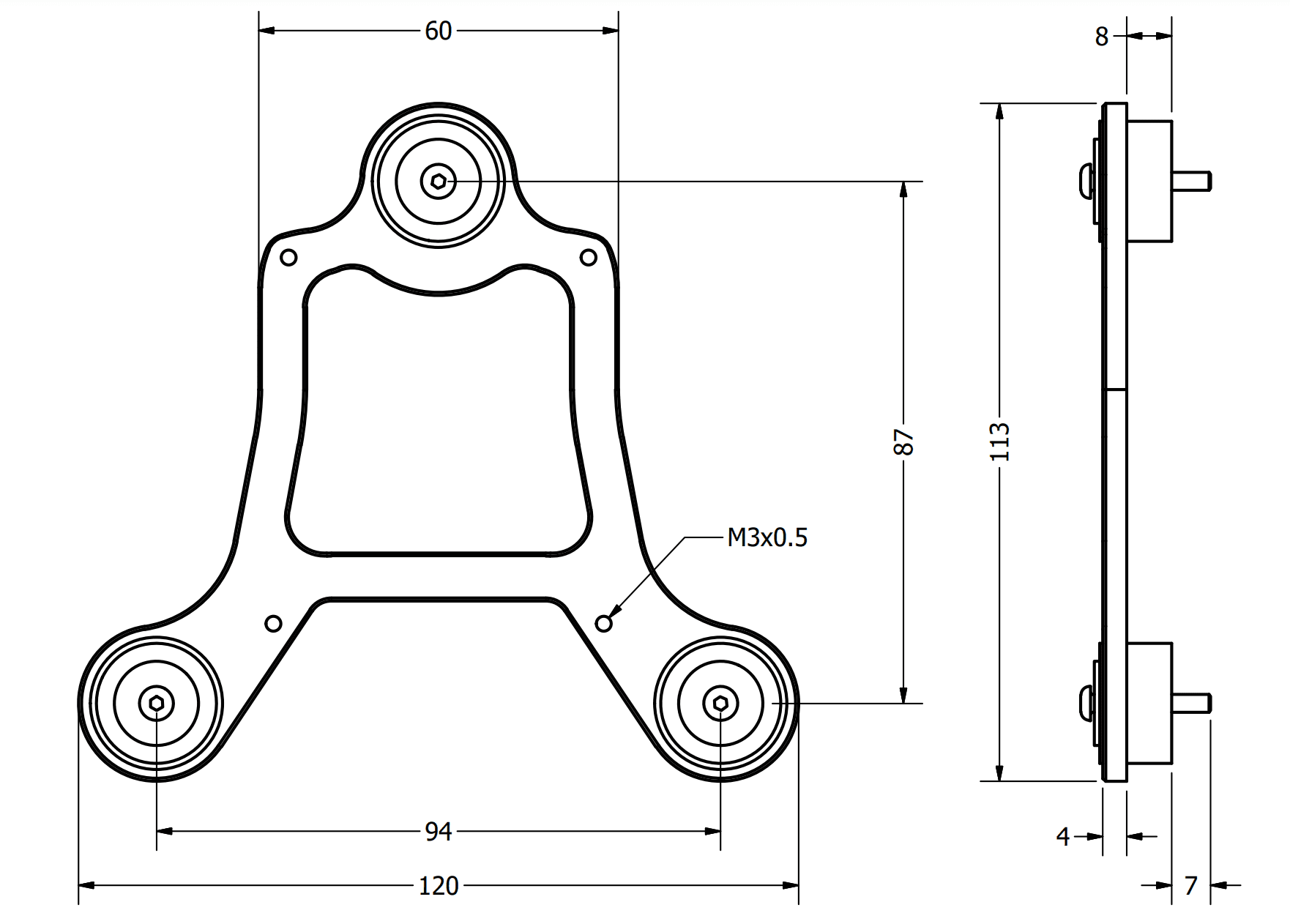
Assembly steps
To assembly the Damping System into a vehicle with an Autopilot 1x, read the following steps.
-
Remove the three nuts located under the platform.
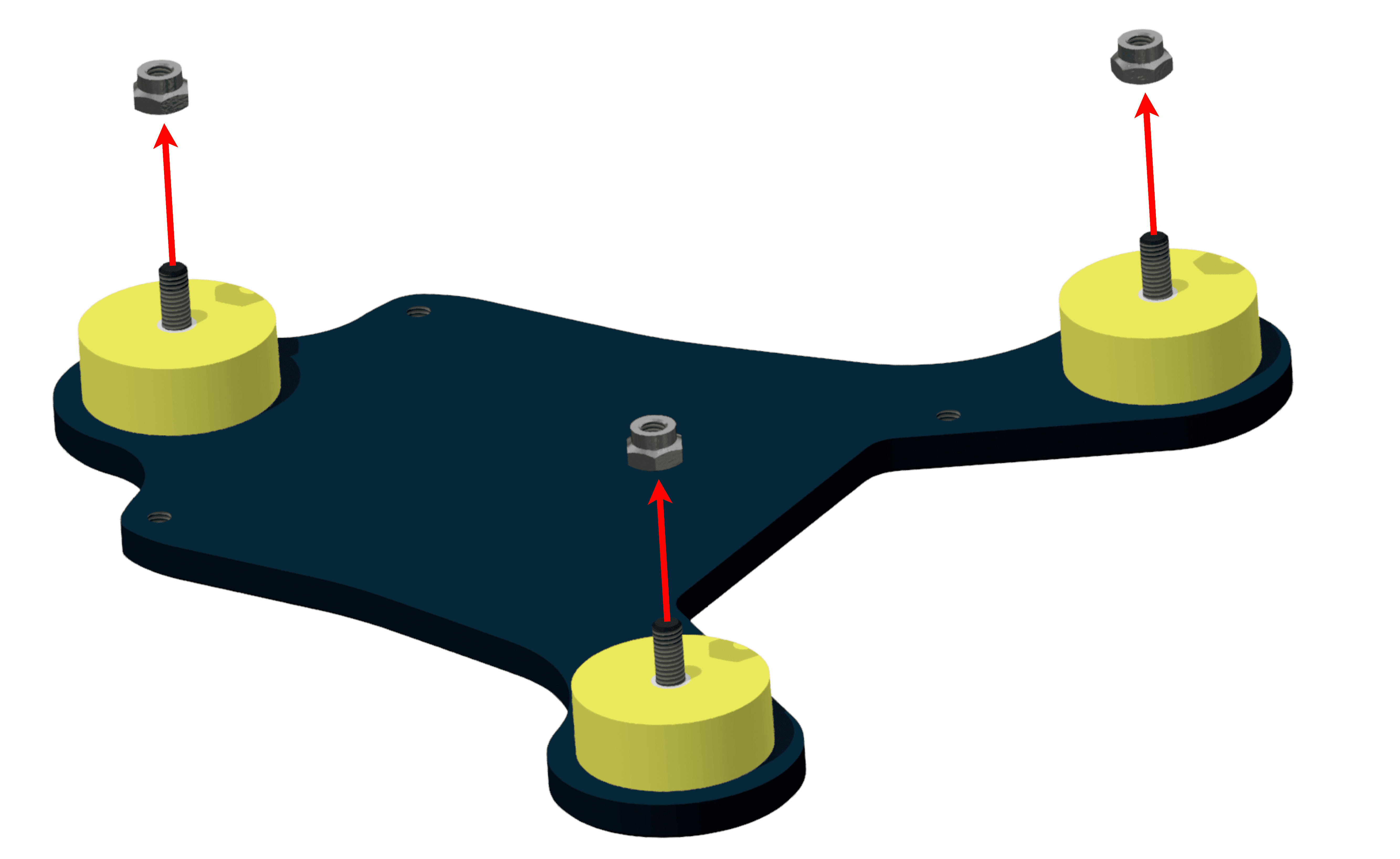
Step 1 -
Screw the platform on the aircraft frame. The included screws have M3.
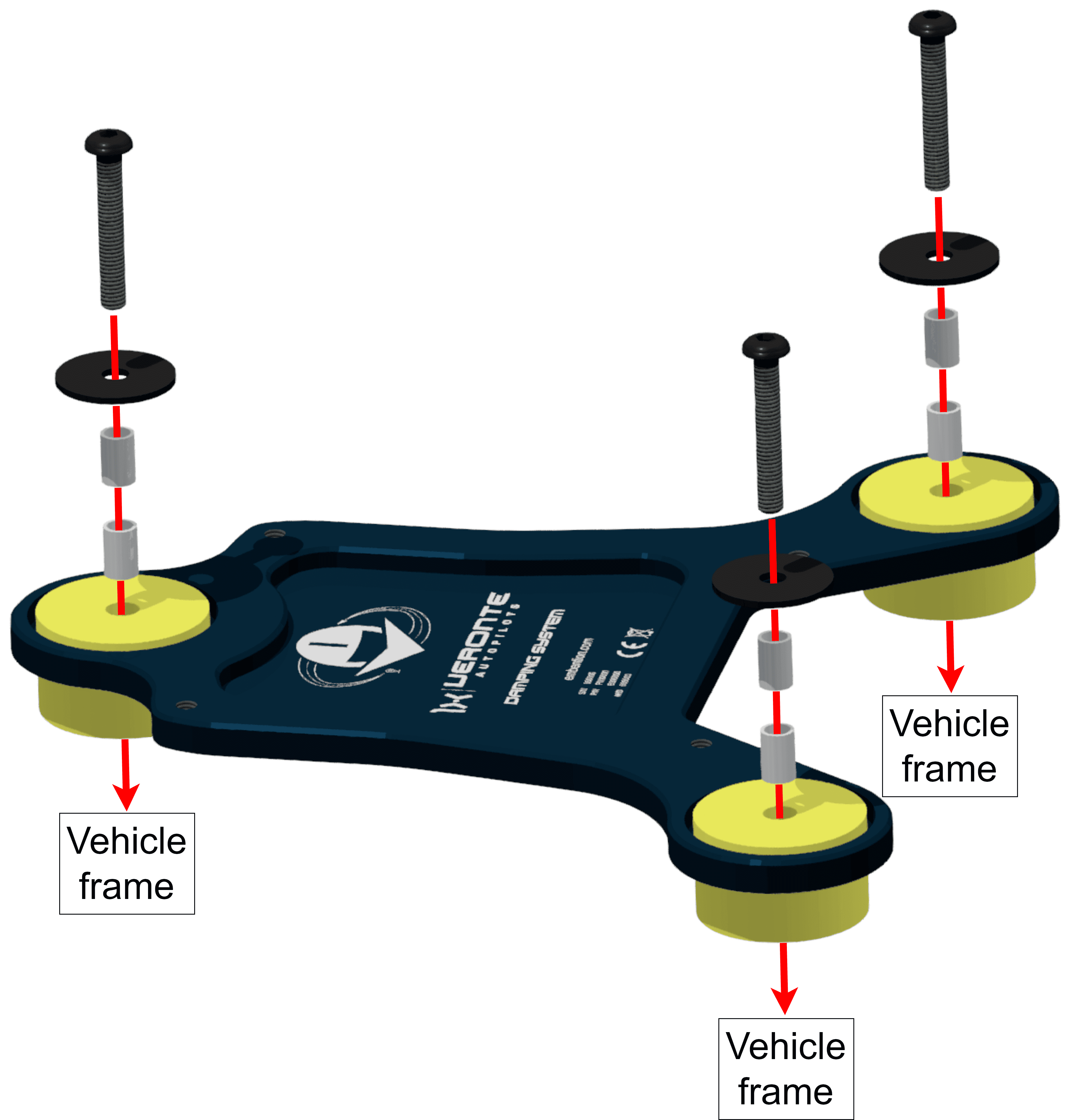
Step 2 -
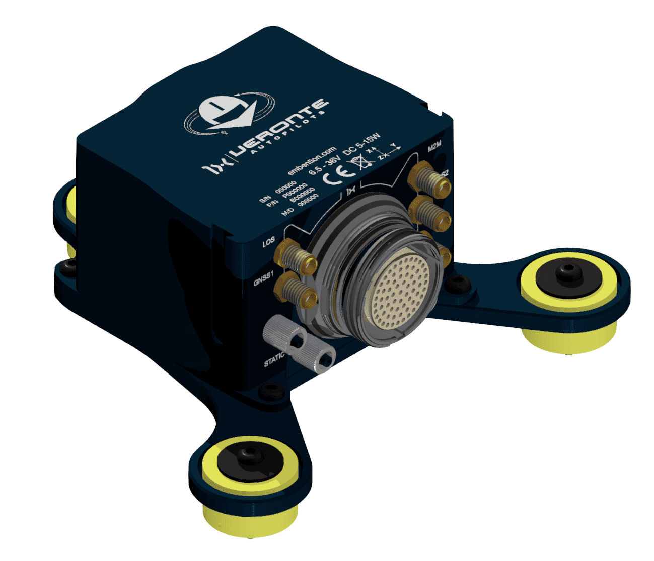
Screw the Autopilot 1x on the Damping system.
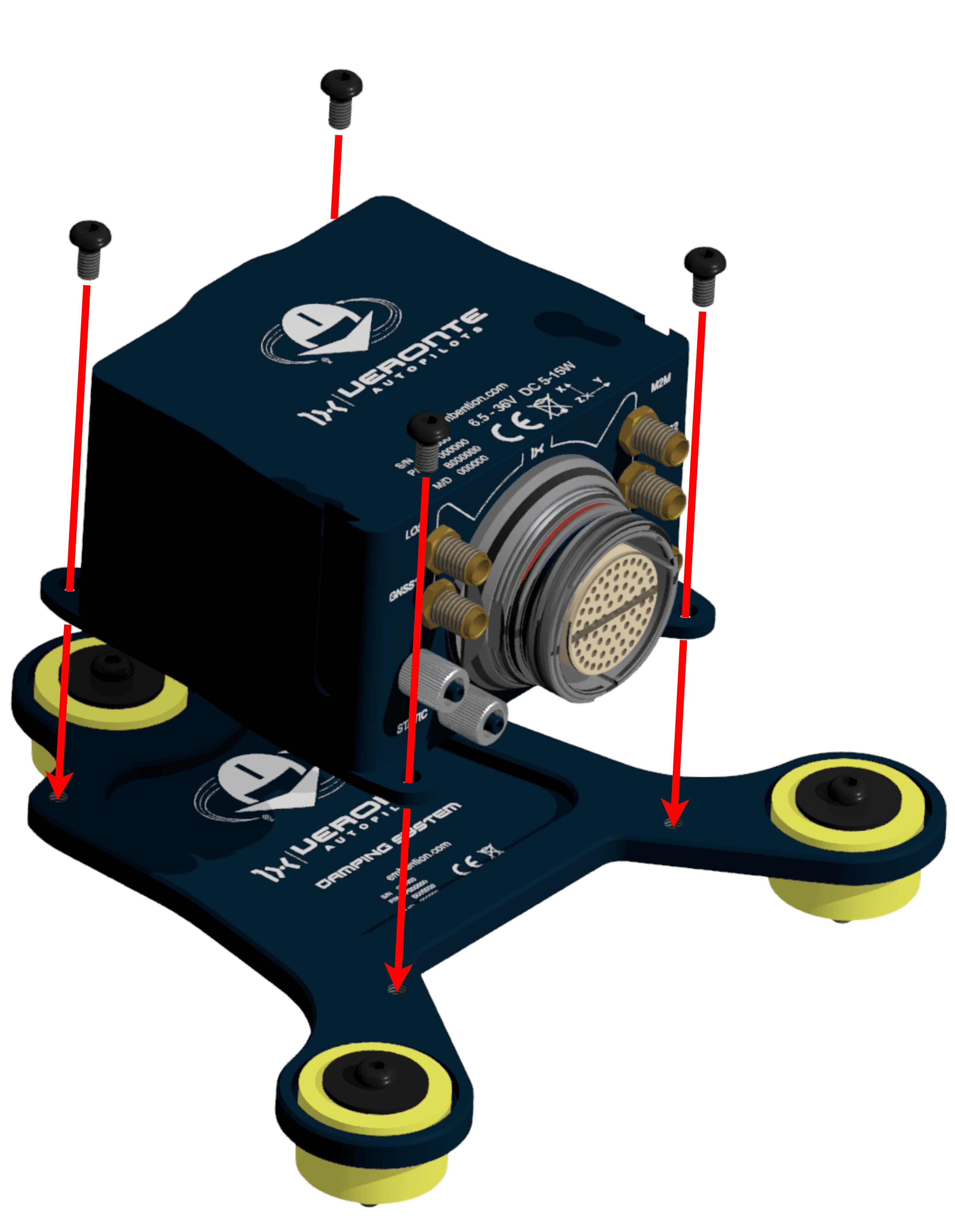
Step 3
Vibration analysis
-
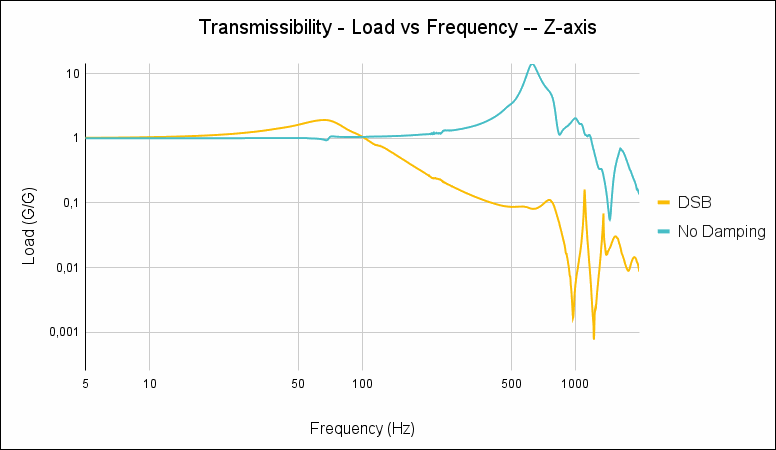
Transmissibility (Z-axis)
Transmissibility graph, analysis of vibrations received by Autopilot 1x, with and without Damping System:
Transmissibility graph -
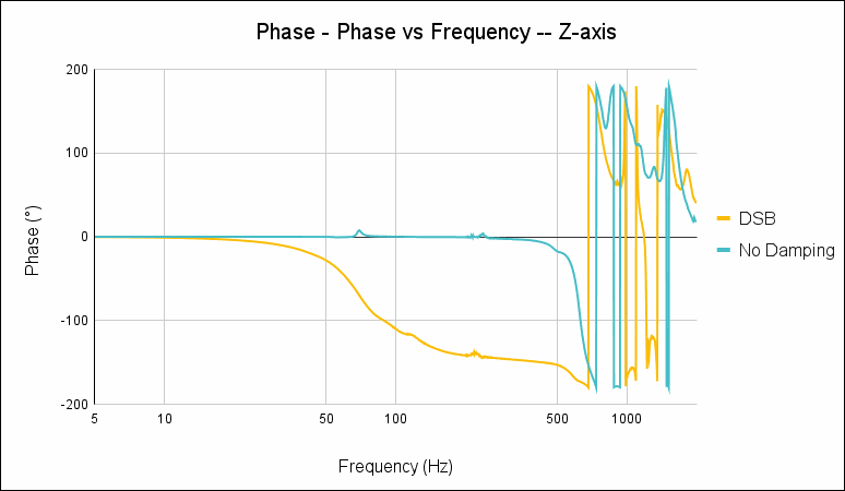
Phase (Z-axis)
Phase graph, analysis of whether vibrations measured by Autopilot 1x are in phase or not, with and without Damping System:
Phase graph
Antenna Integration
The system uses different kinds of antennas to operate that must be installed on the airframe. Here you can find some advice for obtaining the best performance and for avoiding antenna interferences.
-
Antenna Installation
- Maximize separation between antennas as much as possible.
- Keep them far away from alternators or other interference generators.
- Always isolate antenna ground panel from the aircraft structure.
- Make sure the antenna is securely mounted.
- Always use high-quality RF wires minimising the wire length.
- Always follow the antenna manufacturer manual.
- SSMA connections shall be tightened applying 1Nm of torque
- For all-weather aircraft, insert SSMA lightning protectors.
-
GNSS Antenna
- Antenna top side must point the sky.
- Install it on a top surface with direct sky view.
- Never place metallic / carbon parts or wires above the antenna.
- It is recommended to install it on a small ground plane.
- For all-weather aircraft, insert SSMA lightning protectors.
-
Recommended specifications for GNSS antennas
Specifications Range Antenna frequency L1 1561.098 MHz to 1602 MHz Antenna frequency L2 1207.14 MHz to 1246 MHz Amplifier gain 17 dB to 35 dB Out-of-band rejection 40 dB
Note
Higher values are preferable.
30 dB is considered the minimum acceptable value.Polarization RHCP (Right-Hand Circular Polarization) Minimum supply voltage 2.7 V to 3.3 V Maximum supply current 50 mA
Electrical
Power
Veronte Autopilot 1x can use unregulated DC (6.5V to 36V). Pins used for power and ground are the same for both Ground and Air configurations.
LiPo batteries between 2S and 8S can be used without regulation needs. Remaining battery level can be controlled by the internal voltage sensor and by configuring the voltage warnings by software.
For higher voltage installations, voltage regulators must be used. For dimensioning voltage regulators take into account that a blocked servo can activate regulator thermal protection.
Caution
Caution!! Power Veronte Autopilot 1x out of range can cause irreversible damage to the system. Please read carefully the manual before powering the system.
Autopilot 1x and servos can be powered by the same or different batteries. In case of having more than one battery on the system, a single point ground union is needed to ensure a good performance. The ground signal should be isolated from other noisy ground references (e.g. engines). If all grounds need to be connected, the connection should be made on the negative pole of the battery.
It is recommendable to use independent switches for autopilot and motor/actuators. During the system initialization, the PWM signal will be set to low level (0V), please make sure that actuators/motor connected support this behaviour before installing a single switch for the whole system.
Pinout

Warning
Check the pin number before connecting. The color code is repeated 3 times due to the amount of pins. First section (yellow) corresponds to pins 1-30, the second section (blue) to pins 31-60 and the third one (red) to pins 61-68. Pin number increases counterclockwise following the black line of the picture above.
| PIN | Signal | Type | Description | |
|---|---|---|---|---|
| 1 | I/O 0 | I/O |
Pins for PWM or digital I/O signals (0-3.3V). Protected against ESD and short circuit.
Warning Each pin withstands a maximum current of 1.65 mA. |
|
| 2 | I/O 1 | |||
| 3 | I/O 2 | |||
| 4 | I/O 3 | |||
| 5 | I/O 4 | |||
| 6 | I/O 5 | |||
| 7 | I/O 6 | |||
| 8 | I/O 7 | |||
| 9 | GND | GROUND | Ground signal for actuators 1-8. | |
| 10 | I/O 8 | I/O | Pins for PWM or digital I/O signals (0-3.3V). Protected against ESD and short circuit.
Warning Each pin withstands a maximum current of 1.65 mA. |
|
| 11 | I/O 9 | |||
| 12 | I/O 10 | |||
| 13 | I/O 11 | |||
| 14 | I/O 12 | |||
| 15 | I/O 13 | |||
| 16 | I/O 14 | |||
| 17 | I/O 15 | |||
| 18 | GND | GROUND | Ground signal for actuators 9-16. | |
| 19 | RS232 TX | Output | RS 232 Output (-13.2V to 13.2V Max, -5.4V to 5.4V Typical). Protected against ESD and short circuit. | |
| 20 | RS232 RX | Input | RS 232 Input (-25V to 25V Max, -0.6V Low and 2.4V High Threshold). Protected against ESD and short circuit. | |
| 21 | GND | GROUND | Ground signal for buses. | |
| 22 | ANALOG_3 | Input | Input 0-3.3V. Protected against ESD and short circuit. | |
| 23 | ANALOG_4 | Input | Input 0-3.3V. Protected against ESD and short circuit. | |
| 24 | GND | GROUND | Ground signal for buses. | |
| 25 | CANA_P | I/O | CANbus interface, up to 1Mbps. Protected against ESD. | |
| 26 | CANA_N | I/O | Twisted pair with a 120 ohms Zo recommended. Protected against ESD. | |
| 27 | 4XV_WD | I/O | Reserved. Do not connect. | |
| 28 | CANB_P | I/O | CANbus interface. It supports data rates up to 1 Mbps. Protected against ESD. | |
| 29 | CANB_N | I/O | Twisted pair with a 120 ohms Zo recommended. Protected against ESD. | |
| 30 | GND | GROUND | Ground signal for buses. | |
| 31 | I2C_CLK | Output | Clock line for I2C bus (0.3V to 3.3V). Protected against ESD and short circuit. | |
| 32 | I2C_DATA | I/O | Data line for I2C bus (0.3V to 3.3V). Protected against ESD and short circuit. | |
| 33 | GND | GROUND | Ground for 3.3V power supply. | |
| 34 | 3.3V | Power | 3.3V - 100mA power supply. Protected against ESD short circuit with 100mA resettable fuse. | |
| 35 | GND | GROUND | Ground for 5V power supply. | |
| 36 | 5V | Power | 5V - 100mA power supply. Protected against ESD short circuit with 100mA resettable fuse. | |
| 37 | GND | GROUND | Ground for analog signals. | |
| 38 | ANALOG_0 | Input | Analog input 0-3.3V. Protected against ESD and short circuit. | |
| 39 | ANALOG_1 | Input | Analog input 0-3.3V. Protected against ESD and short circuit. | |
| 40 | ANALOG_2 | Input | Analog input 0-3.3V. Protected against ESD and short circuit. | |
| 41 | 4XV_A | I/O | Reserved. Do not connect. | |
| 42 | FTS1_OUT | Output | Deadman signal from comicro. Protected against ESD and short circuit. | |
| 43 | FTS2_OUT | Output | !SystemOK Bit. Protected against ESD and short circuit. | |
| 44 | 4XV_B | I/O | Reserved. Do not connect. | |
| 45 | UARTA_TX | Output | Microcontroller UART. | |
| 46 | UARTA_RX | Input | Microcontroller UART. | |
| 47 | GND | GROUND | Ground signal comicro power supply. | |
| 48 | V_ARB_VCC | POWER | Veronte comicro power (6.5V to 36V). Protected against ESD and reverse polarity. | |
| 49 | FTS3_OUT_MPU | Output | MPU alive voting signal, to use with 4xVeronte. It is a Square Wave at [100,125] Hz. Protected against ESD and short circuit. | |
| 50 | OUT_RS485_P | Output | Non-inverted output from RS485 bus (-7V to 12V Max, -2.3V to 2.3V Typical). Protected against ESD and short circuit. | |
| 51 | OUT_RS485_N | Output | Inverted output from RS485 bus (-7V to 12V Max, -2.3V to 2.3V Typical). Protected against ESD and short circuit. | |
| 52 | IN_RS485_N | Input | Inverted input from RS485 bus (-7V to 12V Max, -2.3V to 2.3V Typical). Protected against ESD and short circuit. | |
| 53 | IN_RS485_P | Input | Non-inverted input from RS485 bus (-7V to 12V Max, -2.3V to 2.3V Typical). Protected against ESD and short circuit. | |
| 54 | OUT_GND | GND |
Ground for RS-485 bus.
Warning This is not a common GND pin. |
|
| 55 | EQEP_A | I/O | DIGITAL output / DIGITAL input / Encoder quadrature input A (0-3.3V). Protected against ESD and short circuit. | |
| 56 | EQEP_B | I/O |
DIGITAL output / DIGITAL input / Encoder quadrature input A (0-3.3V). Protected against ESD and short circuit.
Warning Only use it as digital I/O with Veronte units of Hardware version 4.5 or lower. |
|
| 57 | EQEP_S | I/O | DIGITAL output / DIGITAL input / Encoder quadrature input A (0-3.3V). Protected against ESD and short circuit. | |
| 58 | EQEP_I | I/O | DIGITAL output / DIGITAL input / Encoder quadrature input A (0-3.3V). Protected against ESD and short circuit. | |
| 59 | GND | GROUND | Ground for encoders. | |
| 60 | V_USB_DP | I/O | Veronte USB data line. Protected against ESD. | |
| 61 | V_USB_DN | I/O | Veronte USB data line. Protected against ESD. | |
| 62 | USB_SHIELD_GND | GROUND | USB cable shielding. | |
| 63 | FTS_OUT_MPU | Output | Abort mission voting signal 1 from MPU, to use with 4x Veronte. |
Bit Low (0 V) if mission OK. High (3.3V) if mission wants to be terminated. Both pins are protected against ESD and short circuit.
Warning Each pin withstands 2.5 A of maximum current. |
| 64 | FTS2_OUT_MPU | Output | Abort mission voting signal 2 from MPU, to use with 4x Veronte. | |
| 65 | GND | GROUND | Veronte ground input. | |
| 66 | GND | GROUND | Veronte ground input. | |
| 67 | VCC | POWER |
Veronte power supply (6.5V to 36V). Protected against ESD and reverse polarity.
Warning Both pins are common. They MUST be connected to the same power supply. |
|
| 68 | VCC | POWER | ||
Warning
Remember!! All GND pins are common. Note that pin 54 is not a common GND pin.
Visit the following sections to know how to wire the Autopilot 1x to other devices via:
To know the differences between version 4.5 and 4.8 (this one), read the Pinout changes from Autopilot 1x 4.5 - Troubleshooting section of the present manual.
Harnesses
A wire harness is a structured assembly of cables and connectors used to organize and manage wiring in electrical and electronic systems. It is designed to ensure a tidy and secure installation of cables, preventing tangles, electromagnetic interference, and facilitating maintenance.
Veronte Autopilot 1x 4.8 has two compatible harnesses:
| Veronte Harness Blue 68P | Dev Harness 1x 4.8 |
|---|---|
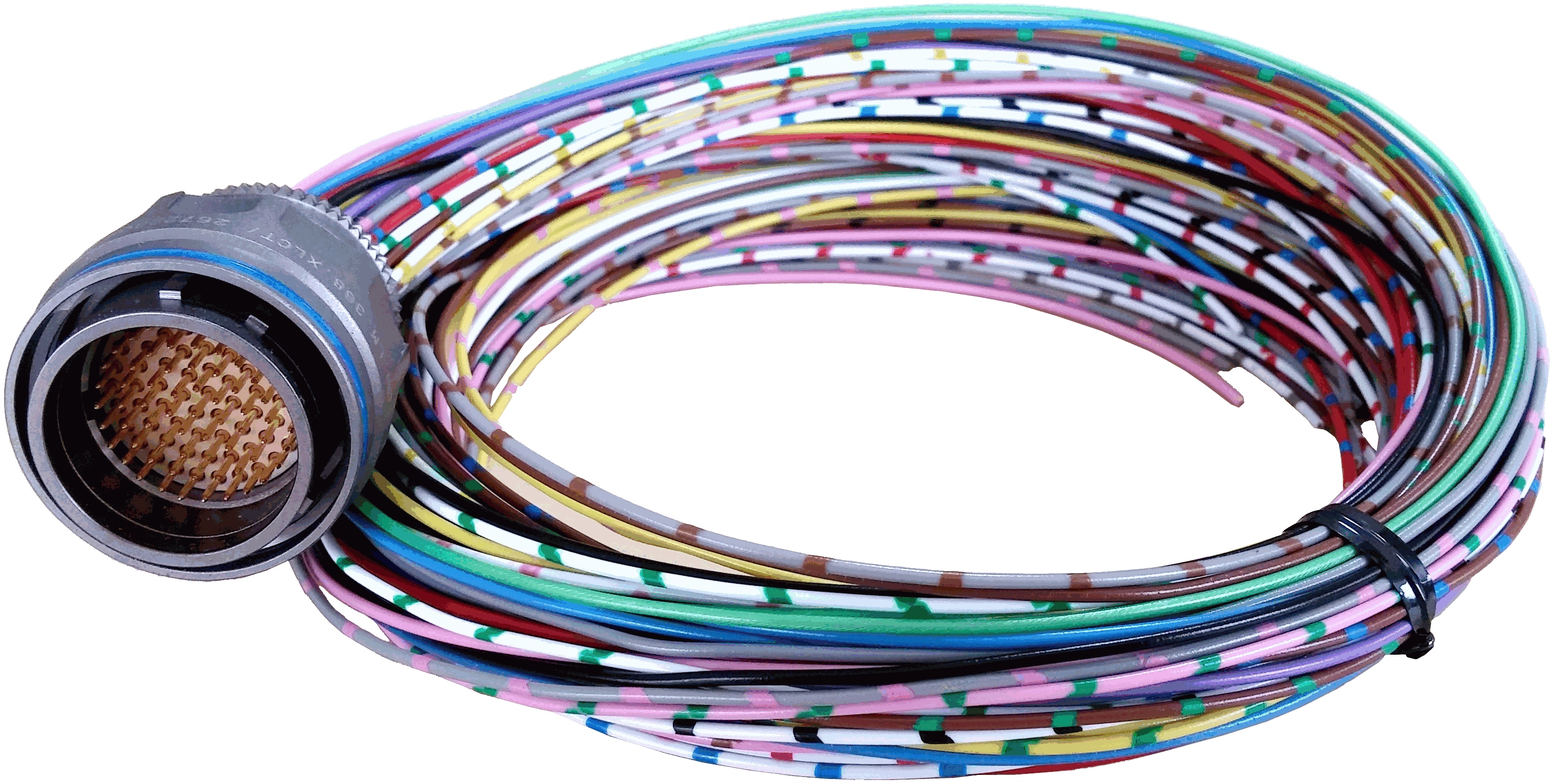 |
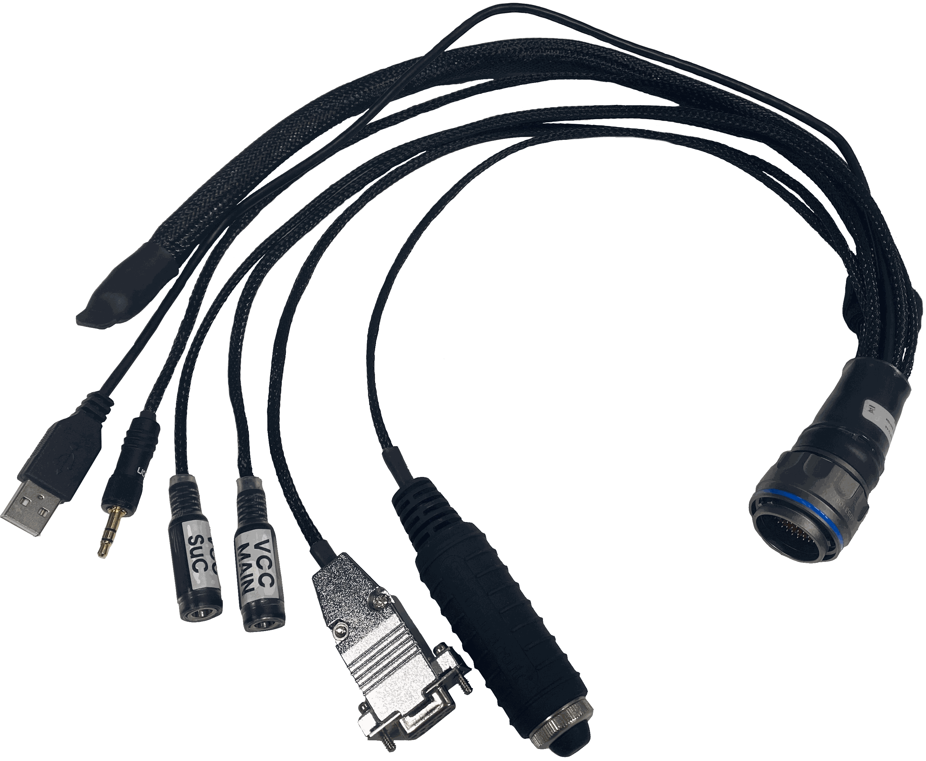 |
| Harness available on demand with the Embention reference P001114 | Harness available on demand with the Embention reference P007043 |
Dimensions
- Harness Blue 68P wire gauge: 22 AWG
- Cables length: 52 cm
-
Harness plug dimensions:
Connector FGW.LM.368.XLCT dimensions (cm)
Pinout

Veronte Harness Blue 68P
The pinout of this harness is the same as the Veronte Autopilot 1x pinout above. The color code of the harness wires is given below.
Warning
Check the pin number before connecting. The color code is repeated 3 times due to the amount of pins. First section (yellow) corresponds to pins 1-30, the second section (blue) to pins 31-60 and the third one (red) to pins 61-68. Pin number increases following the black line of the pictures above: counterclockwise for the connector and clockwise for the plug.
| PIN | Color Code | PIN | Color Code |
|---|---|---|---|
| 1 | White | 35 | Gray |
| 2 | Brown | 36 | Pink |
| 3 | Green | 37 | Blue |
| 4 | Yellow | 38 | Red |
| 5 | Gray | 39 | Black |
| 6 | Pink | 40 | Violet |
| 7 | Blue | 41 | Gray - Pink |
| 8 | Red | 42 | Red - Blue |
| 9 | Black | 43 | White - Green |
| 10 | Violet | 44 | Brown - Green |
| 11 | Gray - Pink | 45 | White - Yellow |
| 12 | Red - Blue | 46 | Yellow - Brown |
| 13 | White - Green | 47 | White - Gray |
| 14 | Brown - Green | 48 | Gray - Brown |
| 15 | White - Yellow | 49 | White - Pink |
| 16 | Yellow - Brown | 50 | Pink - Brown |
| 17 | White - Gray | 51 | White - Blue |
| 18 | Gray - Brown | 52 | Brown - Blue |
| 19 | White - Pink | 53 | White - Red |
| 20 | Pink - Brown | 54 | Brown - Red |
| 21 | White - Blue | 55 | White - Black |
| 22 | Brown - Blue | 56 | Brown - Black |
| 23 | White - Red | 57 | Gray - Green |
| 24 | Brown - Red | 58 | Yellow - Green |
| 25 | White - Black | 59 | Pink - Green |
| 26 | Brown - Black | 60 | Yellow - Pink |
| 27 | Gray - Green | 61 | White |
| 28 | Yellow - Green | 62 | Brown |
| 29 | Pink - Green | 63 | Green |
| 30 | Yellow - Pink | 64 | Yellow |
| 31 | White | 65 | Gray |
| 32 | Brown | 66 | Pink |
| 33 | Green | 67 | Blue |
| 34 | Yellow | 68 | Red |
Dev Harness 1x 4.8
This harness has some connectors already implemented for easy operation. Below is detailed information on which pins these connectors are connected to:
| Connector | PIN | Signal |
|---|---|---|
| Main VCC | 65 | GND |
| 66 | GND | |
| 67 | VCC | |
| 68 | VCC | |
| SuC VCC | 47 | GND |
| 48 | V_ARB_VCC | |
| RS232 Connector | 19 | RS 232 TX |
| 20 | RS 232 RX | |
| 21 | GND | |
| Maintenance Button | 31 | I2C_CLK |
| 32 | I2C_DATA | |
| Jack Connector | 18 | GND |
| 55 | EQEP_A | |
| USB | 60 | V_USB_DP |
| 61 | V_USB_DN | |
| 62 | USB_SHIELD_GND |
Flight Termination System (FTS)
Veronte Autopilot 1x integrates two different FTS pins (42 and 43):
FTS1 - Deadman (Pin 42): On this pin, Autopilot 1x outputs a square wave with A = ~5ms and B = ~5ms (3.3V). Its frequency can be higher right after the rebooting (around 300-400Hz), but A and B must be always < 8ms.
FTS2 - !SystemOK (Pin 43): Its output is 0V when the system is working as expected and 3.3V when some error is detected. In detail, pin 43 goes high if A > 8ms or B > 8ms in the deadman signal sent by the Main Processor Unit (MPU).
© 2026 Embention. All rights reserved.