Landing
Landing guidance is used to generate the flying path the aircraft will follow when landing on a certain runway. The generated path is not directly indicated by the user as in the cruise guidance (which is defined in the Mission menu), instead a trajectory is generated based on the parameters detalied later in this section. Below, find all the information to be defined by the user accompanied by the corresponding Figures showing the location of these parameters on the menu.
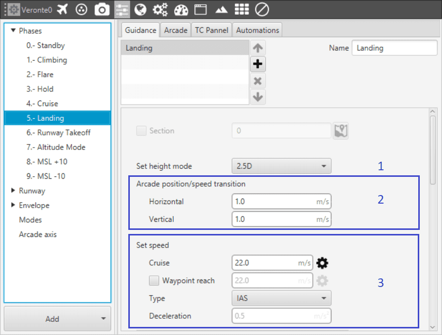
Landing Guidance menu (I)
- Set height mode: the height mode indicates how the aircraft will perform the landing path. The only one available for landing is 2.5D.
2.5D mode: the vehicle goes from the altitude at which it enters the phase with landing guidance to the beginning of the route in a diagonal trajectory (it follows a 3D trajectory that connects the two points) with a flight path angle, giving priority to horizontal over vertical guidance.
Arcade position/speed transition: if Arcade mode is configured, then the trajectory generated (position) is not followed and instead the aircraft moves according to the commanded speed. The parameters here (horizontal and vertical speed ) serve as an upper-threshold for when the aircraft’s guidance should be position-based, even in Arcade mode. This parameters are mainly useful for platforms like multicopters.
Set speed: this option sets the speed that the vehicle will have during the landing manoeuvre.
In Cruise the user sets the velocity modulus.
The option Waypoint reach is used to indicate the speed at which the platform will reach the waypoints, i.e. it will travel along the path with the speed indicated in the option Cruise and then it will decelerate or accelerate to the speed indicated in Waypoint reach.
The defined speed can be IAS (indicated airspeed) or Ground speed. Normally, IAS is used for airplanes and Ground speed for multicopters.
Deceleration: maximum allowed acceleration/deceleration in order to meet the desired velocity.
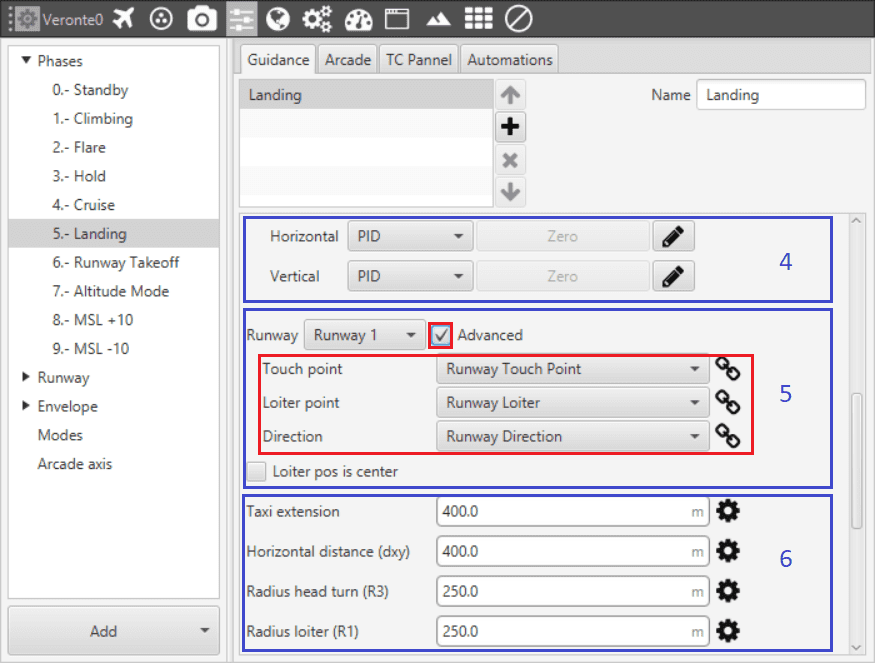
Landing Guidance menu (II)
Guidance control: a horizontal and vertical PID controller is defined here. Its purpose is to adjust the platform’s actual trajectory to the desired one. When clicking on Horizontal or Vertical, a pop-up window will open where the control parameters should be introduced – for more information on the latter subject check the Blocks.
Loiter and runway position: here the user defines the loiter and runway positions. The default option is to have the have the loiter and runway positions defined in Runway. If the Advanced option is chosen, then the user needs to define three parameters. By clicking on
 different options will be displayed:
Touchpoint: defines the touchpoint of the runway. This point can be defined by introducing its latitude, longitude and altitude; or else it can be chosen from a list of options that includes the waypoints defined in Mission, among many others.
Loiter point: defines the loiter point. This point can be defined by introducing its latitude, longitude and altitude; or else it can be chosen from a list of options that includes the waypoints defined in Mission, among many others.
Runway direction: defines the runway direction. I can be defined as an angle with respect to the magnetic north; or else it can be chosen from a list of options like runway directiom, tailwind direction, etc.
If the box Loiter pos is center is ticked the defined loiter point will be the center of the loiter circular trajectory. On the contrary, the loiter trajectory can pass throught that point.
Trajectory distances: here the user defines some of the trajectory distances. This distances match the trajectory patches lengths \(L\) or are proportional to them. See the explanation below for more information on every patch.
Radius loiter R1: radius of the descending loiter for the aircraft to reach an altitude suitable to perform the landing manoeuvre (\(L_1 \propto \pi R_1\)).
Radius Head Turn R3: radius of the last turn in order to face the runway direction (\(L_3 \propto \pi R_3\)).
Horizontal extension (dxy): distance before the head of the runway. At the end of this length, touchdown is expected.
Taxi extension: distance from touchdown to where the aircraft is brougth to a full stop.
Some patches don’t have an associated user-defined distance, and are automatically calculated by the landing guidance algorithm: they depend on some of the above distances and other parameters defined below.
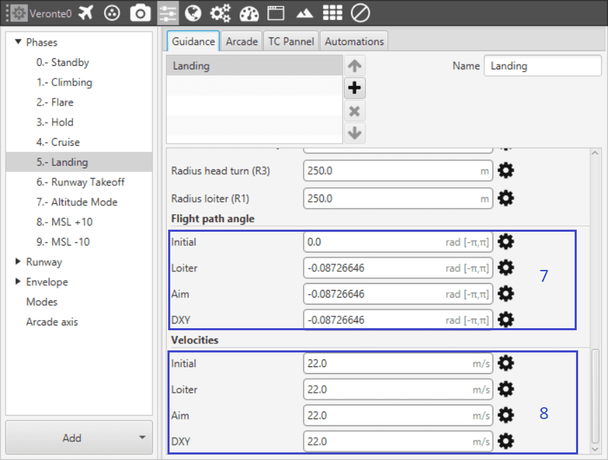
Landing Guidance menu (III)
Trajectory flight path angles: here the user defines the desired trajectory flight path angles for each of the patches of the trajectory. See the explanation below for more information on every patch.
Initial: desired flight path angle \(\gamma_{0}\) of patch 0.
Loiter: desired flight path angle \(\gamma_{1}\) of patch 1.
Aim: desired flight path angle \(\gamma_{2,3}\) of patches 2 and 3.
DXY: desired flight path angle \(\gamma_{4}\) of patch 4.
Trajectory velocitites: here the user defines the desired trajectory velocities for each of the patches of the trajectory. See the explanation below for more information on every patch.
Initial: desired velocity \(v_{0}\) of patch 0.
Loiter: desired velocity \(v_{1}\) of patch 1.
Aim: desired velocity \(v_{2,3}\) of patches 2 and 3.
DXY: desired velocity \(v_{4}\) of patch 4.
The generated trajectory of the landing guidance defines the route that the aircraft follows from the point when the phase with this guidance is entered, to the point where it touches the ground – see the Figure below. The landing route has two parts, being decomposed into 6 patches.
- First part: descending loiter used to descend from the cruise altitude to an altitude where the heading manoeuvre towards the runway can be performed.
Patch 0: this patch is generated from the point the landing phase is entered to where the loiter is located. Variables that influence this patch are \(\gamma_{0}\), \(v_{0}\), altitudes \(H_0\) and \(H_1\), and Loiter point position.
Patch 1: the patch length (\(L_1\)) will depend on the amount of loops on the loiter. The latter can go from 0 to more than 1 loop, depending on the altitude necessary to descend/ascend. Variables that influence this patch are \(\gamma_{1}\), \(v_{1}\), altitudes \(H_1\) and \(H_2\), and Radius loiter R1.
The loiter exiting point altitude is computed so that patches 2 to 5 can be performed following their desired \(v\) and \(\gamma\). So it exists the possibility of starting the landing manoeuvre at a lower altitude thant the exiting point of the loiter. In that case, the loiter would be used to ascend. If the aircraft starts the landing phase at an altitude similar to the one of the loiter (defined in point 6), then the loiter patch is simplified into a turn – during the turn the altitude can still be adjusted, and the turn’s length will depend on the latter.
- Second part: final approach of the landing, which consists on turning, facing the runway and touchdown.
Patch 2: patches 3 and 4 need to matcht the distances defined above. Patch number 2 will conect the exit of the loiter patch with the beginning of patch 3. Variables that influence this patch are \(\gamma_{2,3}\), \(v_{2,3}\), altitudes \(H_2\) and \(H_3\), and Loiter point and Touchpoint positions.
Patch 3: turning of the aircraft to face the runway. Variables that influence this patch are \(\gamma_{2,3}\), \(v_{2,3}\), altitudes \(H_3\) and \(H_4\), and Radius Head Turn R3.
Patch 4: at the end of the patch the aircraft lands. Variables that influence this patch are \(\gamma_{4}\), \(v_{4}\), altitude \(H_4\), and Horizontal extension (dxy).
Patch 5: taxi extension for the aircraft to slow down.
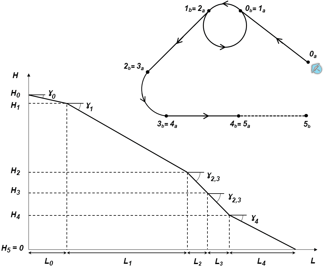
Landing Route
Guidance-generated Variables
Landing guidance generates a three-dimensional trajectory, as well as a set of variables which can be used in te control guidance. The list of variables is the following:
Desired position.
Track position.
Track state (current patch, last patch).
Desired latitude, desired longitude, desired WGS84, desired MSL, desired AGL.
Desired velocity.
Desired front groundspeed, desired lateral groundspeed, desired velocity down.
Desired tangential acceleration.
Desired IAS.
Guidance north error.
Guidance east error.
Guidance down error.
Desired body velocities.
Desired velocities north, east, down.
Desired heading, FPA and bank.
Route-guidance distance - tangential component.
Route-guidance distance - horizontal component.
Route-guidance distance - perpendicular component.