HIL
Professional Hardware In the Loop (HIL) Simulator package is a powerful tool for Veronte Autopilot integration, development and operator training; permitting to extensively operate the system in a safe environment, prior to conducting real flight operations
There are 2 configuration items on Veronte Pipe, one relating communications between the application and the X-Plane simulator and another one refereeing the autopilot configuration. Users can find the complete process including X-Plane settings in Professional HIL.
Autopilot Configuration
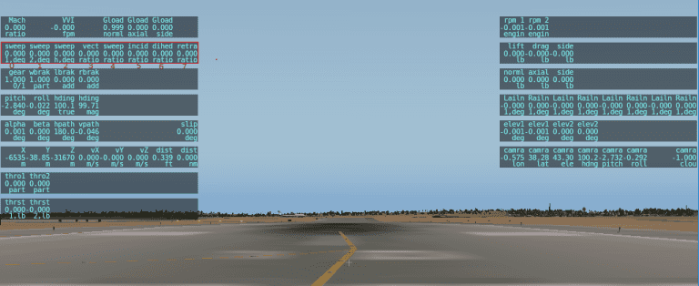
HIL simulation tab is available within Veronte Autopilot setup toolbar. The user can link the variables on Veronte Autopilot with the corresponding ones in X-Plane simulator.
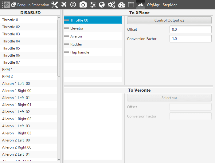
Veronte Pipe – HIL Setup
In this panel, X-Plane variables are available on the left side (Disables). In addition, it can be seen two section more To XPlane and To Veronte.
In order to configure the simulation variables, users have to:
Enable the ones that have been configured in the aircraft model (Plane Marker). Just drag and drop them into To Xplane section.
Warning
Always make sure that surfaces are moving in the right direction and with the correct deflection angle.
To avoid mistakes is possible to set a positive fixed deflection (Control Tab) in Standby phase for all surfaces and control surface deflections in the X-Plane model.
Surface control variables are of two types:
Radians measure (variables with numbers)
Degrees measure (variables with no numbers)
Once X-Plane variables have been enabled, select the actuator variable (Control Output) that matches with the ones in Veronte autopilot. A new window will be displayed for each variable.
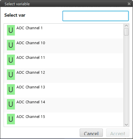
HIL Panel
Set a Conversion Factor or Offset, if it is necessary. Conversion factor multiplies the Veronte output signal and can be used in case units on Veronte and the X-Plane simulator do not match (Surfaces in X-Plane move normally in a [-1,1] range). The following operation allows to converting an angle [deg] measure to the X-Plane form:
(Angle + Offset) Conv.Factor = …
When Angle and Offset are measured in [rad] and the Conversion factor is a constant (normally it can be calculated as 1/(deflection angle in [rad]).
In the case of [rad] measures, the Conversion factor must be set in 57,29578 ([deg]-[rad] conv. factor).
Finally, it is necessary to configure the communication between Veronte Pipe and X-Plane, see section below.
Adding New variable
When there is any varible that doesn’t appear in Veronte Pipe, it is possible to add a new one and linked it with the one correspondent in X-Plane. To do this, user have to edit the file “XplaneDATAGroupConfig.xml”.
This file contains the following information:
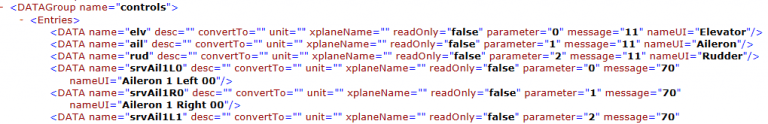
XplaneDATAGroupConfig.xml
Data name: variable’s name in X-Plane.
Parameter and message: these values must be set correctly to link the variables.
nameUI: variable’s name in Veronte Pipe. User can type the name that will appear in the list.
Consider the following example that explains how to add a new variable. Imagine you have a wing with variable incidence (configurable in Plane Maker) and this parameter doesn’t appear in Veronte Pipe.
First, user have to check the variable’s name, parameter and message in X-Plane. Open X-Plane and go to Setting/Data Input & Output.
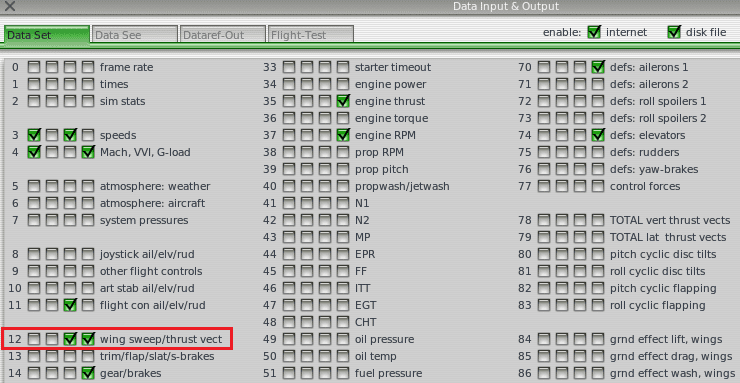
Data Input & Output
The message is the number that appears next to each variable. In this case, the data related to a wing with variable incidence is “wing sweep/thrust vect” (see X-Plane manual), so message has to be set with 12. Variable’s name and parameter can be found in the following image:
X-Plane
Variables’s name is incid and parameter is 5. To find out the parameter’s number, user have to count starting from “0” and the left. Once all data is known, it is possible to edit the .xml file and add the new variable with a text editor. The result is shown in the following image:

XplaneDATAGroupConfig.xml
The nameUI has been set as Canard and this will be displayed in the variables list. Now, user can simulate this variable in X-Plane from Veronte Pipe.
Veronte Pipe communications
In order to start the simulation, select the HIL option (1) on the Veronte Unit, this is available on the side menu . Popup screen will be displayed (2) for selecting the type of simulation and configuring the parameters.
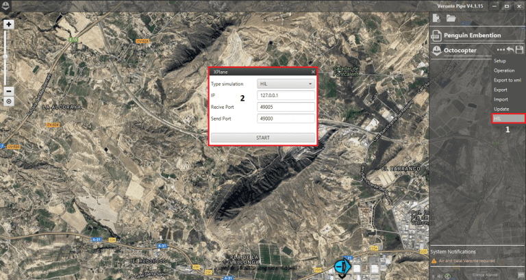
Veronte Pipe – HIL Communications
Changing the default values is only recommended for advanced users. Press start in order to start the data transfer between X-Plane and Veronte Autopilot.
Warning
The simulation must be started when the aircraft is in the Initial phase (the one that gets in once is powered). In this phase the X-Plane will simulate the GPS signal to locate the autopilot in the place indicated by the airport on X-Plane.