Climb
Climb guidance is used to make the aircraft climb from the start of the phase to another altitude. Commonly, this guidance is used after the take-off to fly from the ground to cruise altitude through a loiter point, but it can be employed for other purposes.
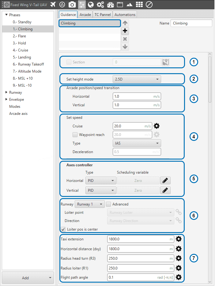
Climbing Guidance Parameters
The climbing path is automatically generated and is not directly shown to the user until the aircraft enters this phase. This is due to the algorithm recalculating the path each time to take into account the aircraft’s actual flight conditions and the user’s indicated parameters. Below, the parameters shown above are going to be described. Later, a brief description of the algorithm and its behavior in different possible situations will be presented:
Section. This option allows the user to select the first path to be flown by the aircraft in cruise mode. Section selection is disabled in this mode. As already said, in this phase the path can not be directly indicated by the user as it is done in cruise mode (see Mission menu for more details).
Set height mode. Height mode indicates how the aircraft will perform the route. Height mode in Climb guidance is fixed to 2.5D type. In 2.5D, the aircraft will fly from current altitude at a desired flight path angle, FPA. Go below for more information about this topic.
Arcade position/speed transition In Arcade mode the trajectory generated (position) is not followed and instead the aircraft moves according to the commanded speed. The horizontal and vertical speed parameters serve as the upper-thresholds for when the aircraft’s guidance should be position-based, even in Arcade mode. This parameters are mainly useful for platforms like multicopters.
Set speed: this option sets the desired aircraft speed during the manoeuvre.
Cruise: Cruise Lets the user set the velocity modulus of the guidance. This velocity can be slightly modified by the autopilot control algorithms.
Waypoint reach indicates the speed at which the platform will reach the waypoints of the path, i.e. it will travel along the path with the speed indicated in the option Cruise and then it will decelerate or accelerate to the speed indicated.
Defined speed can be IAS (indicated airspeed) or Ground speed. Normally, IAS is used for airplanes and Ground speed for multicopters.
Deceleration: maximum allowed acceleration/deceleration to meet the desired velocity.
Axes controller: Horizontal and Vertical PIDs controllers to guarantee stability of guidance loop are defined here. Their purpose are to adjust the platform’s actual trajectory to the desired one. When clicking on Horizontal or Vertical, a pop-up window will appear where the control parameters should be introduced – for more information on the latter subject check Loop menu.
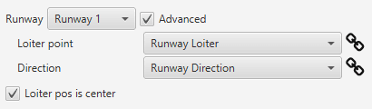
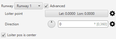
Loiter and runway position: By default, loiter and runway positions and direction are defined in Runway menu and the user selects the runaway. However, this parameters can by modified clicking on “Advanced”. Then, the user can choose between the two available option definitions by clicking on
 :
:
Runway and loiter position options and alternative configurations
Loiter point: defines the loiter point. By default, this point is the runaway’s loiter. But the user can select in the drop-down list any other previously defined point. This includes waypoints defined in Mission, among many others. Alternately, the user can manually define the Loiter point.
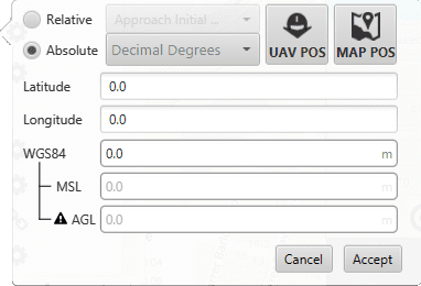
Loiter Point Selection Menu
Runway direction: defines the runway direction. Again, by default, is the same as the selected runaway. It can be also chosen from a list of options including runway direction, tailwind direction, etc. Alternately, it can also be defined as an angle with respect to the magnetic north.
If the box Loiter pos is center is ticked, the defined loiter point will be the center of the loiter circular trajectory. In case of not, the circular loiter trajectory will pass through that point.
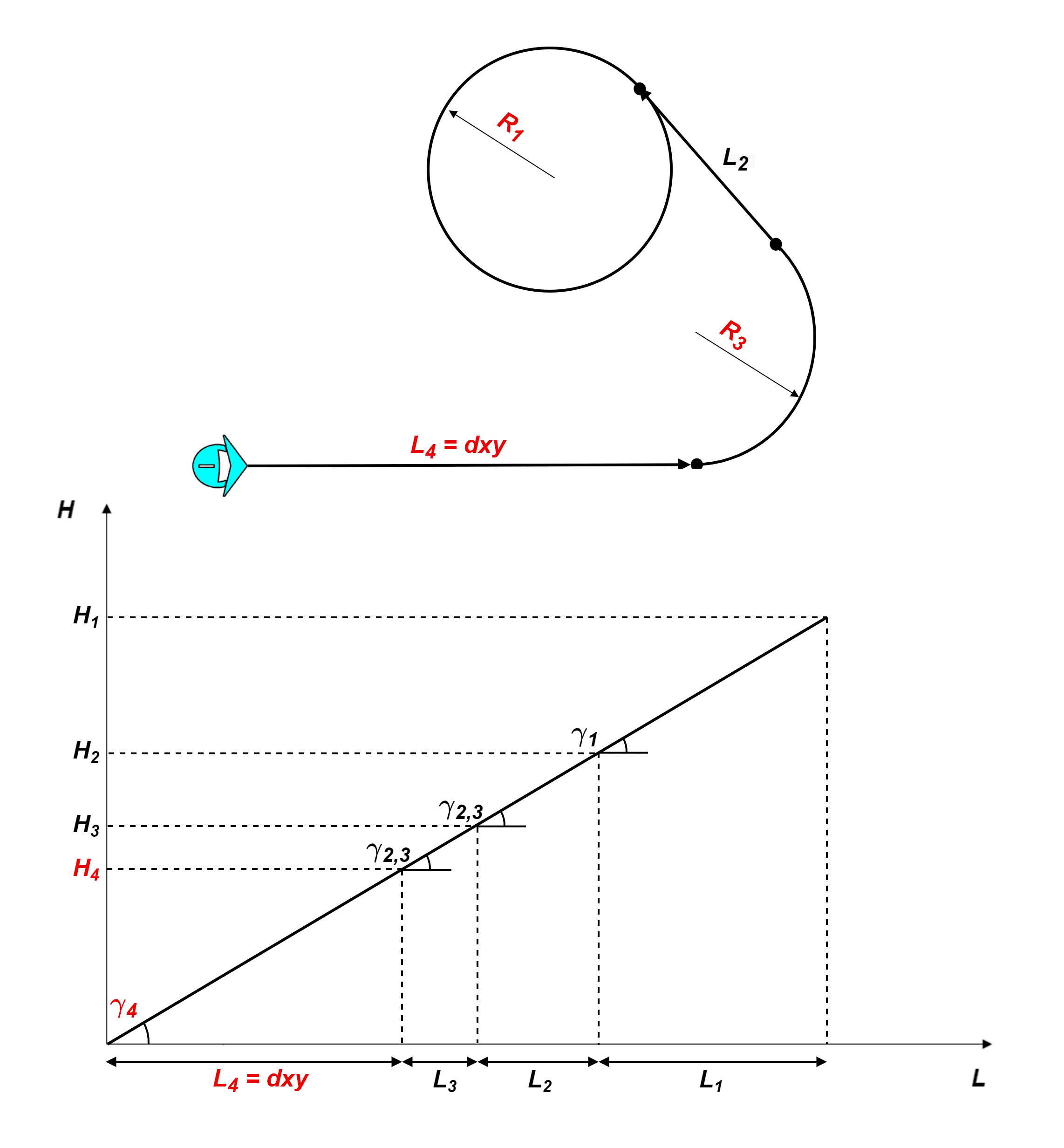
Climb route top and front views with parameter identification
Route: here is where the user can set some of the the climbing path parameters (those highlighted in red on the above diagram). First, the user defined parameters are described and, after, some considerations about the climb algorithm behavior will be explained:
Taxi extension: this parameter does not apply to this algorithm.
Horizontal extension (dxy): absolute ground distance of the first path, \(L_4\): from the star of the climb to the start of the turn that faces the loiter path. This distance will remain fix always and it will also fix \(L_4\) path’s final point height, \(H_4\). More information below.
Radius Head Turn (R3): radius of the turn to head the platform towards the loiter.
Radius loiter (R1): radius of the ascending helix path to reach the loiter height.
Flight Path Angle. The \(FPA\) is the angle at which the aircraft will climb. Before the algorithm execution, all Flight Path Angles, \(\gamma_i\), are equal: \(FPA = \gamma_4 = \gamma_{2,3} = \gamma_1\). The algorithm can modify \(\gamma_{2,3}\) and \(\gamma_1\). In that case, the Flight Path Angle option will serve as the upper threshold.
Each one of this parameters can be disabled, enabled or linked to an Operation Guidance defined by the user clicking on
.
Climbing guidance parameters behavior
The climbing track is not fix, the algorithm recalculates the paths each time to take into account the aircraft position and the user’s parameters. The trajectory usually has 4 paths, excluding the final loiter path:
General trajectory description:
\(L_4\) is the first path. The user can set the horizontal length, \(dxy\), the direction (in Runway direction) and the path’s final point height, \(H_4\) with the defined Flight Path Angle. This is very relevant, as seen later. The path length can not be zero.
\[ \begin{align}\begin{aligned}\gamma_4 = FPA\\H_4 = dxy*\tan(\gamma_4)\end{aligned}\end{align} \]\(L_3\): Circular turn to head the platform towards the loiter. The user can set the radius, \(R_3\). Is possible to set this path to zero and disabled it clicking on
. The FPA, \(\gamma_{2,3}\), can be modified by the algorithm.\(L_2\): Straight path that reaches the climbing loiter point. This path is completely automatic generated. Its FPA, \(\gamma_{2,3}\), can be modified by the algorithm.
\(L_1\): Ascending helix path to reach the loiter height. The user can set the radius, \(R_1\).
Loiter height effect: Loiter height’s, \(H_c\), modifies the algorithm general behavior. Depending on whether \(H_c\) is bigger or smaller than \(H_2\) or smaller than \(H_4\) the algorithm will modify some parameters, in particular the flight path angles:
\(H_2 < H_c\). Is the general case. In this situation, no corrections will be applied as shown below and \(\gamma_{2,3} = \gamma_1 = FPA\).
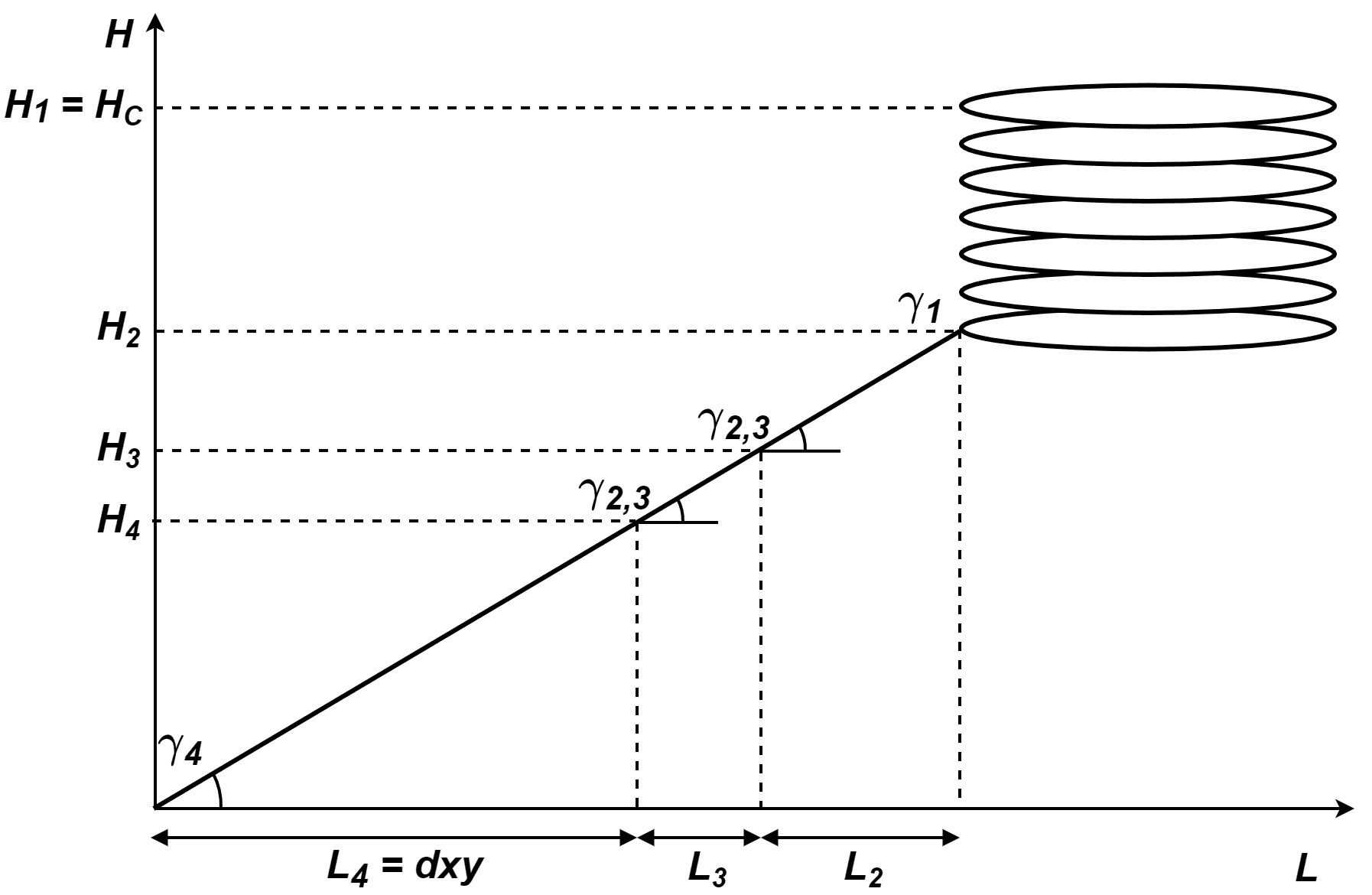
Climbing heights when \(H_2 < H_c\)
\(H_4 < H_c < H_2\): In this case, the algorithm will compute a new \(\gamma_{2,3}\) to avoid surpassing the loiter’s height and \(\gamma_{1}\) will be zero.
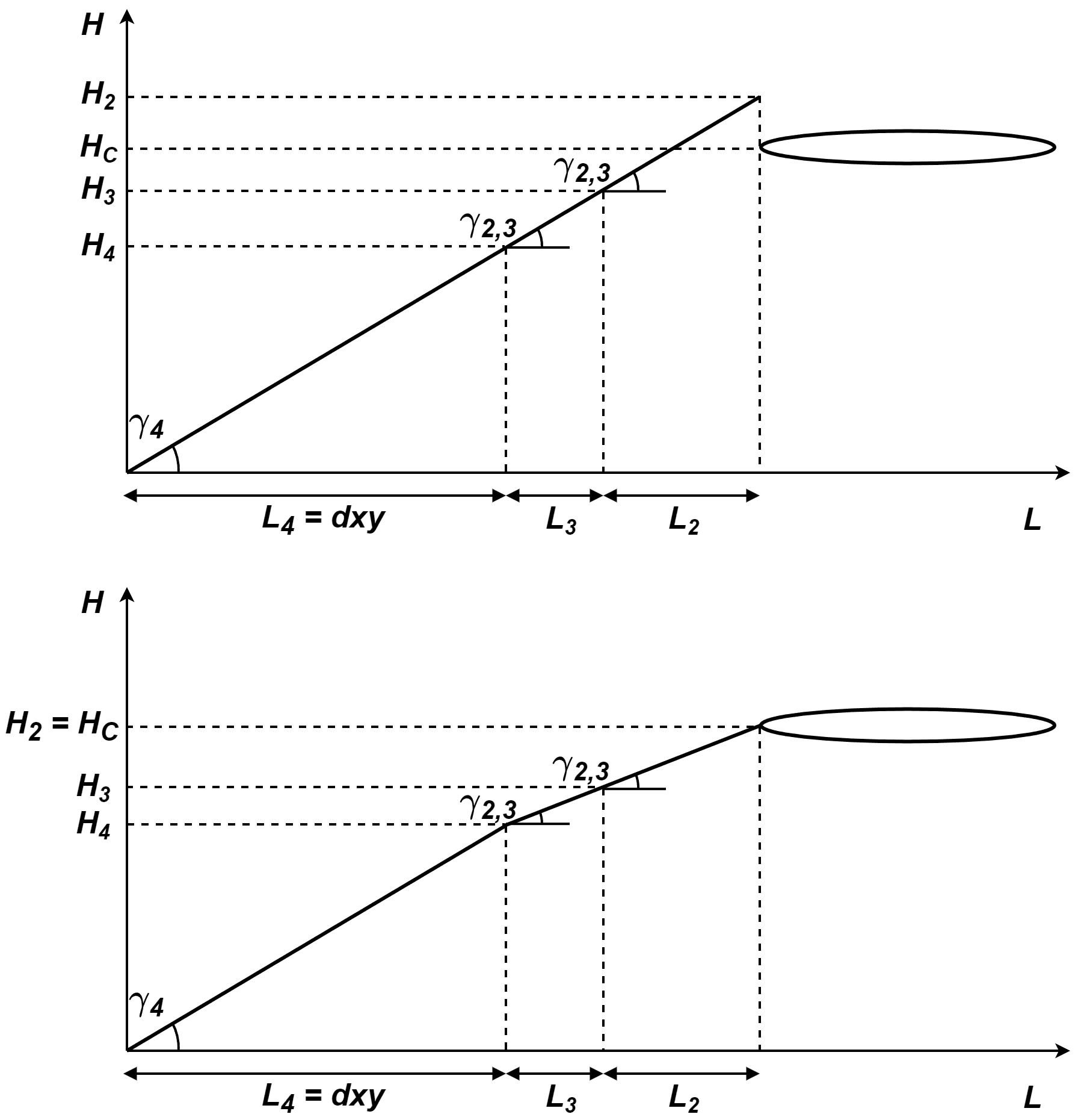
Climbing heights when \(H_4 < H_c < H_2\)
\(H_c < H_4\): In this case, the algorithm will force \(H_c = H_4\). So \(H_4\) will be the new loiter height keeping \(\gamma_{4} = FPA\) and the other flight paths angles equal to zero, \(\gamma_{2,3} = \gamma_1 = 0\).
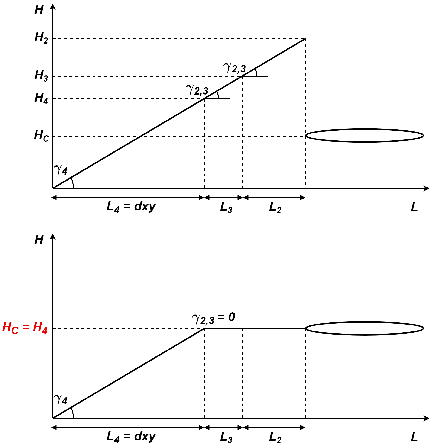
Climbing heights when \(H_c < H_4\)
Guidance-generated Variables
Climbing guidance generates a three-dimensional trajectory, as well as a set of variables which can be used in the control loops – check Loop menu.
The list of variables is the following:
Desired position.
Track position.
Track state (current patch, last patch).
Desired latitude, desired longitude, desired WGS84, desired MSL, desired AGL.
Desired velocity.
Desired front groundspeed, desired lateral groundspeed, desired velocity down.
Desired tangential acceleration.
Desired IAS.
Guidance north error.
Guidance east error.
Guidance down error.
Desired body velocities.
Desired velocities north, east, down.
Desired heading, FPA and bank.
Route-guidance distance - tangential component.
Route-guidance distance - horizontal component.
Route-guidance distance - perpendicular component.