Connections
Here the user can configure the Input/Output ports of the autopilot. Veronte Autopilots have 68 pins, which are shown on the Pipe menu Setup -> Connections – see the Figure below. When selecting a port its pin is displayed on the panel.
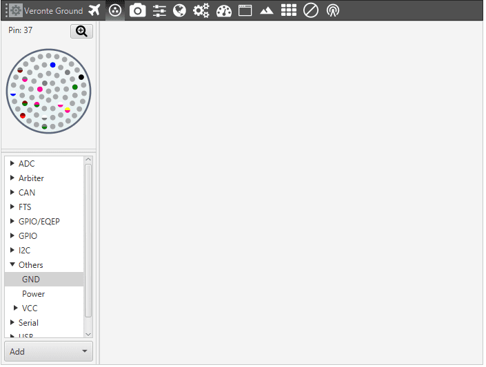
Setup – Connections – GND Pins Displayed
To know about a particular pin’s colour scheme, the user shoulg click the button on the top right corner above the 68 pin connector picture – see the Figure below.
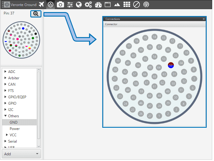
Connection 68 Pin Colour Scheme
Warning
The colour code is referred to the single Veronte. For 4x Veronte refer to 4x Hardware Installation.
4x Hardware Installation – Electrical .
Finally, depending on the configurable port selected the user will need to provide different parameters. The following table shows the type of connections available for configuration in Veronte Autopilot.
Field |
Description |
|---|---|
ADC |
Analog-to-Digital Converter. |
Arbiter-SuC |
Safety micro controller |
CAN |
Configurable Controller Area Network bus A & B. |
GPIO/EQEP |
Enhanced Quadrature Encoder Pulse Input. |
GPIO |
Veronte input/output signals. |
I2C |
I2C (Inter-Integrated Circuit) bus. |
PWM |
Pulse Width Modulation configuration. |
Serial |
Configurable Serial ports RS232 & RS485. |
Each connection is associated with a specific pin number. For more details see the section Hardware Installation – Electrical .