 Veronte
Unit name
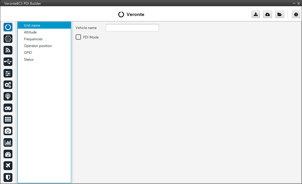
Unit name section
Vehicle name: The user can define the name of the configuration.
PDI Mode: It can be enabled or disabled. PDI mode allows the user to change the setup if BCS is not in INI phase.
Warning
Not being in PDI mode, the user cannot do out of the INI phase:
Reboot BCS
Change BCS setup (i.e. save to SD card)
Enter manually in maintenance mode
The variable ‘System error’ prevents operation in normal mode (not PDI mode). A list of all errors that can cause this bit to be set can be found in the Activation system error bits section of the 1x Software Manual.
If BCS has ‘sensor errors’ and it is in normal mode (not PDI mode), the user will not be able to switch to another flight phase, it will remain in INI phase.
Danger
PDI mode is intended for development purposes since, as detailed above, it allows flight phase changes with system, sensor and PDI errors.
It is highly recommended to limit its use to simulation and ground testing of peripherals during the development phase.
Therefore, as it is not advisable to operate in PDI mode, please disable it once the configuration is finished and intended to be used in flight.
Attitude
Deprecated
Frequencies
The frequency of the GNC task refers to the maximum working frequency of the core. In this case, 400 Hz, which is the maximum possible.
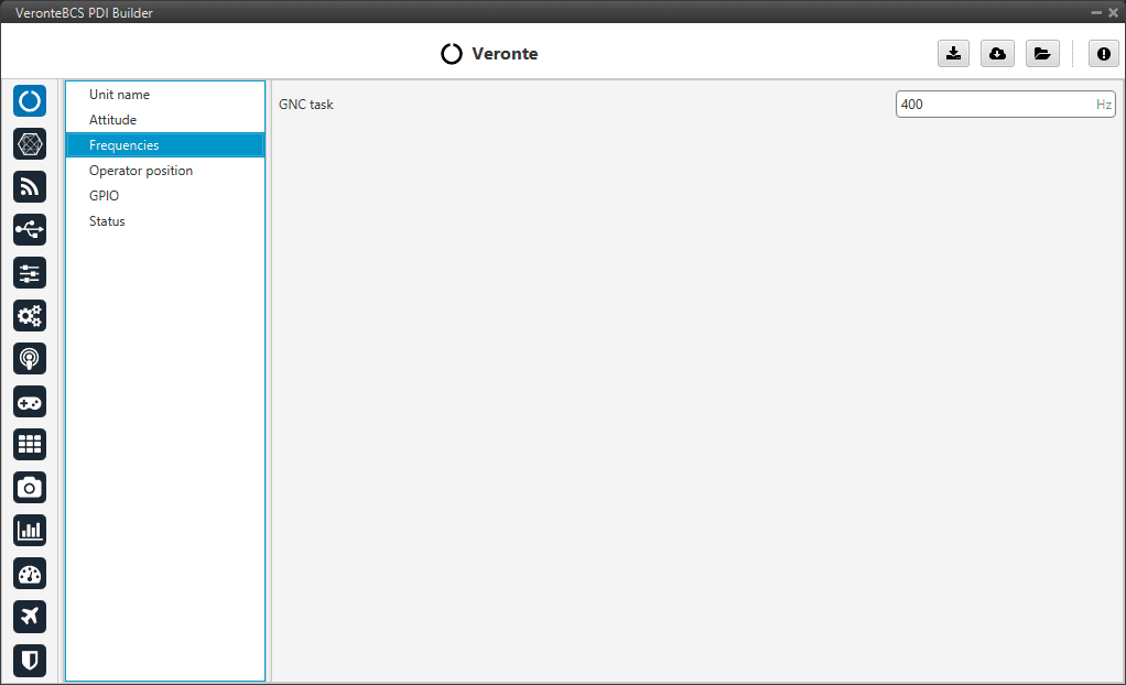
Frequencies section
Warning
Only 400 Hz can be used for simple configurations, so it is often necessary to reduce the frequency to 250-300 Hz. To find out why the user should reduce the GNC Task frequency, see Reduce GNC Task frequency -> Troubleshooting section of this manual.
Operator position
The operator position is the reference for the aircraft, which is used to calculate the distance allowed by the license.
Press  or
or  to switch between reference modes: valid ID and invalid ID.
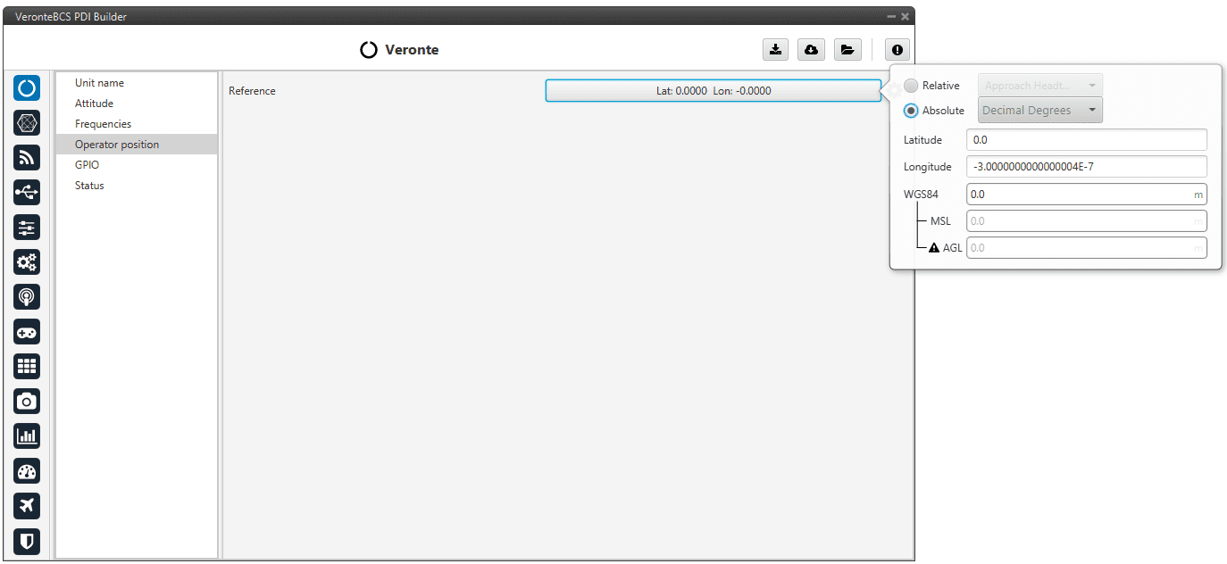
Operator position - Valid ID mode
The absolute position is a specific point defined. The relative position is defined as a Custom point in Veronte Ops, to know more read the Custom points section of Veronte Ops manual.
Tip
In operation, if the air unit does not have the license activated, it is recommended to set in the air unit (1x) the position of the ground unit (BCS). Remember to use 1x PDI Builder to configure the Autopilot 1x and the BCS PDI Builder to configure the control station BCS.
GPIO
In this tab each individual GPIO behavior can be configured:
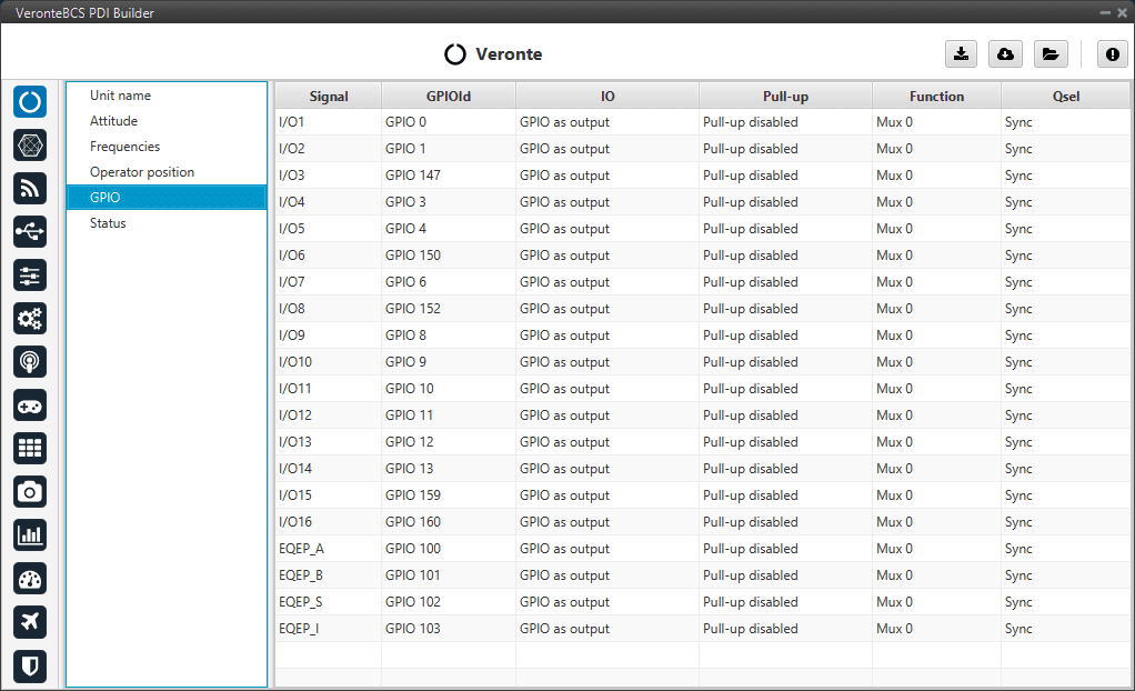
GPIO section
Signal: Pin ID as described in the Pinout section of the BCS user manual.
GPIOId: GPIO ID of the microcontroller.
IO: Define GPIO as an input or ouput.
Pull-up: Enable or disable the pull-up resistance.
Function: Mux 0: GPIO, Mux 1: PWM, Mux 2, Mux 3, etc. These are the different functionalities that the GPIO can have, this depends on the multiplexer.
Qsel: This is the “input qualification”, it is used to control how the value of a GPIO is evaluated. The available options are:
Sync: The value is taken as whatever is present at the time it is checked (synchronously). This is the default mode of all GPIO pins.
3 Samples: The value is checked 3 times and the value is only changed when the 3 times are the same.
6 Samples: Same as the previous one, but checking 6 times instead of 3.
ASync: No checks are performed. It is used when it is not used as GPIO.
Status
This option enables the periodic sending of the status message that Veronte Link uses to recognise the BCS.
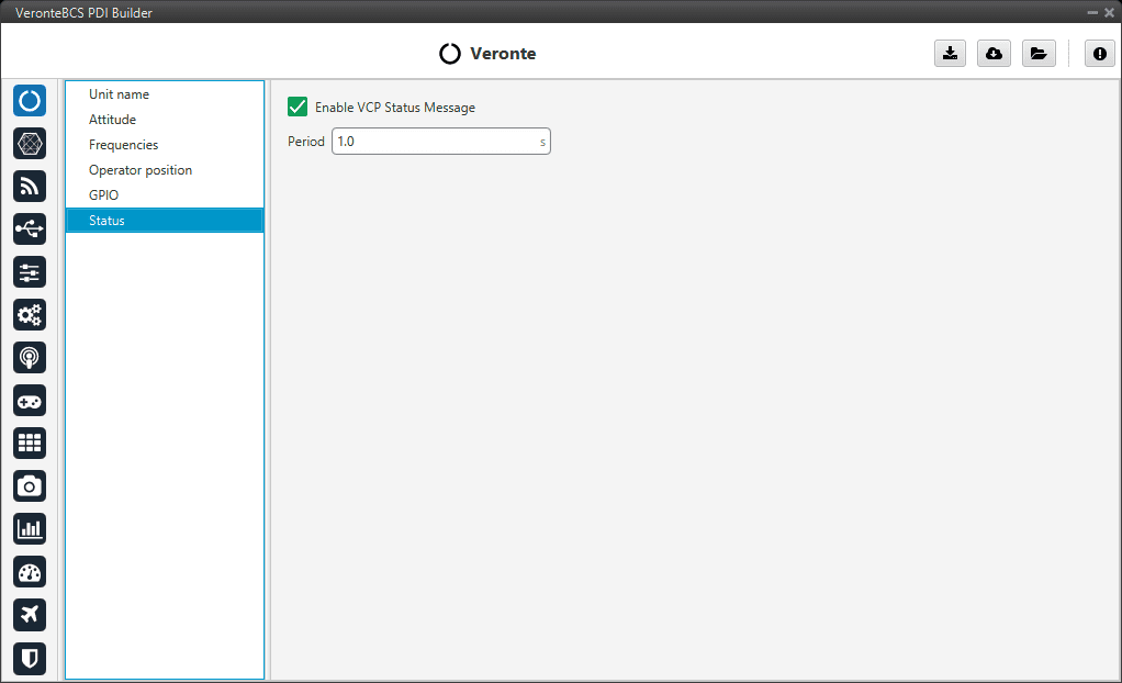
Status section
Period: Enter a desired period to send repeatedly the status message.
Note
VCP is the Veronte Communication Protocol. To know more, read the VCP user manual.