Configuration
Once the installation is finished, open BCS PDI Builder and select the unit.
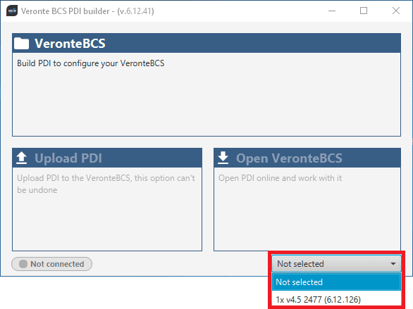
BCS selection
If it is correctly connected, it should appear in Normal mode, as shown in the figure below, or Maintenance mode.
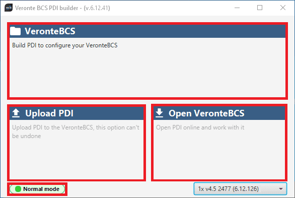
BCS PDI Builder - Normal mode
BCS unit can also appears as: Maintenance mode (loaded with errors) or Normal mode - Disconnected.
Note
Maintenance mode (loaded with errors) appears when something is wrong in the configuration. For more information, see Troubleshooting section of this manual.
The user can access now to 3 configuration options:
Veronte BCS: It allows the user to work with offline configurations. A previously exported BCS PDI can be opened and modified or it is possible to build a new one from the default configuration.
Upload PDI: A previously exported BCS PDI configuration can be imported to the linked BCS.
Open Veronte BCS: By clicking on this option, BCS PDI Builder configuration menu opens with the configuration (the PDI files) loaded in the connected BCS. Then, the user can modify it online.
Note
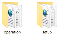
PDI files are configuration files. These files allow for modular control with improved version management. These PDI files are split in two folders. Each folder hold several .xml files:
Operation: This folder holds all the files related with the operations defined, such as waypoints, routes, operative parameters, runaways, etc.
Setup: This contains the configuration of the vehicle. All the control loops and their parameters, the definition of the flight phases and guidance commands, and the automations defined are stored here.
PDI files
Finally, click on ‘Open Veronte BCS’ to open the configuration and start editing. The different ‘buttons’ that can be seen in the initial menu of the BCS PDI builder are explained below.
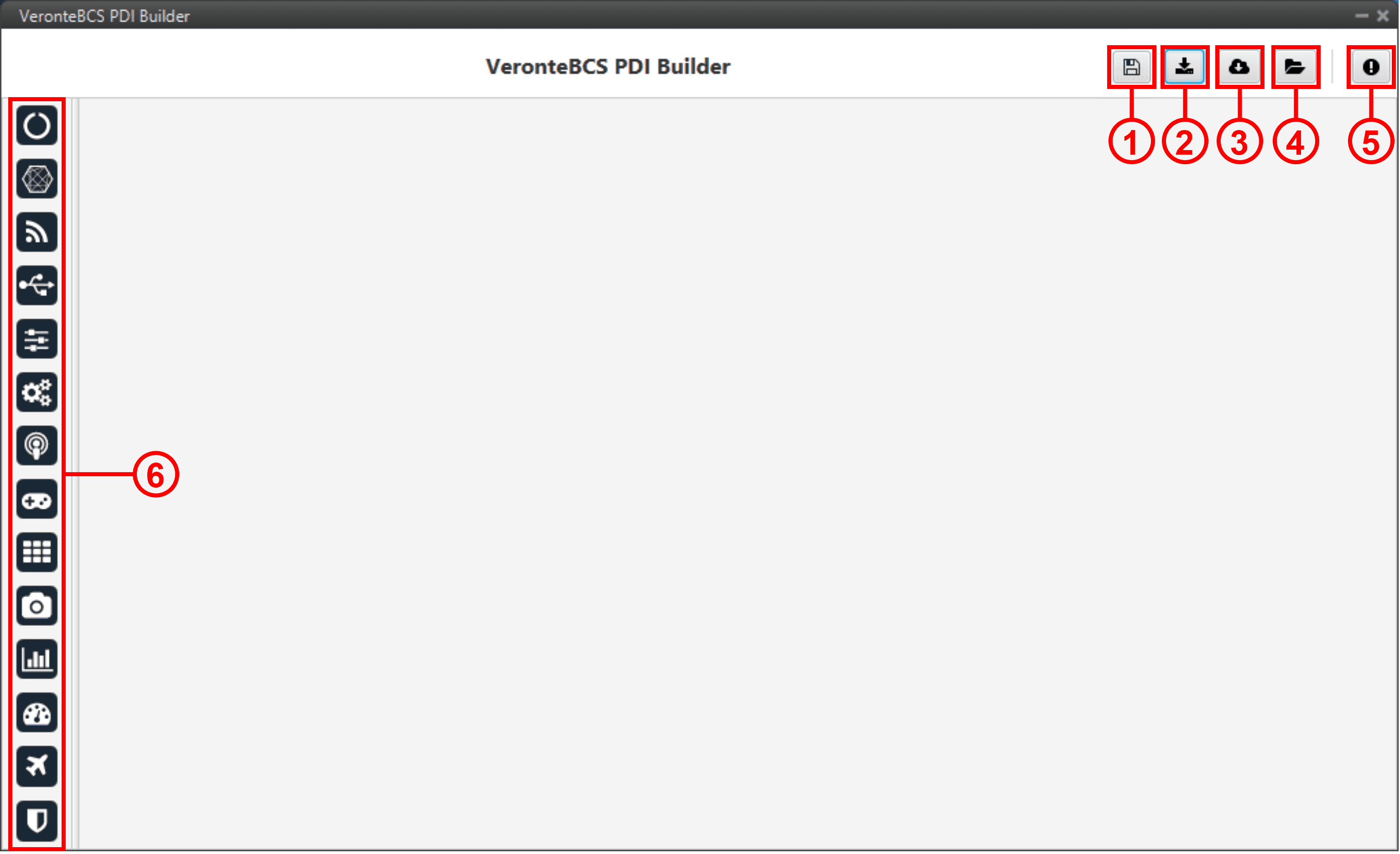
Initial menu
Save PDI: After changes are done, press on the save button to apply the changes.
While saving, a percentage of the progress of the saving process is displayed:
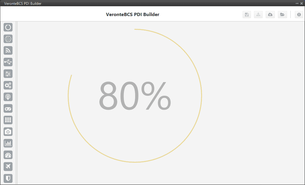
Save PDI
After saving any changes, BCS will RESET and the BCS PDI Builder software will close.
Danger
As Veronte BCS is reset, it is not advisable to save changes during flight tests.
Note
This button will only appear if a BCS is connected, i.e. when working offline this button will not be available.
Export PDI: After modifying a configuration, press the export button to store the configuration in the local storage. Users can store this configuration in an empty folder or in the folder where the previously imported configuration is stored. With the latter option, the “original” configuration will be overwritten by the one with the new changes. The user can choose between:
Download PDI: With this option the 2 folders with the PDI files are downloaded.
Download VER file: Download a .ver file with the configuration in binary. This option is only available ‘online’, otherwise it will be disabled.
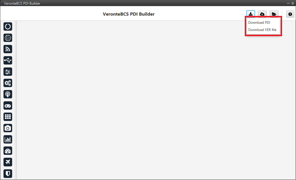
Download option
Import PDI from repo: The user can import a configuration file from the repo and modify it. After that, if the save button is pressed, this configuration will be uploaded on the BCS.
Import PDI from local storage: The user can import a configuration file from the local storage and modify it. After that, if the save button is pressed, this configuration will be loaded into the BCS.
Warning
If users want to upload a configuration in this way (either from the repo or from local storage), note that only the configuration ‘setup’ folder is uploaded, the ‘operation’ folder is not.
This means that the operation of the new configuration uploaded to the BCS will not be saved, but the previous operation will remain.
Feedback: Users can report a problem they have encountered by creating an issue in their own ‘Joint Collaboration Framework’. The ‘Download’ button downloads a zipped folder with the current BCS configuration and more information needed for Embention to resolve the issue. It is advisable to attach this folder when creating the issue.
Note
The user’s ‘Joint Collaboration Framework’ is simply a own Github repository for each customer.
If the user has any questions about this Joint Collaboration Framework, please see Joint Collaboration Framework user manual or contact sales@embention.com.
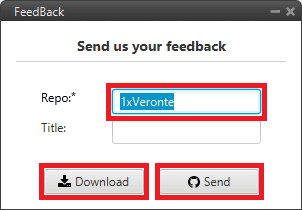
Feedback
These are the different functions of BCS control station. Each option will be explained in detail in the next sections.
Icon |
Item |
Description |
|---|---|---|
|
Introduce BCS information |
|
|
Configure I/O connections on BCS |
|
|
Configure parameter sensors |
|
|
Configure external sensors/devices and I/O signals |
|
|
Introduce Phases, Modes and Arcade axis configuration |
|
|
Configure automatic actions on event detection (go home, change phase…) |
|
|
Configure alternative communication channels, statistics and routing |
|
|
Cusomize transmitter configuration |
|
|
Customize algorithms executed by BCS |
|
|
Configure any connected devices: servo, radio, camera… |
|
|
Customize traffic: log, telemetry… |
|
|
Customize variable names |
|
|
Configure parameters for hardware simulation |
|
|
Customize checklist, block user control in PDI configuration and safety bits |