Troubleshooting
Communication lost with intenal Digi radio
Most of the time, the communication between BCS and Digi radio is lost due to a change in its baudrate.
In BCS PDI Builder it is set to 115200 by default, however, in Digi radios the factory default baudrate at reset is 9600.
To recover communication, try changing the baudrate on one of them to match.
Go to Communications \(\rightarrow\) Veronte LOS section.
Set the Baudrate to 9600.
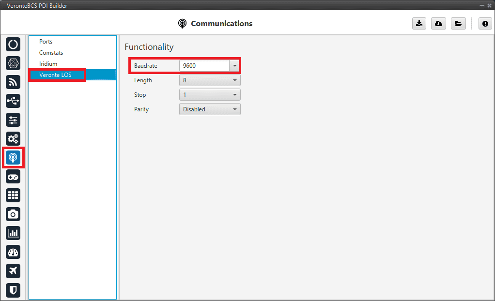
Veronte LOS baudrate
Check the steps described in the Digi internal radio -> Integration examples section to see if the module is now detected in XCTU software.
Then, if desired, the user can change the radio baudrate to 115200 and after that also change it for Veronte BCS.
Debug serial messages transmission
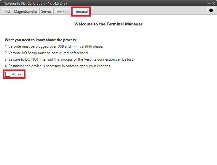
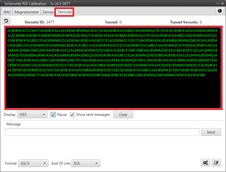
To check that the transmission of serial messages is being carried out correctly, the user can view what is being sent in the 1x PDI Calibration software hyperterminal. To do this:
In BCS PDI Builder
Go to Input/Output \(\rightarrow\) I/O Setup.
Connect the RS custom message producer (where the message is configured) to a Tunnel with App2 address. In this case the message is configured in the RS custom message 1 producer.
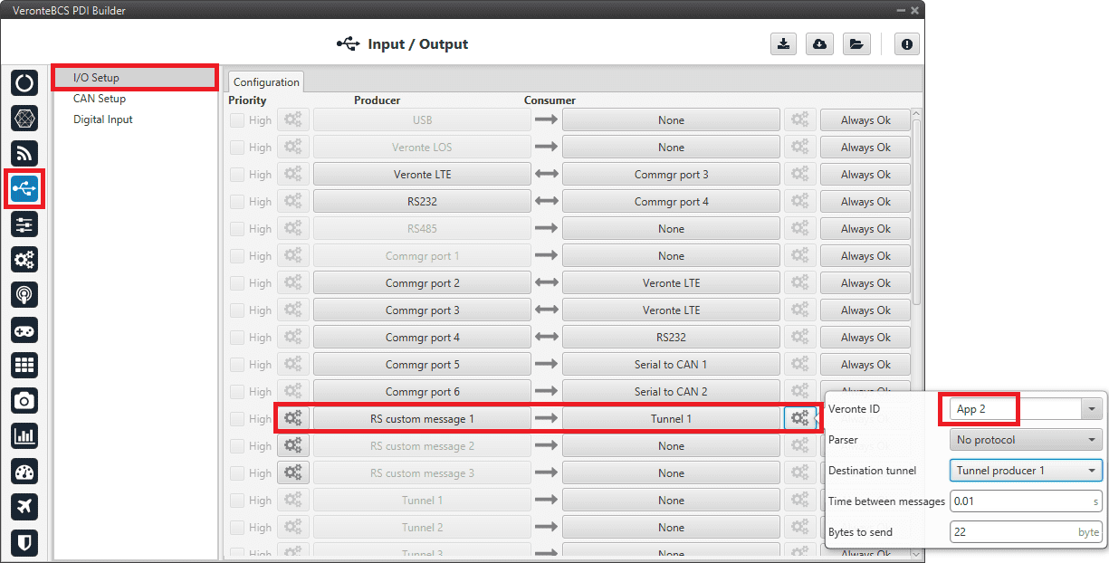
RS cutom message \(\rightarrow\) Tunnel
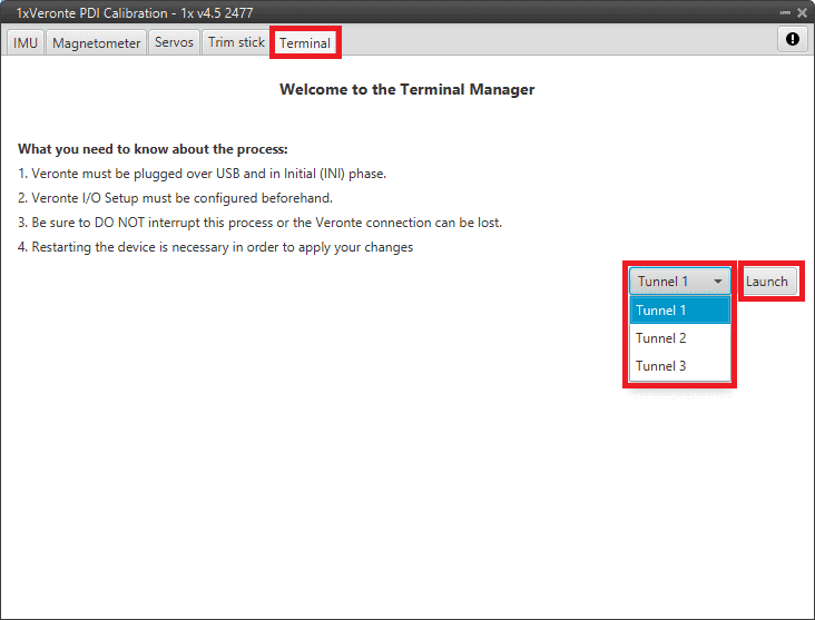
In 1x PDI Calibration
Maintenance mode
The user can simply enter maintenance mode via BCS PDI Builder by clicking on the “Normal mode” button in the initial menu. In addition, exiting maitenance mode is the same process.
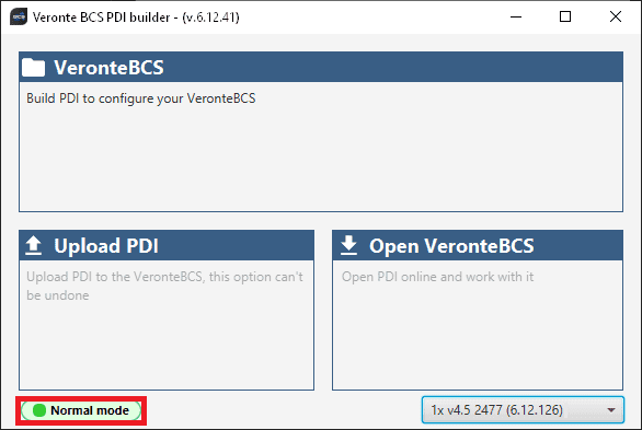
Enter/Exit maintenance mode
Maintenance mode (loaded with errors)
The following error message may appear when trying to save a change or import a configuration.
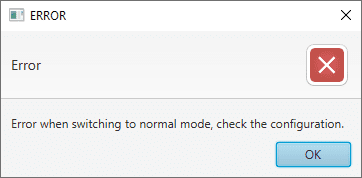
Error message
Therefore, BCS will be in ‘Maintenance mode (loaded with errors)’:
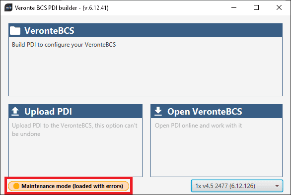
Maintenance mode (loaded with errors)
To check what the source of the problem is, the user can consult the Veronte Ops Platform panel, which will show which PDI Error it is. For more information on this panel, see Platform panel section of the Veronte Ops user manual.
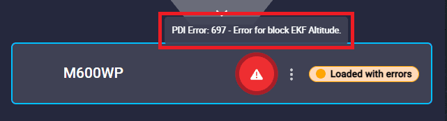
PDI Error - Veronte Ops
Then, it is possible to access the BCS configuration to fix this error.
In addition, a list of all PDI Errors can be accessed in the List of PDI errors section of the 1x Software Manual.
Radios paired but 1x air unit not showing
If the radios of 1x (air unit) and BCS (ground unit), are paired but the air unit does not appear connected in Veronte Link, check the Ports configuration on the BCS ground unit. To do this:
Go to Communications \(\rightarrow\) Ports section. It should be similar to the configuration shown in the figure below:
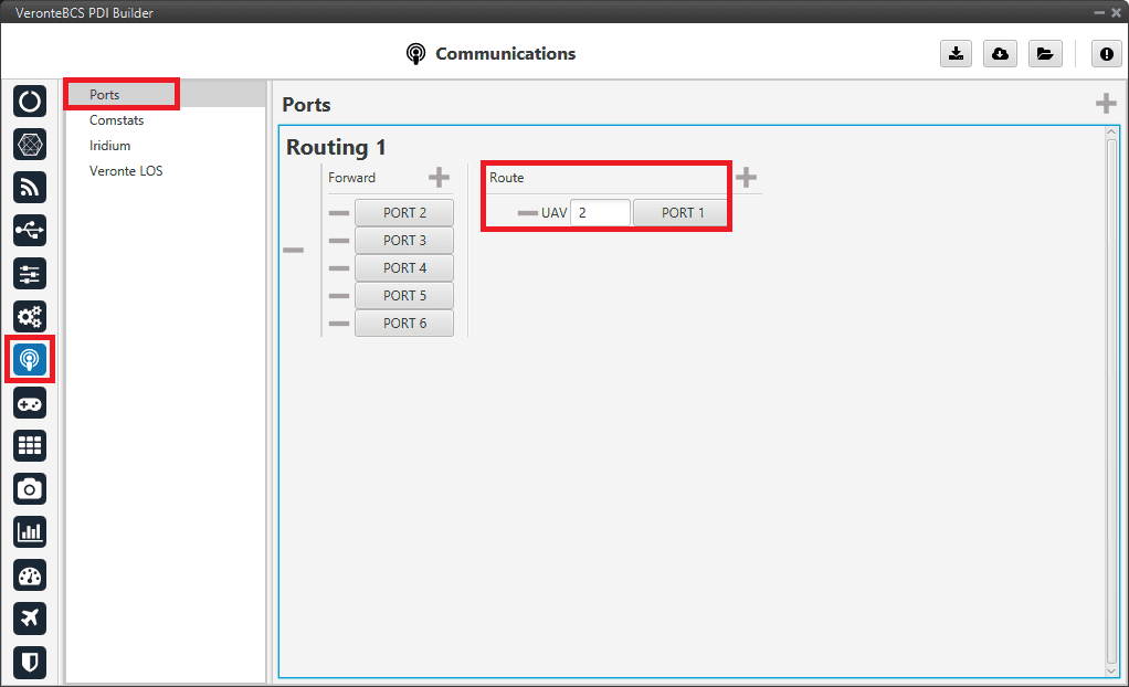
BCS (ground unit) - Ports configuration
Reduce GNC Task frequency
400 Hz is the maximum possible frequency, but it can only be used in simple configurations, in other cases it is advisable to reduce it to 250-300 Hz.
To find out if the frequency needs to be reduced in the user configuration, check the GNC Task Average CPU Ratio variable.
For correct operation, this variable should be at approximately 60-70%. If it reports a higher value, the frequency must be lowered.