 Sensors
RPM
BCS can measure RPMs by measuring up to 6 input sources:
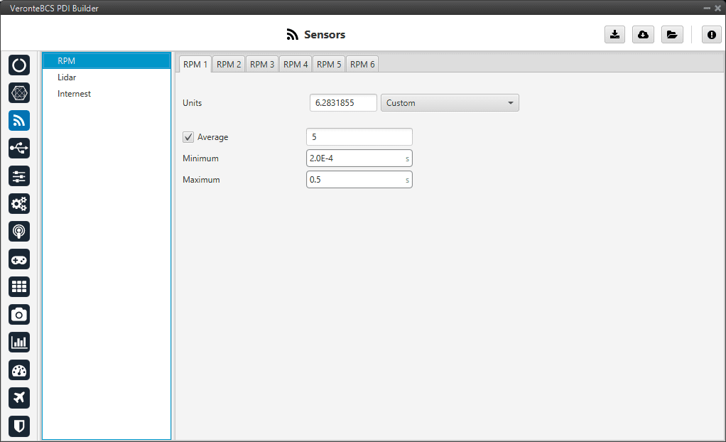
RPM menu
Units: Sensor conversion factor. It can be Custom, Radians per pulse or Pulse per cycle.
Average: Filter to prevent voltaje spikes. The readout of the pulse can be filtered as an average output. The amount of measurements to do the average needs to be specified.
Minimum: Here the minimum expected pulse period needs to be specified. This will discard spurius pulses (e.g. induced by EMI) which are smaller than this minimum pulse.
Maximum: This is the maximum period of time allowed without capturing. If no incoming pulse is received for more than this time, the output RPMs will be 0.
Lidar
The I2C bus allows the connection of several devices with different addresses to the same line via master-slave communication. At this moment, BCS supports the following Lidar devices:
Garmin LIDAR-Lite v3: Optical distance measurement sensor with a range from 5 cm to 40 m.
SF11 Lidar: Long range laser altimeter. Supported SF11/B and SF11/C with a range from 0 to 50 m and 0.2 m to 120 m respectively.
SF20 Lidar: OEM laser altimeter module. Supported SF20/C with a range from 0.2 m to 100 m.
BCS allows up to 5 lidar devices to be connected to the system at the same time. The configuration menu can be seen below:
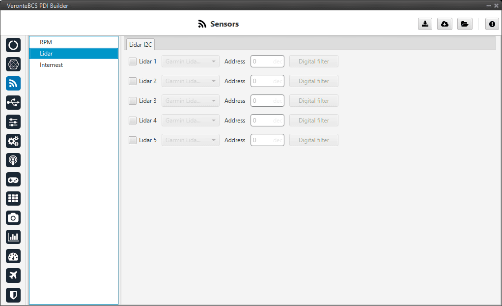
Lidar devices
After enabling the needed number of lidar devices, configurable parameters are:
Type of lidar.
Address: With an accepted value between 16 and 239, this is the origin address from the lidar being configured.
Digital filter: Enables a low pass filter which its cutoff frequency is configured manually, allowing the user to input any desired value in Hz. It is a software filter.
Warning
I2C address will be different for different devices make sure to define it properly by checking the manufacturer documentation.
Note
The lidar number (lidar 1/5) needs to be kept in order to properly configure the altimeter later.
Internest
An ultrasound sensor computes BCS position by measuring the time that signal sent out takes to return. The following panel together with Relative position sensor block allows the user to configure an Internest system with BCS.
This menu allows the user to choose the version of Internest to be used, its range and the rotation matrix:
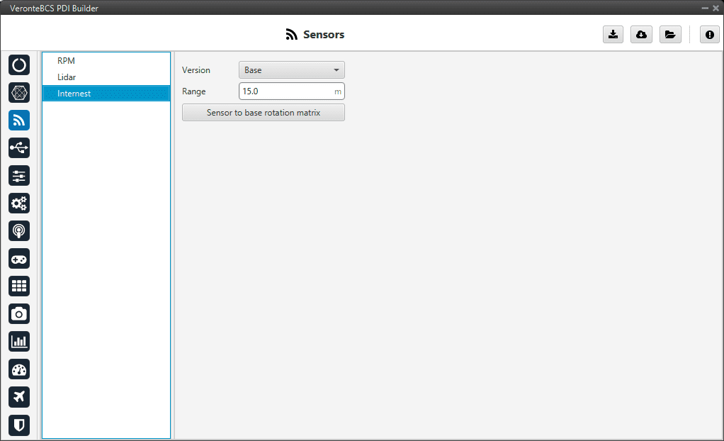
Internest menu
Version: Users must choose the version of the Internest system, the available options are Base and Explore.
Range: Defines the distance at which Internest values will start to be valid.
Sensor to base: Matrix to rotate the system to match the BCS coordinate system.
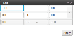
Internest - Rotation matrix