 Input/Output
I/O Setup
In this panel the user can stablish the relationship between a determined signal with a I/O port. This allows users to configure external sensors, messages between BCS units (Tunnel) and custom messages.
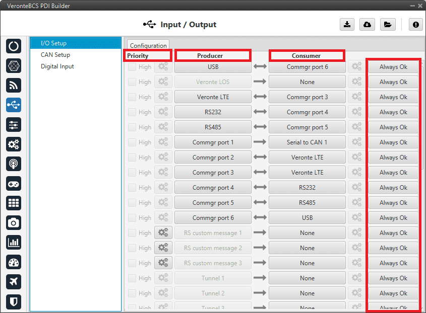
I/O Setup menu
Priority: Connections between I/O ports can be marked with high priority with this checkbox. If enabled, they will run at high frequency: 1000 Hz.
Producer: Functions for creating and sending messages.
Consumer: Functions for receiving and parsing messages
Bit: This assigns each connection a bit in a way that allows this connection to be activated/deactivated depending on the status of the selected bit.
By default, the ‘Always Ok’ bit is set to all connections so that they are always active.
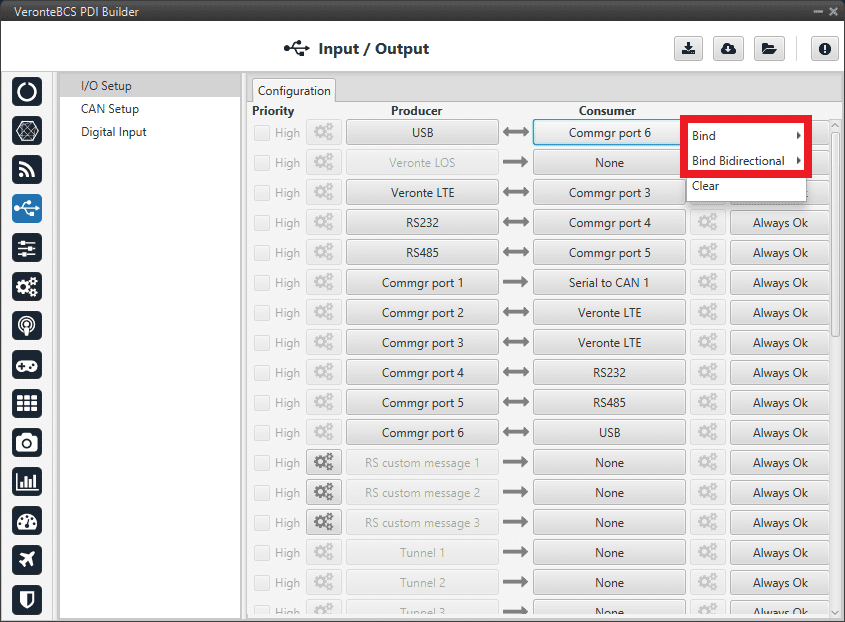
I/O Setup consumer options
Firstly, users have to configure the Producer selecting the I/O port or information to use. Later, users have to configure the Consumer by clicking on an element, a new window will be displayed to select an item. The relationship between them can be unidirectional (Bind \(\rightarrow\)) or bidirectional (Bind Bidirectional \(\leftrightarrow\)), the last enables a port to receive or send information.
The following I/O ports are available:
Field |
Description |
|---|---|
USB |
USB Port |
Veronte LOS |
Radio |
Veronte LTE |
4G Connection |
Veronte LTE Auxiliary |
Reserved port |
RS232 |
Serial Port 232 |
RS485 |
Serial Port 485 |
Commgr port |
COM Manager ports send and receive VCP messages. This is the protocol used by Veronte products to communicate. For more information on VCP, read the VCP user manual |
Tunnel |
Creates a bidirectional brigde between two devices, see Tunnel |
RS Custom Message |
This allows user to send/receive a serial custom message, see Serial Custom Messages |
GPS RTCM |
This allows the user to send/receive RTK information from GND unit to AIR unit |
Iridium |
Iridium communication, see Iridium section |
Y Splitter |
Used to split a signal into 2 |
NMEA Parser |
NMEA 0183 messages parser, see NMEA Parser |
Unescape port |
This allows user to reconstruct a byte stream with an escape logic, see Unescape port |
CAN to serial / Serial to CAN |
Serial to CAN sends serial streams over a CAN Bus / CAN to serial undoes the transformation ‘Serial to CAN’ |
CAN wrapper / CAN unwrapper |
CAN wrapper sends CAN streams over a serial Bus / CAN unwrapper undoes this transformation |
External ultrasound |
External ultrasound sensor, see Internest section |
More information about some elements can be found in the following sections.
Tunnel
It is possible to configure a Tunnel which is a bidirectional bridge between BCS units that communicate to each other sharing information about an external device connected to the Serial or Digital port.
Let’s consider the following image.
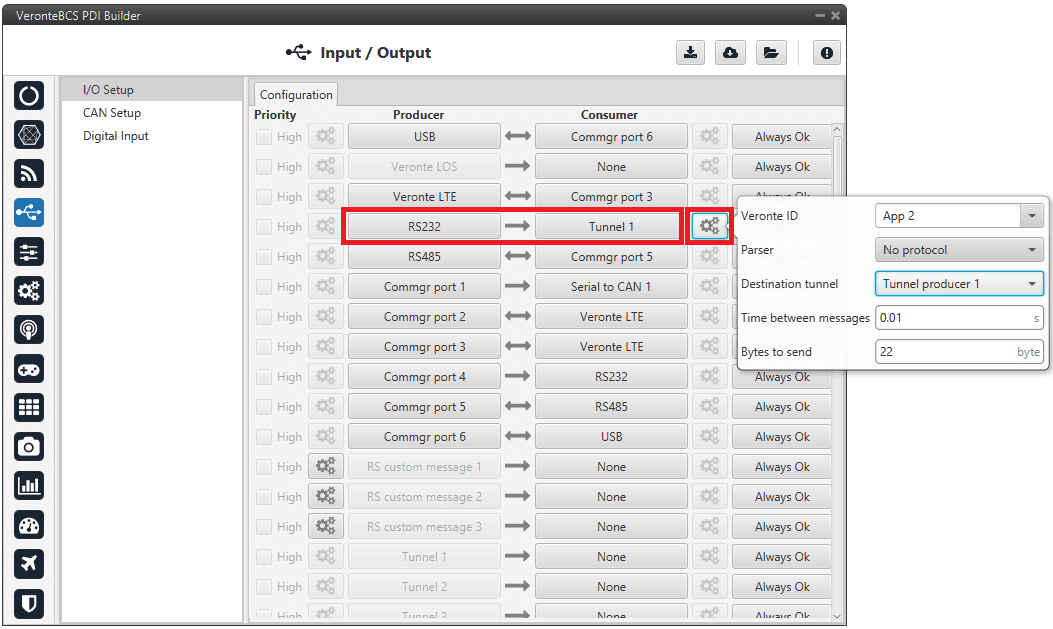
Tunnel configuration
In the image above there is a device connected to the RS232 (Producer) and there is a Tunnel (Consumer) which sends that information to Veronte Ops. In that case the Producer will be Tunnel and Consumer will be the port or destination tunnel where the device is connected.
The options available when configuring Tunnel as Consumer are:
Veronte ID: Select the address that will receive the information.
App 2: Veronte Ops address.
Broadcast: All units on the network. Select this option for a generic configuration.
Veronte v4.X XXXX: Address of a specific unit, it can be a 1x, a 4x, a CEX, etc.
Parser: The user can choose protocol to parse message data. The options available are:
No protocol
RTCM3
CANserial
Destination tunnel: Number of port is used to avoid mistakes and identify a Tunnel when using more than one, Tunnel 1, 2 and 3 are available.
Time between messages.
Bytes to send: Sets the message size to send.
When configuring Tunnel as Producer (i.e. on the unit that receives the information), no configuration is required. It is only necessary to connect it to a Consumer, usually to a serial port.
Serial Custom Messages
Warning
BCS autopilot has a serial limitation of 64 vectors (fieldset) per Custom.
In addition, there is a limit shared with all Customs, including CAN Custom Messages:
Maximum number of vectors (fieldset): 104
Maximum number of fields: 2000
It is possible to configure the messages sent/received through the serial port and its conversion to system variables by selecting the option RS Custom message and configuring the I/O port.
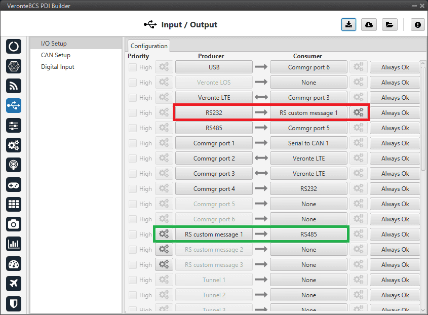
Serial Custom Messages
In the image above can be seen two possible configurations using a RS Custom Message. The ‘red’ one is configured to receive a determined message from a RS-232 serial port and the ‘green’ is used to send a RS Custom Message through a RS-485 serial port. It is also possible to use the same RS Custom Message for both tasks if the bidirectional relationship is selected (the arrow indicates this (Bind Bidirectional \(\leftrightarrow\))).
To configure a RS Custom message, the user must follow the next steps:
Press the configuration button (
 icon) and another window will be displayed. In this window press the “+” icon to add a custom message, the user can choose between System variables, ADSB Vehicle or External Sensor.
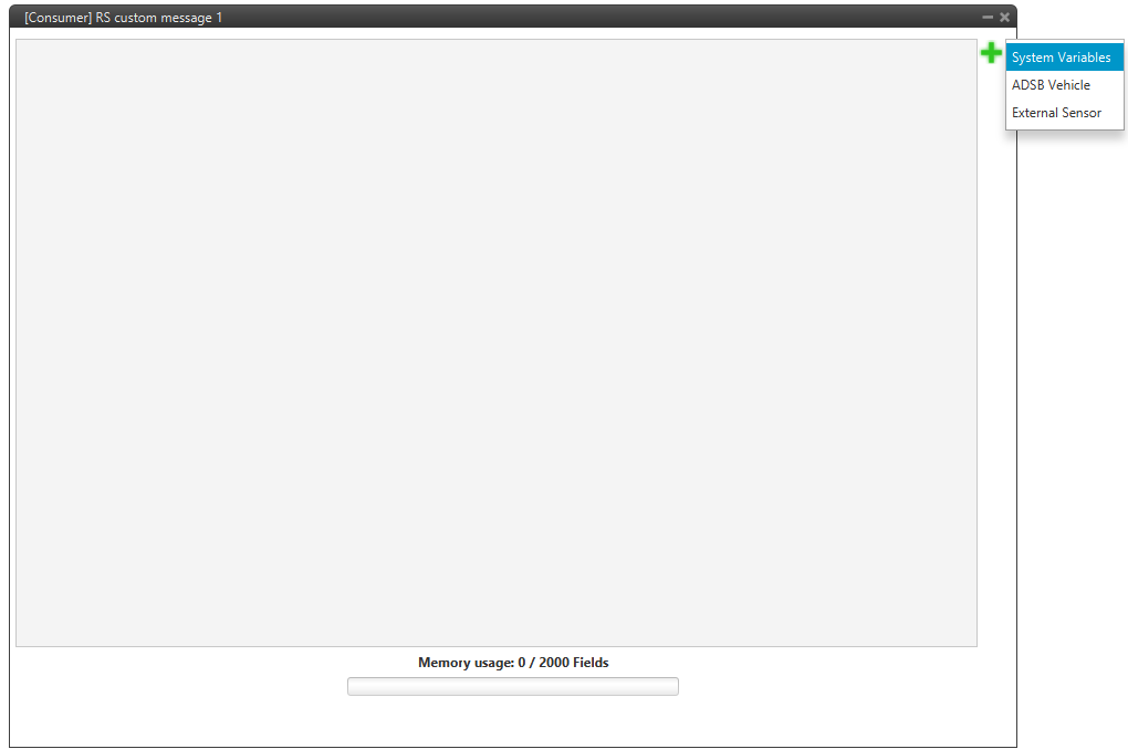
Serial Custom Message configuration
Note
The difference between choosing System Variables, ADSB Vehicle or External Sensor is that when the user selects Variable as the custom message type, only system variables will appear when System Variables is selected, only ADSB variables when ADSB Vehicle is selected and only variables related to external sensors if External Sensor is selected.
When it is already added, the following options are available to configure a custom message:
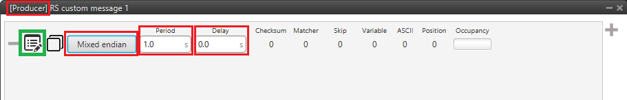
Producer RS Custom Message configuration
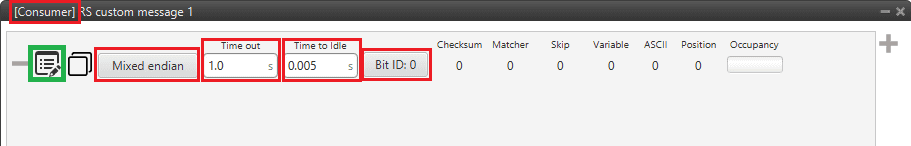
Consumer RS Custom Message configuration
Endianness: Depending on the order in which the device issue the message, it is possible to select:
Big endian: Set the value from left to right.
Little endian: Set the value from right to left.
Mixed endian: Some devices use this format. If users need to configure it, please contact the support team (create a ticket in the customer’s Joint Collaboration Framework; for more information, see Tickets section of the JCF manual).
Period/Time out: This option has a dual role depending on if it is used to transmit or receive data.
Period - Producer: It is the inverse of the send frequency.
Time out - Consumer: This is the threshold time between receptions to consider that the message is not being received correctly.
Delay/Time to Idle: This option has a dual role depending on if it is used to transmit or receive data.
Delay - Producer: It is a delay applied before sending the message. This serves to send messages with the same period without overloading the Serial bus.
Time to Idle - Consumer: This is the time that BCS waits before discarding partially parsed bytes.
Bit ID: This option is only available when a message is configured as Consumer. The user bit selected in Bit ID box will be true if the message is being received correctly.
Warning
Pay attention that the user bit selected in Bit ID is not in use for another task.
To create the structure of the message, click on the edit message button (
 icon) and then press the “+” icon to add fields to it. The following type of messages are available to configure a structure: Variable, Checksum, Matcher, Skip, Parse ASCII and Position. The configuration of each structure is covered in Custom Messages section.
Warning
Before configuring any message, user has to know the structure it has to have according to the device that is connected to the port. Each device may have a different message structure when it sends or receives information.
To check serial messages transmission, see the Debug serial messages transmission -> Troubleshooting section of this manual.
NMEA Parser
NMEA Parser is another way to add an axternal GNSS device. This consumer allows to receive NMEA 0183 messages and parses them directly. The NMEA Parser configuration menu includes the following parameters:
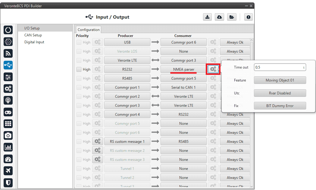
NMEA Parser configuration
Time out: Defines the period of incoming information from the external system.
Feature: Variable extracted from the message defining the GNSS position. Usually Moving Object variables are used in BCS PDI Builder.
Utc: Variable extracted from the message defining the UTC.
Fix: Data provided by the external device which is important to know the status of the positioning.
Once the NMEA message has been parsed, the variables used for Fix and Feature can be selected in the GPS External configuration of the GNSS block as Fix Bit and GPS Position.
Unescape port
To understand what unescape is, the user must first understand what an escape byte is.
Let’s consider that there is a protocol that defines a ‘Flag’ as the start and end byte of the frame. In case the flag or an escape value appears in the frame data, and in order not to misinterpreted the message, an escape byte or the same value repeated will be added before them so that, at the time of parsing, it will be reconstructed with the original byte.
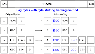
Escape byte
In BCS PDI Builder, an Unescape port has been implemented to allows to reconstruct a byte stream with an escape logic.
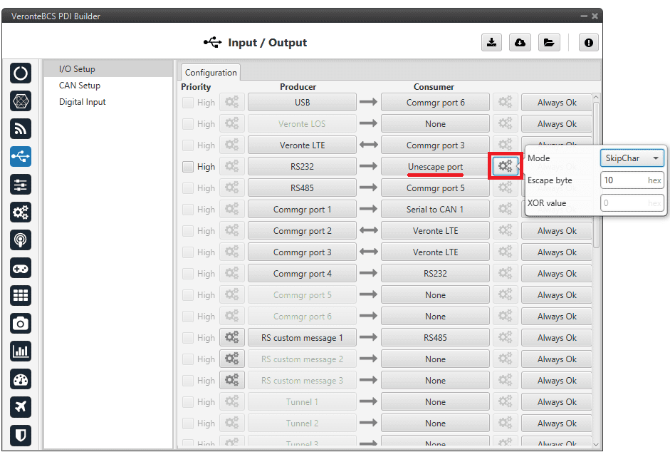
Unescape port configuration
Two modes of escapes are supported:
SkipChar: The unfolding of the value to be escaped, the byte to escape has been repeated in the message.
SkipAndXOR: In this case, the escape byte is entered first and then the value to escape (i.e. the value to escape XOR escape byte).
In addition to this, two more options are available in this pop-up window:
Escape byte: Escape byte added.
XOR value: Only available when ‘SkipAndXOR’option is selected.
CAN Setup
A CAN (Controller Area Network) Bus is a robust vehicle bus standard widely used in the aviation sector. BCS is fitted with two CAN buses that can be configured independently.
The structure of a CAN message can be seen in the following image:
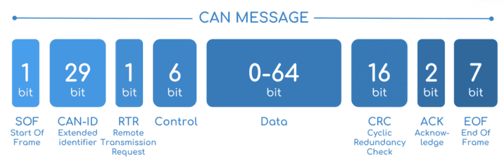
CAN message structure
Only the ID is introduced in the system, the rest of the message layout is already coded. The data field is the one build by the user to send, and parsed when received.
The baud rate of both CAN buses can be configured in the Mailboxes section.
The steps to be followed from the moment a CAN message arrives at or is sent from the BCS are described in the CAN communication -> Integration examples section.
Configuration
This menu allows the configuration of communications between different devices.
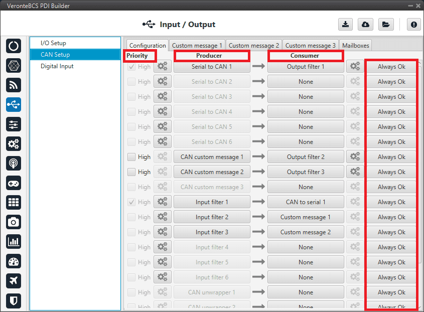
CAN configuration section
In this menu, the user can find the same ‘columns’ (Priority, Producer, Consumer and Bit) as in the I/O Setup menu.
Warning
In CAN, in Low state the specified period is not guaranteed but in High state it is.
However, only those messages that are critical for external devices should be set as high priority, as this may disrupt the proper functioning of Veronte BCS.
On the one hand, BCS has the producers shown below:
Serial to CAN: Serial messages over CAN output, it has to be connected to I/O Setup consumer. It can be configured in the configuration button (
icon), a pop-up window will appear: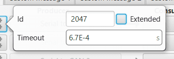
Serial to CAN configuration
Id: CAN Id must be set and it is used to identify messages. The value set has to be decimal format.
Extended: If enabled, the frame format will be this, ‘Extended’, i.e. with a 29-bit identifier. Otherwise, the frame format ‘Standard’ (11-bit identifier) is set by default.
Time out: This is the threshold time between receptions to consider that it is not being received correctly.
CAN custom message: CAN custom messages transmission. They are configured in the next section, see Custom Messages.
Input filter: CAN input filters. Those CAN messages received in one filter can no longer be received in subsequent filters. Input filter must be configured in the configuration button (
icon), a pop-up window will appear: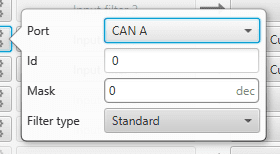
Input filter configuration
Port: It is required to configure the CAN bus from which it listens, the user can choose between CAN A, CAN B or BOTH.
Id: CAN Id must be set and it is used to identify messages. The value set has to be decimal format.
Mask: Here a CAN Id mask can be set to filter messages. The mask defines the bits that should match.
Filter type: The options available are Standard, Extended and Both.
Attention
Make sure that the mask is set properly to be able to receive the desired CAN messages.
CAN unwrapper: This undoes the ‘CAN wrapper’ action, it has to be connected to I/O Setup consumer.
CAN GPIO remote: CAN messages to GPIO peripherals such as CEX. It can be configured in the configuration button (
icon), a pop-up window will appear: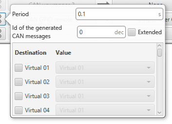
CAN GPIO remote configuration
Period: It is the period of sending messages.
Id of the generated CAN message: CAN Id must be set and it is used to identify messages. The value set has to be decimal format.
Extended: If enabled, the frame format will be this, ‘Extended’, i.e. with a 29-bit identifier. Otherwise, the frame format ‘Standard’ (11-bit identifier) is set by default.
Destination: Here the user select the destination CEX pins.
Value: The user must select the BCS pin to be connected to the CEX pin.
CAN 4x: CAN message transmission already configured for correct communication between the 1x autopilots within the Veronte Autopilot 4x. If the user has any questions, please contact the support team following the Joint Collaboration Framework.
On the other hand, the consumers are the following:
CAN to serial: This undoes the ‘Serial to CAN’ action, it has to be connected to I/O Setup producer.
Custom message: CAN custom messages reception. They are configured in the next section, see Custom Messages.
Output filter: CAN output filters. The user can choose between CAN A, CAN B or BOTH in the configuration button (
icon).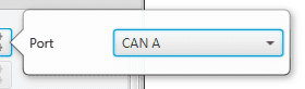
Output filter configuration
CAN wrapper: CAN messages over serial output, it has to be connected to I/O Setup producer.
CAN 4x: CAN message reception already configured for correct communication between the 1x autopilots within the Veronte Autopilot 4x. If the user has any questions, please contact the support team following the Joint Collaboration Framework.
Custom Messages
In the custom message tabs (there are 3 available), the user chooses the variables to be sent/received over the CAN buses. The following elements can be configured:
TX Ini: Used to configure transmitted messages that are only sent once at the beginning of the operation (sent when the autopilot boots up). They can be used to initialize some devices.
TX: Used to configure transmitted messages.
RX: Used to configure the reception messages (where they are stored).
Warning
The maximum capacity of a CAN message is 64 bits (8 bytes), so to send more information it must be divided into several messages.
BCS has a CAN limitation of 40 TX messages per Custom, 40 TX Ini messages per Custom and 80 RX messages per Custom.
In addition, there is a limit shared with all Customs, including RS Custom Messages:
Maximum number of vectors (fieldset): 104
Maximum number of fields: 2000
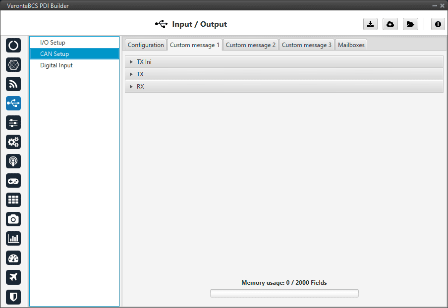
CAN Custom Message section
Since this section works in a similar way to the CAN Custom Message configuration in the 1x PDI Builder software, the explanation to configure the telemetry messages via CAN can be found in the CAN Setup -> Input/Output section of the 1x PDI Builder user manual.
Mailboxes
Here the user can modify the mailboxes from the selected CAN bus (CAN A or CAN B).
When BCS is going to receive data on the CAN Bus, it is mandatory to configure a certain number of mailboxes. However, it is also necessary to have at least 1 mailbox for transmission (TX).
In order to add a mailbox, press the “+” icon.
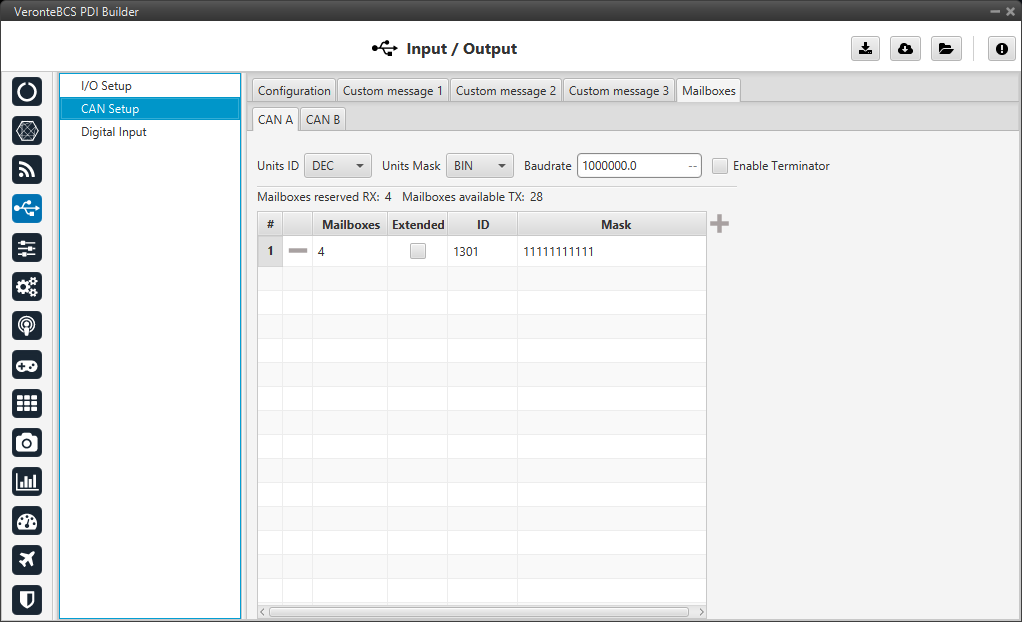
Mailboxes section
More information about Mailboxes can be found in the Mailboxes section of the 1x PDI Builder user manual.
Digital Input
GPIO pins can work as Digital Input or Output as well as PWM. In order to configure some custom sensors such as a Stick PPM, Pulse sensor or RPM sensor pins are reserved, which correspond to pins 55-58. These pins can also be used as Digital I/O.
Sensors using a Digital Input are configured in this menu.
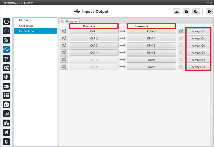
Digital Input section
In addition, in this menu the user can also find the same ‘columns’ (Producer, Consumer and Bit) as in the I/O Setup menu.
The process to configure a device can be done as follows:
Select and configure a Producer. There are 6 possible producers: CAP 1 - 6.
Press on the configuration button (
icon) and a new pop-up window will show.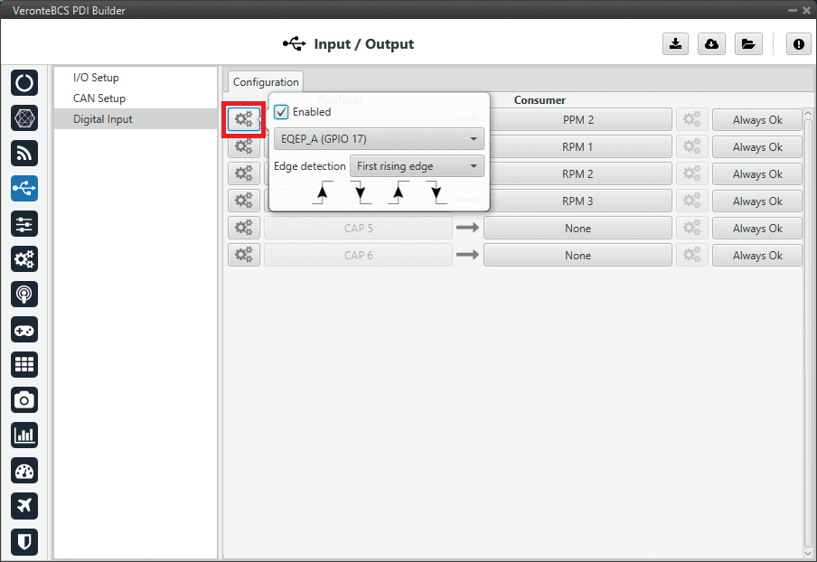
Digital Input - Producer
In the pop-up window, users can check:
That this producer is enabled.
Which pin this CAP is associated and, therefore, to which device is connected. It is possible to select these pins. Pins available are GPIO 1 to 16, and EQEP A, B, S and I. When using the harness provided by Embention the transmitter Digital Input is connected to the pin 55 (EQEP_A) with pin 49 as Ground.
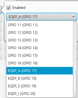
Digital Input - CAP
How the pulses are read and transformed into a digital signal (how they are processed). That can be configured with the Edge detection option.
By clicking on the drop-down menu, the following options can be selected:
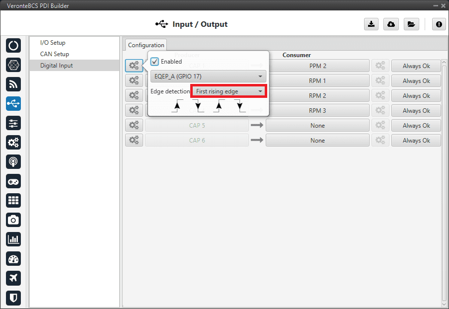
Digital Input - Edge detection option
First rising edge: With this option, when the rise of the pulse is detected, the data will start to be stored. Recommended when consumer is PPM or Pulse.
First falling edge: With this option, when the fall of the pulse is detected, the data will start to be stored.
Note
By clicking on the arrows, it can also be configured in a specific way.
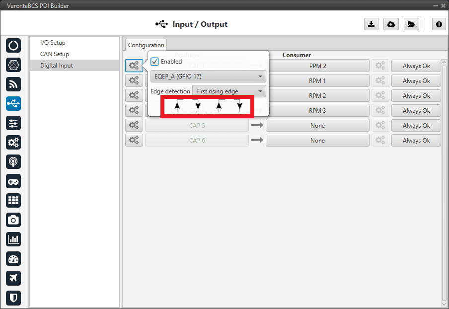
Digital Input - Edge detection option
Click on the Bind button to select the type of Consumer, it is possible to choose among a PPM 1-4 (Stick PPM), RPM 1-6 (RPM sensor) or Pulse 1-4 (Pulse).
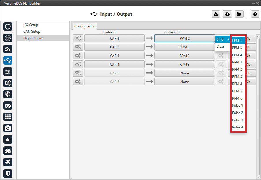
Digital Input - Consumer
PPM 1-4 selected: PPM is configured in the Stick menu.
RPM 1-6 selected: The variables in which the information read here is stored are ‘RPM 1-6’. For more information on the configuration of RPM, see the RPM section.
Pulse 1-4 selected: The variables in which the information read here is stored are ‘Captured pulse 1-4’. It is possible to configure it clicking on the configuration button (
icon):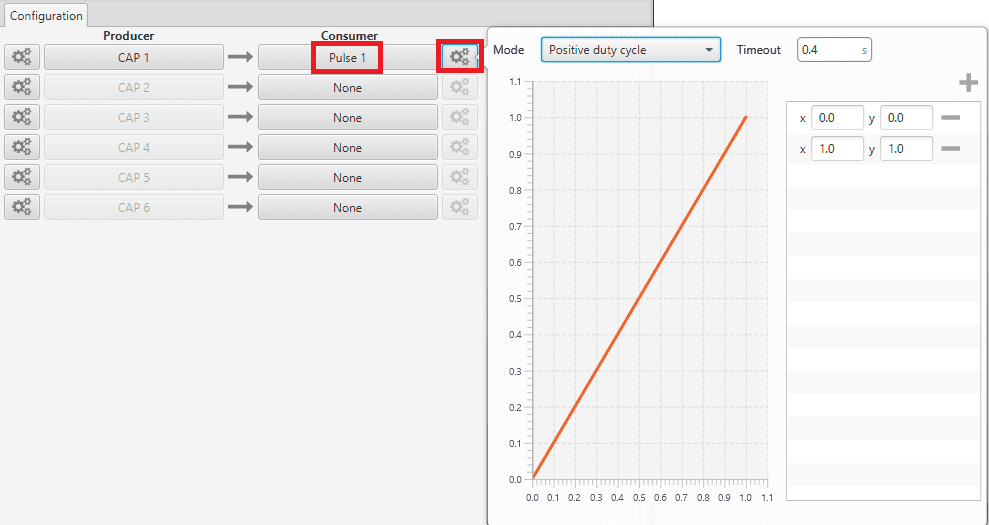
Digital Input - Pulse
In the pop-up window, users will find the following options for configuration:
Mode:
Positive pulse duration: The period of the pulse is obtained. It takes the time in ‘High’ state.
Negative pulse duration: The period of the pulse is obtained. It takes the time in ‘Low’ state.
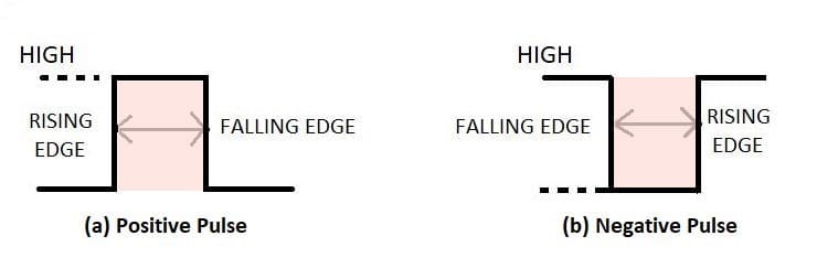
Positive/Negative pulse duration
Positive duty cycle: The duty cycle. It takes the time in ‘High’ state.
Negative duty cycle: The duty cycle. It takes the time in ‘Low’ state.
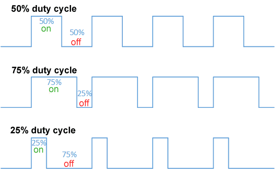
Positive/Negative duty cycle
Time out: This defines the time to consider that no signal is received.
Function: Here the user can customise a function to handle the values. Normally, a function is set with the points [0,0] and [1,1], so no transformation is applied, input = output. However, the user can configure it as desired.
Example
Let’s imagine that First rising edge has been selected as the edge detection option in Producer and the pulse that BCS has to read is a square signal with a period of 2 seconds and a duty cycle of 25% (see image below).

Signal generated
On the other hand, if Positive pulse duration is selected as Consumer and it is configured as in the previous image (Digital Input - Pulse), the value obtained in the variable Captured pulse (Captured pulse 1 in the following example) will be 0.50s, this is because it is the period of the “Positive pulse” of that pulse.
However, if Positive duty cycle is selected as Consumer, the value obtained in the variable Captured pulse (Captured pulse 2 in the following example) will be 0.25, this is because it is the positive duty cycle of that pulse.
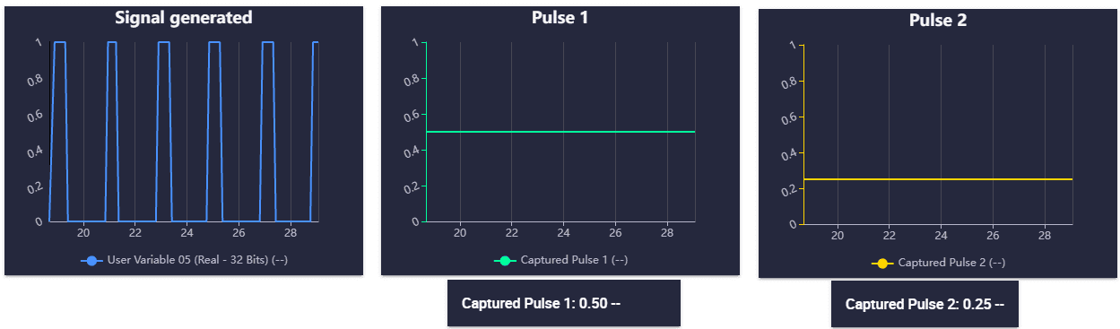
Digital Input example