Hardware Installation
Mechanical assembly
BCS is manufactured using an anodized aluminium enclosure with enhanced EMI shielding and IP protection. A high reliability connector is also provided in this version. The total weight of standard version is 190g.
Dimensions
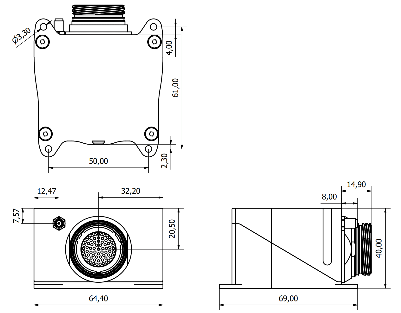
Veronte BCS dimensions (mm)
M3 screws are recommended for mounting. In saline environments such as coastal and oceanic, the screw material must be stainless steel.
Antenna Integration
The system uses different kinds of antennas to operate that must be installed on the airframe. Here you can find some advice for obtaining the best performance and for avoiding antenna interferences.
Antenna Installation
Maximize separation between antennas as much as possible.
Keep them far away from alternators or other interference generators.
Always isolate antenna ground panel.
Make sure the antenna is securely mounted.
Always use high-quality RF wires minimising the wire length.
Always follow the antenna manufacturer manual.
SSMA connections shall be tightened applying 1 Nm of torque
For all-weather aircraft, insert SSMA lightning protectors.
Electrical
Power
BCS can use unregulated DC (6.5V to 36V).
LiPo batteries between 2S and 8S can be used without regulation needs. Remaining battery level can be controlled by the internal voltage sensor and by configuring the voltage warnings by software.
For higher voltage installations, voltage regulators must be used. For dimensioning voltage regulators take into account that a blocked servo can activate regulator thermal protection.
Warning
Power out of range can cause irreversible damage to the system. Please read carefully the manual before powering the system.
Pinout
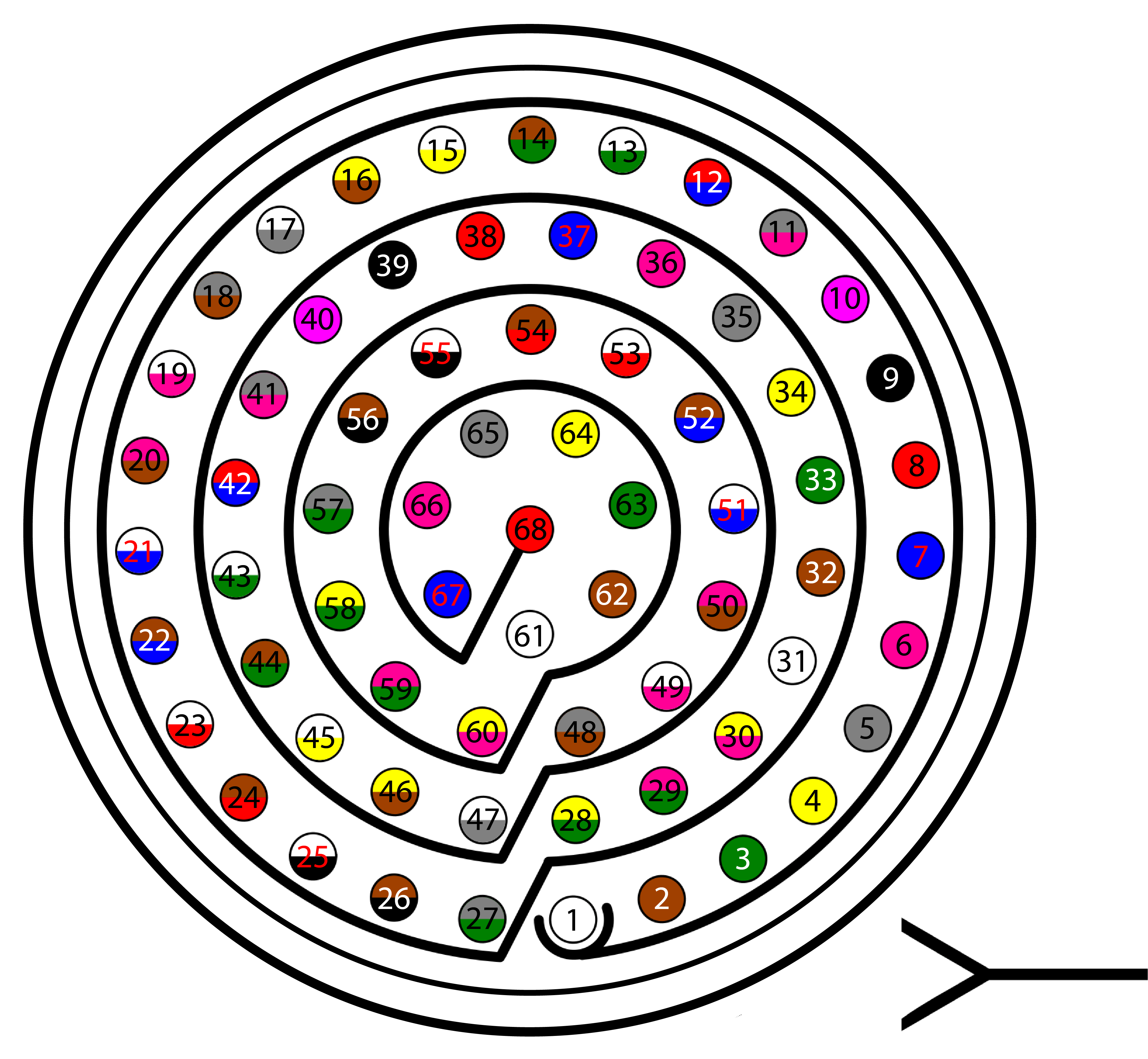
68 pin connector for BCS (frontal view)
Pin |
Signal |
Type |
Comments |
|---|---|---|---|
1 |
I/O1 |
I/O |
Pins for PWM or digital I/O signals (0-3.3V). Protected against ESD and short circuit. Warning Each pin withstands a maximum current of 1.65 mA. |
2 |
I/O2 |
||
3 |
I/O3 |
||
4 |
I/O4 |
||
5 |
I/O5 |
||
6 |
I/O6 |
||
7 |
I/O7 |
||
8 |
I/O8 |
||
9 |
GND |
GROUND |
Ground signal for actuators 1-8 |
10 |
I/O9 |
I/O |
Pins for PWM or digital I/O signals (0-3.3V). Protected against ESD and short circuit. Warning Each pin withstands a maximum current of 1.65 mA. |
11 |
I/O10 |
||
12 |
I/O11 |
||
13 |
I/O12 |
||
14 |
I/O13 |
||
15 |
I/O14 |
||
16 |
I/O15 |
||
17 |
I/O16 |
||
18 |
GND |
GROUND |
Ground signal for actuators 9-16 |
19 |
RS 232 TX |
Output |
RS 232 Output (-13.2V to 13.2V Max, -5.4V to 5.4V Typical). Protected against ESD and short circuit |
20 |
RS 232 RX |
Input |
RS 232 Input (-25V to 25V Max, -0.6V Low and 2.4V High Threshold). Protected against ESD and short circuit |
21 |
GND |
GROUND |
Ground signal for buses |
22 |
NO CONNECT |
||
23 |
|||
24 |
GND |
GROUND |
Ground signal for buses |
25 |
CanA P |
I/O |
CANbus interface, up to 1Mbps (2.3V Typical, 1.2V-2.3V Differential). Protected against ESD |
26 |
CanA N |
I/O |
Twisted pair with a 120 ohms Zo recommended (2.3V Typical, 1.2V-2.3V Differential). Protected against ESD |
27 |
4XV_WD |
I/O |
Reserved. Do not connect. |
28 |
CANB_P |
I/O |
CANbus interface. It supports data rates up to 1 Mbps. Protected against ESD |
29 |
CANB_N |
I/O |
Twisted pair with a 120 ohms Zo recommended. Protected against ESD |
30 |
GND |
GROUND |
Ground signal for buses |
31 |
I2C_CLK |
Output |
Clk line for I2C bus (0.3V to 3.3V). Protected against ESD and short circuit |
32 |
I2C_DATA |
I/O |
Data line for I2C bus (0.3V to 3.3V). Protected against ESD and short circuit |
33 |
GND |
GROUND |
Ground for 3.3V power supply |
34 |
3.3V |
POWER |
3.3V - 100mA power supply. Protected against ESD short circuit with 100mA resettable fuse |
35 |
GND |
GROUND |
Ground for 5V power supply |
36 |
5V |
POWER |
5V - 100mA power supply. Protected against ESD short circuit with 100mA resettable fuse |
37 |
GND |
GROUND |
Ground for analog signals |
38 |
NO CONNECT |
||
39 |
|||
40 |
|||
41 |
4XV_A |
I/O |
Reserved. Do not connect. |
42 |
NO CONNECT |
||
43 |
|||
44 |
4XV_B |
I/O |
Reserved. Do not connect. |
45 |
UARTA_TX |
Output |
Microcontroller UART |
46 |
UARTA_RX |
Input |
Microcontroller UART |
47 |
GND |
GROUND |
Ground signal comicro power supply |
48 |
NO CONNECT |
||
49 |
FTS3_OUT_MPU |
Output |
MPU alive voting signal, to use with 4xVeronte. It is a Square Wave at [100,125] Hz. Protected against ESD and short circuit |
50 |
OUT_RS485_P |
Output |
Non-inverted output from RS485 bus (-7V to 12V Max, -2.3V to 2.3V Typical). Protected against ESD and short circuit |
51 |
OUT_RS485_N |
Output |
Inverted output from RS485 bus (-7V to 12V Max, -2.3V to 2.3V Typical). Protected against ESD and short circuit |
52 |
IN_RS845_N |
Input |
Inverted input from RS485 bus (-7V to 12V Max, -2.3V to 2.3V Typical). Protected against ESD and short circuit |
53 |
IN_RS845_P |
Input |
Non-inverted output from RS485 bus (-7V to 12V Max, -2.3V to 2.3V Typical). Protected against ESD and short circuit |
54 |
RS-485_GND |
GND |
Ground for RS-485 bus |
55 |
EQEP_A |
I/O |
DIGITAL output / DIGITAL input / Encoder quadrature input A (0-3.3V). Protected against ESD and short circuit |
56 |
EQEP_B |
I/O |
DIGITAL output / DIGITAL input / Encoder quadrature input B (0-3.3V). Protected against ESD and short circuit WARNING!: Only use it as digital I/O with Veronte units of Hardware version 4.5 or lower |
57 |
EQEP_S |
I/O |
DIGITAL output / DIGITAL input / Encoder strobe input (0-3.3V). Protected against ESD and short circuit |
58 |
EQEP_I |
I/O |
DIGITAL output / DIGITAL input / Encoder index input A (0-3.3V). Protected against ESD and short circuit |
59 |
GND |
GROUND |
Ground for encoders |
60 |
V_USB_DP |
I/O |
Veronte USB data line. Protected against ESD |
61 |
V_USB_DN |
I/O |
Veronte USB data line. Protected against ESD |
62 |
USB_SHIELD |
GND |
USB cable shielding |
63 |
FTS_OUT_MPU |
Output |
Abort mission voting signal from MPU, to use with 4xVeronte. Bit Low (0V) if mission OK. High (3.3V) if mission wants to be terminated. Protected against ESD and short circuit |
64 |
FTS2_OUT_MPU |
Output |
Abort mission voting signal 2 from MPU, to use with 4xVeronte. Bit Low (0V) if mission OK. High (3.3V) if mission wants to be terminated. Protected against ESD and short circuit |
65 |
GND |
GROUND |
Veronte ground input |
66 |
GND |
GROUND |
Veronte ground input |
67 |
VCC |
POWER |
Veronte power supply (6.5V to 36V). Protected against ESD and reverse polarity. Warning Both pins are common. They MUST be connected to the same power supply. |
68 |
VCC |
POWER |
|
Warning
Remember!! All GND pins are common.
Connector colour code:
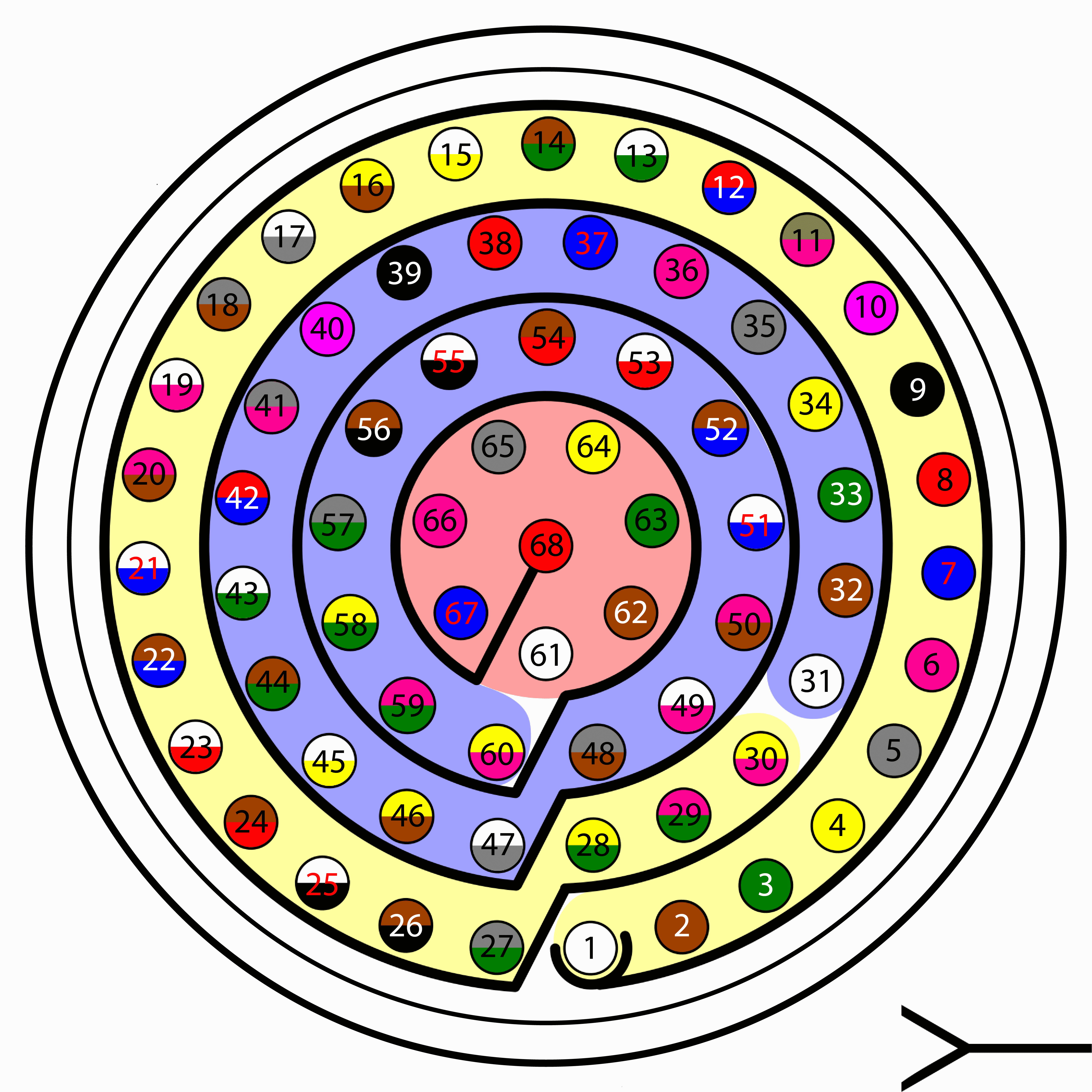
Connector HEW.LM.368.XLNP
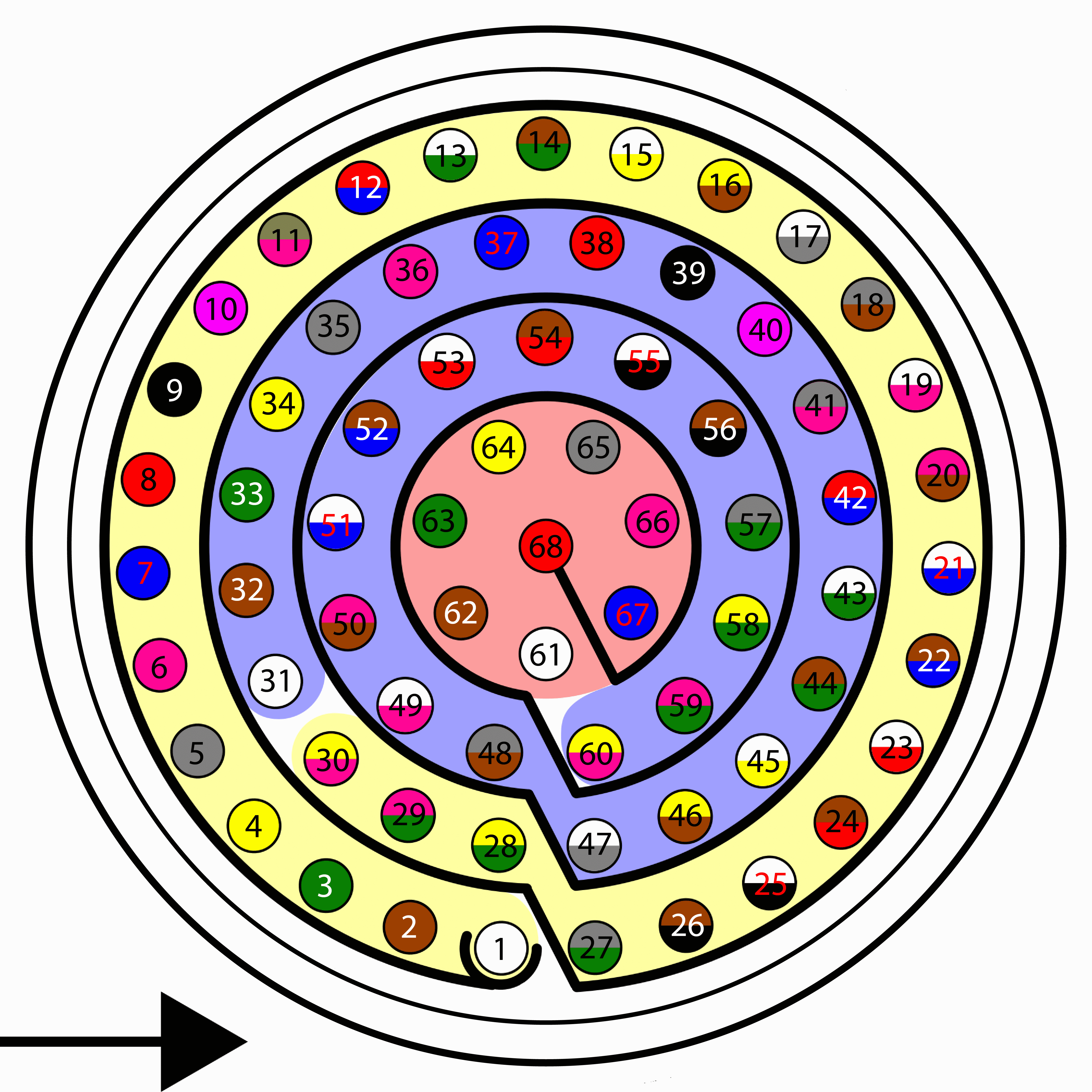
Harness plug
Warning
Check the pin number before connecting. The colour code is repeated 3 times due to the amount of pins. First section (yellow) corresponds to pins 1-30, the second section (blue) to pins 31-60 and the third one (red) to pins 61-68. Pin number increases following the black line of the pictures above: counterclockwise for the connector and clockwise for the plug.
PIN |
Color code |
PIN |
Color code |
|---|---|---|---|
1 |
White |
35 |
Gray |
2 |
Brown |
36 |
Pink |
3 |
Green |
37 |
Blue |
4 |
Yellow |
38 |
Red |
5 |
Gray |
39 |
Black |
6 |
Pink |
40 |
Violet |
7 |
Blue |
41 |
Gray – Pink |
8 |
Red |
42 |
Red – Blue |
9 |
Black |
43 |
White – Green |
10 |
Violet |
44 |
Brown – Green |
11 |
Gray – Pink |
45 |
White – Yellow |
12 |
Red – Blue |
46 |
Yellow – Brown |
13 |
White – Green |
47 |
White – Gray |
14 |
Brown – Green |
48 |
Gray – Brown |
15 |
White – Yellow |
49 |
White – Pink |
16 |
Yellow – Brown |
50 |
Pink – Brown |
17 |
White – Gray |
51 |
White – Blue |
18 |
Gray – Brown |
52 |
Brown – Blue |
19 |
White – Pink |
53 |
White – Red |
20 |
Pink – Brown |
54 |
Brown – Red |
21 |
White – Blue |
55 |
White – Black |
22 |
Brown – Blue |
56 |
Brown – Black |
23 |
White – Red |
57 |
Gray – Green |
24 |
Brown – Red |
58 |
Yellow – Green |
25 |
White – Black |
59 |
Pink – Green |
26 |
Brown – Black |
60 |
Yellow – Pink |
27 |
Grey – Green |
61 |
White |
28 |
Yellow – Green |
62 |
Brown |
29 |
Pink – Green |
63 |
Green |
30 |
Yellow – Pink |
64 |
Yellow |
31 |
White |
65 |
Grey |
32 |
Brown |
66 |
Pink |
33 |
Green |
67 |
Blue |
34 |
Yellow |
68 |
Red |
Electrical diagram of CAN bus
BCS includes an internal resistor of 120 Ω. A second resistor is required at the end of the line (again 120 Ω) to allow the connection of multiple CAN Bus devices to the same line. This resistor may be placed on cable or PCB.
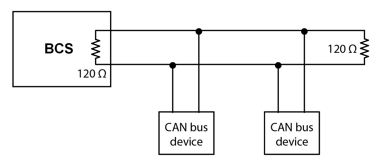
CAN assembly example diagram