Troubleshooting
In case of any issue with software, read BCS PDI Builder user manual -> Troubleshooting.
Warning
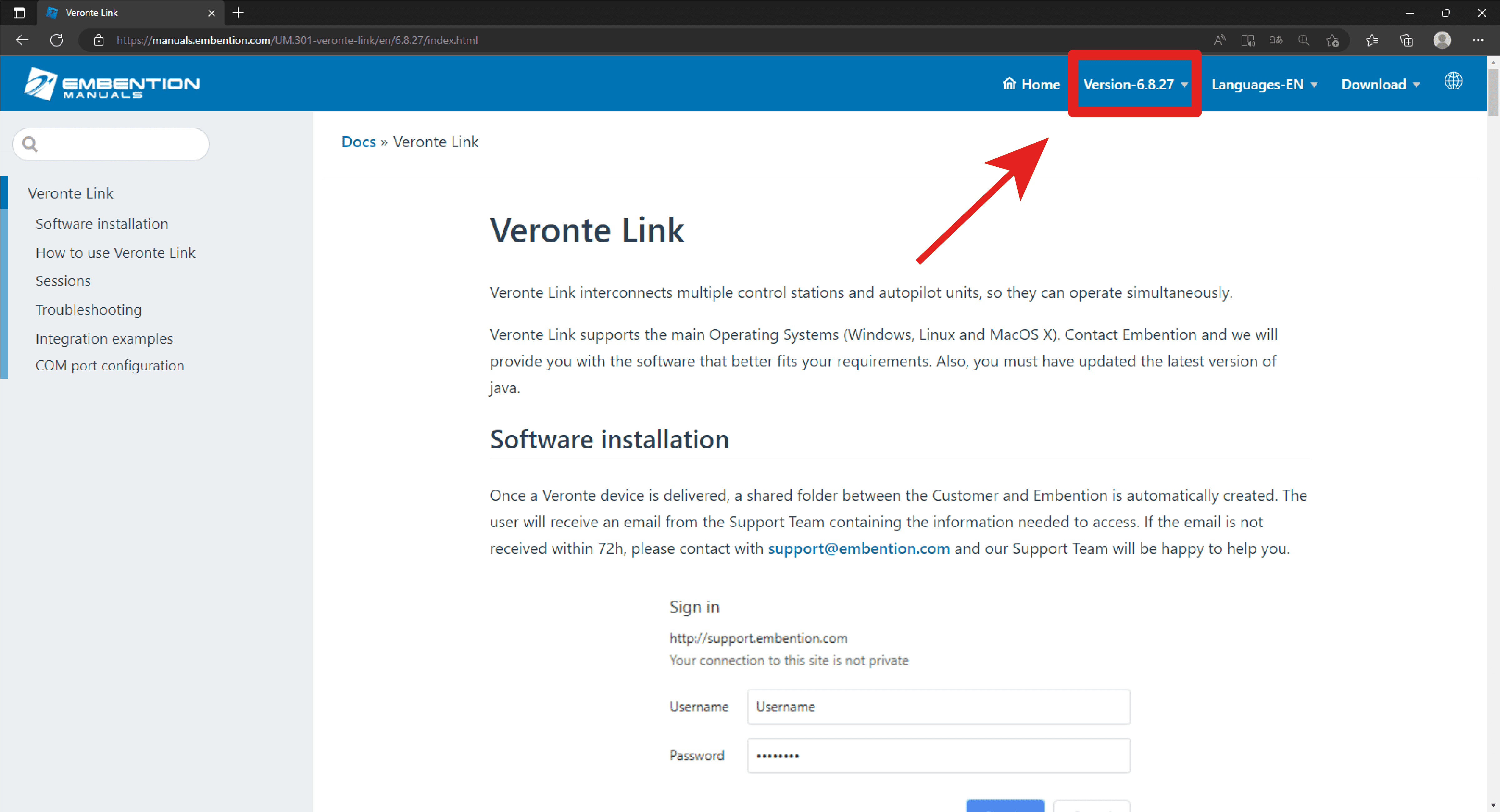
Select your version before reading any user manual for software. The following image shows where to select a version from any Embention user manual.
Maintenance mode
Maintenance mode is the main troubleshooting tool that BCS puts at the user disposal. While in maintenance mode, all communication channels are enabled by default, so it is possible to connect with BCS through any of its interfaces, no matter its current configuration.
The main use of maintanance mode is to solve issues related to the current configuration, mainly with communication or memory writting issues.
While in maintenance mode, it is possible to perform actions such as force the load of a new configuration file.
If at some point the communication with BCS is lost, it is possible to use maintenance mode to go back to a previous state of the configuration.
Tip
It is heavily recommended to always use maintenance mode to load a new configuration that is very different from the current one.
How to enter in maintenance mode
There are two ways to enter in maintenance mode: using software or forcing it.
Using software to enter in maintenance mode
To enter in maintenance mode using software, read BCS PDI Builder user manual -> Maintenance Mode.
Forcing maintenance mode
There are two ways to force the maintenance mode: using power supply or using the I2C pins.
Using the power supply to force maintenance mode
When communication with the unit is lost, it is possible to active maintenance mode by power input.
In order to active maintenance mode, power cycle the BCS repetively with a period of 1 second. After 30 cycles, the autopilot will enter in maintenance mode.
BCS might enter in maintenance mode if a problem with the power supply is detected upon boot up (voltage or current is out of range).
How to power cycle
Using the I2C pins to enter in maintenance mode
To enter in maintenance mode with I2C, connect both I2C pins each other, then power up the BCS. Both pins are I2C_CLK (number 31) and I2C_DATA (number 32) according to the pinout.