1. Veronte Ops configuration
This section describes all the menus, options and actions that allow the user to modify the configuration and appearance of this application. These are:
Status bar
In the status bar, the user can view mission and operation relevant information, as well as modify general Veronte Ops settings.
Status bar
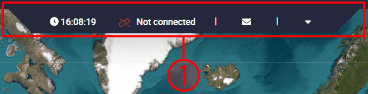
This bar is divided into 3 ‘parts’:
Status bar items: Clock, Weather and Platform selected information items are grouped here.
The user can choose to show/hide each of these elements from the Status bar settings.
By default, the clock and the selected platform are shown, as can be seen in the image above.
Notifications: Veronte Ops notifications for users. This is always displayed in the status bar.
More options: By clicking on this drop-down menu, users will find options for configuring this application and its appearance.
Notifications
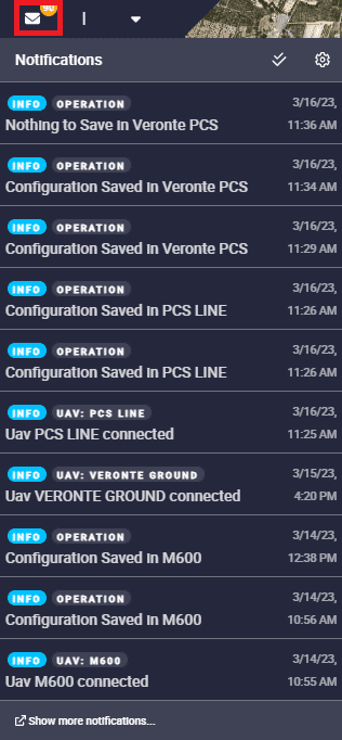
Veronte Ops will notify the user of any changes made with notifications (visual and audible, the latter is optional), as shown in the figure below:
Notifications menu
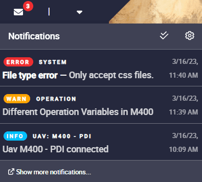
In addition, notifications are classified into 3 groups (Information, Warning and Error) with a colour code (blue, orange and red respectively):
Notifications menu - Classification
These notifications can be marked as read by clicking on the ![]() icon at the top of this menu. So, they will no longer be displayed in this menu.
icon at the top of this menu. So, they will no longer be displayed in this menu.
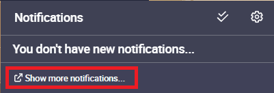
Notifications readed
However, if the user wishes to consult them, simply clik on ‘Show more notification…’ and a new window will appear with the entire history of notifications. Here the user can search for notifications or delete them:
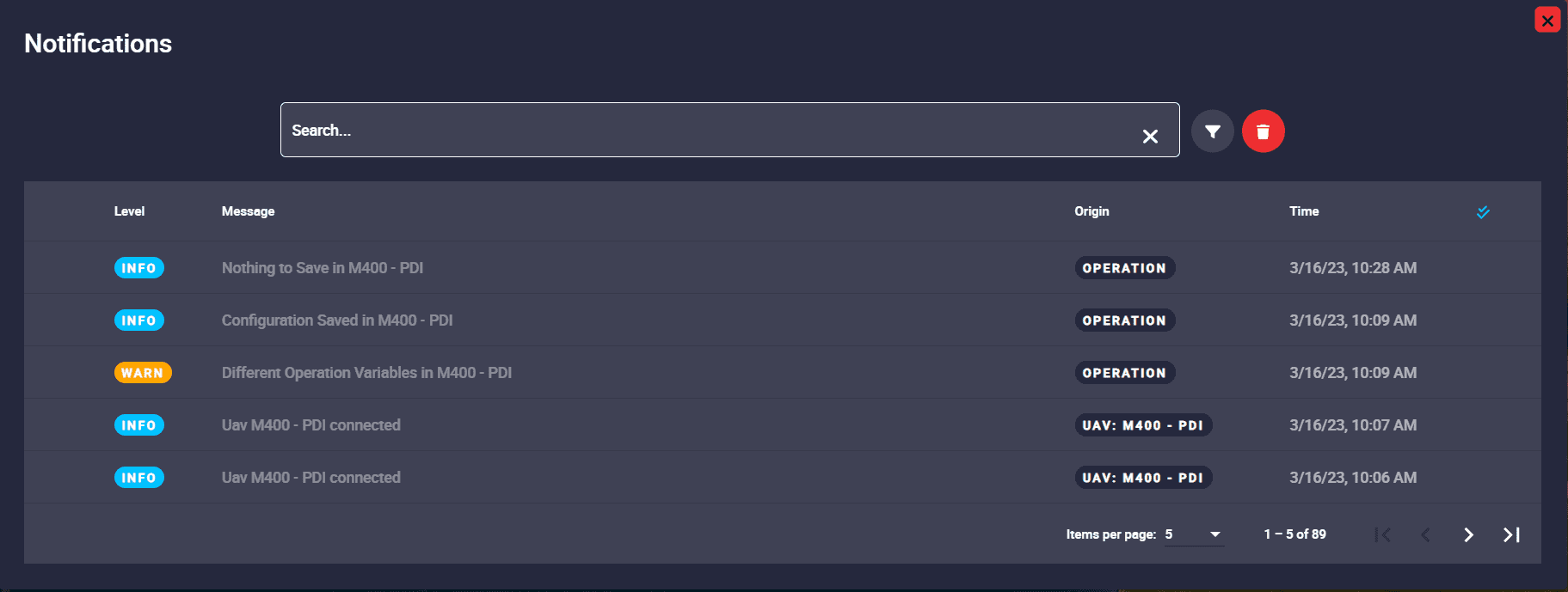
History of notifications
Besides, in the notification configuration users can choose, to some degree, which groups of notifications are shown or not. This is to a certain degree because, as the classification described above has been defined according to importance, error notifications will always be shown (as they are the most important ones) but warning and information notifications can be chosen to be seen/heard or not.
To access it, simply click on the ![]() icon at the top of this menu:
icon at the top of this menu:
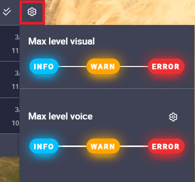
Notifications menu - Configuration
Besides, the user can also choose the language of the sound notifications by clicking on the settings icon:
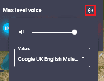
Sound notifications language
Below is an example of how to customize the notification settings:
Modified notifications
More options
Moreover, by clicking on the drop-down menu on the right, users will find more options, such as:
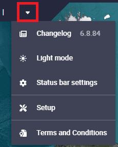
Drop-down menu
Changelog
Users can consult the changelog, which shows all updates made to the application.
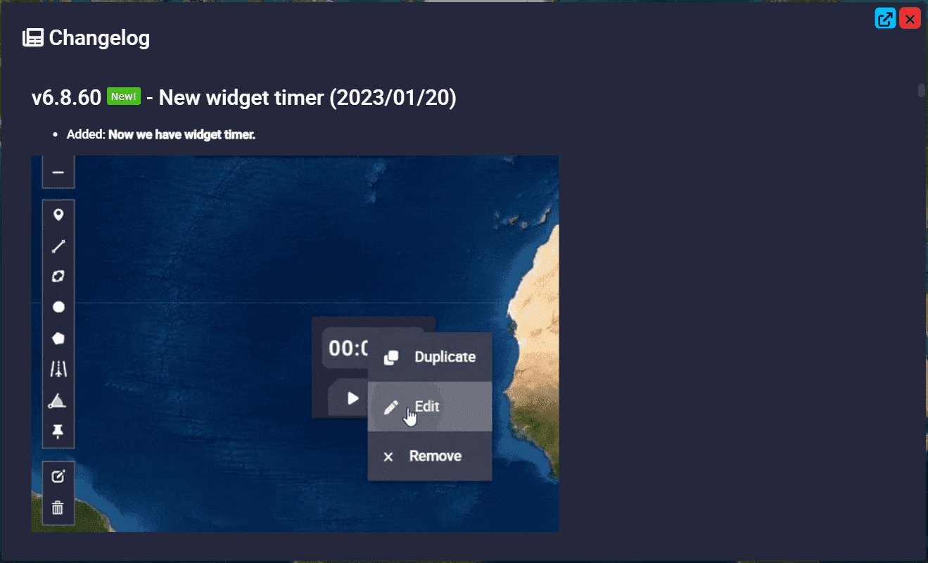
Changelog
Light/Dark mode
Change the interface display mode: Light/Dark mode.
Light/Dark mode
Status bar settings
This menu allows the user to enable/disable the information items in the status bar.
Note
To save any changes, click the “Save” button in the bottom right corner of the menu.
Weather
This option will only be available if the user has geolocation enabled, i.e. the browser has permissions to use the user’s geolocation.
In order to do this:
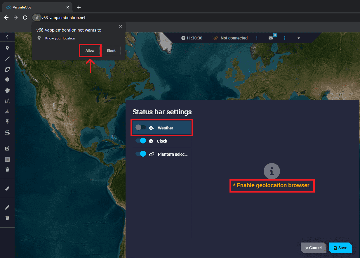
Weather section - Enable geolocation
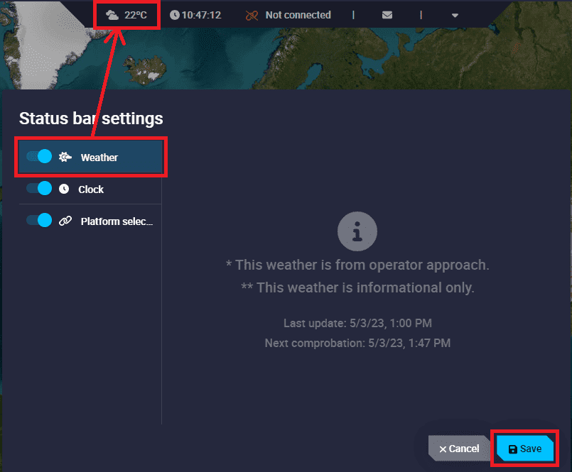
Weather section
Clock
It is possible to customize the timezone where users are working.
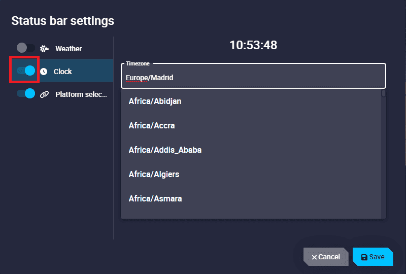
Clock section
Platform selected
This element informs the user whether a Veronte Autopilot 1x is not connected, connected, disconnected or in maintenance mode, and the name of this device.
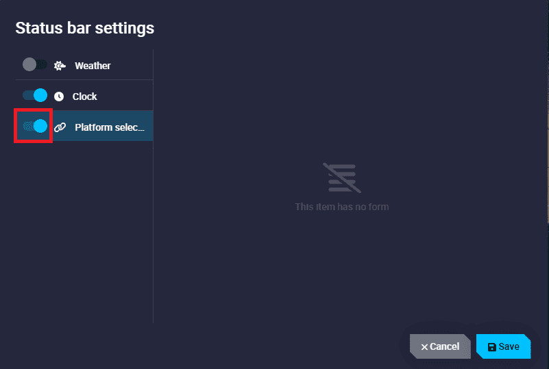
Platform selected section
The figures below show all 1x autopilot states:


Setup
This menu allows to edit the general settings of Veronte Ops:
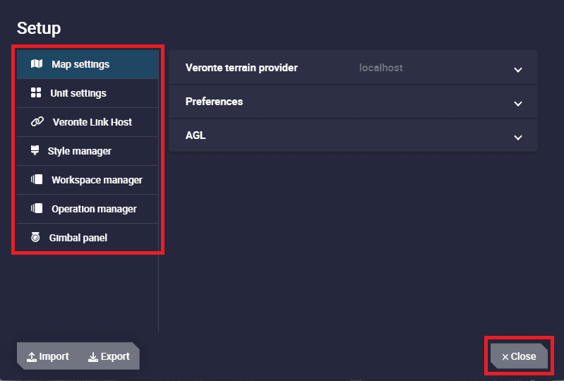
Status bar - Setup
Note
Clicking the ‘Close’ button, in the bottom right corner of the menu, will close this window and save any changes made.
Map settings
In this menu, it is possible to edit the terrain data settings, such as:
Veronte Ops SRTM data provider: By default, this is the additional application Veronte terrain provider, but users can enter another SRTM data provider that is on the PC.
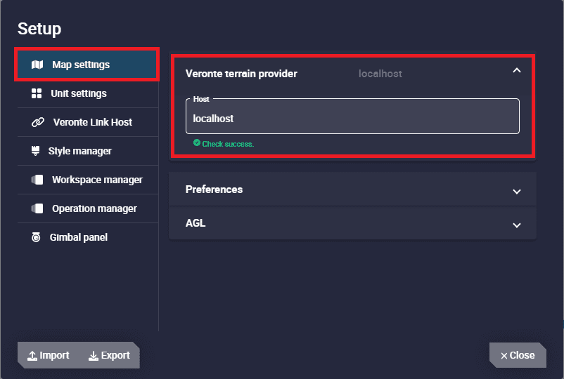
Map settings section - Veronte terrain provider
Preferences
Users can customize the coordinates and height units of the map.
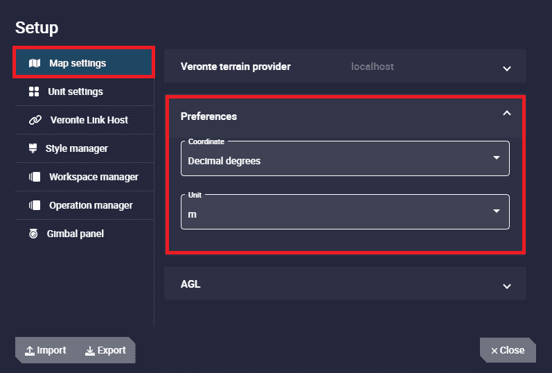
Map settings section - Preferences
Coordinate: Select the units of the coordinates. The available options are Decimal degress, Degrees, UTM and MGRS.
Unit: It is possible to select the units of the height from the drop-down menu.
AGL
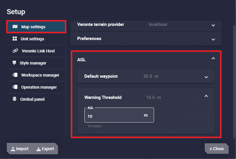
Map settings section - AGL
Default waypoints: Enter the default altitude, in AGL, of the waypoints created.
Warning Threshold: It is possible to add a warning threshold to avoid collision with terrain. This will appear as a line when users open the ‘elevations’ option in the created route.
For example, if the warning threshold is set to 10 metres, a red warning line will be drawn in the ‘elevations’ menu 10 metres above each terrain point.
Also, if the mission path intersects this line, Veronte Ops will interpret this as the route colliding with the terrain:
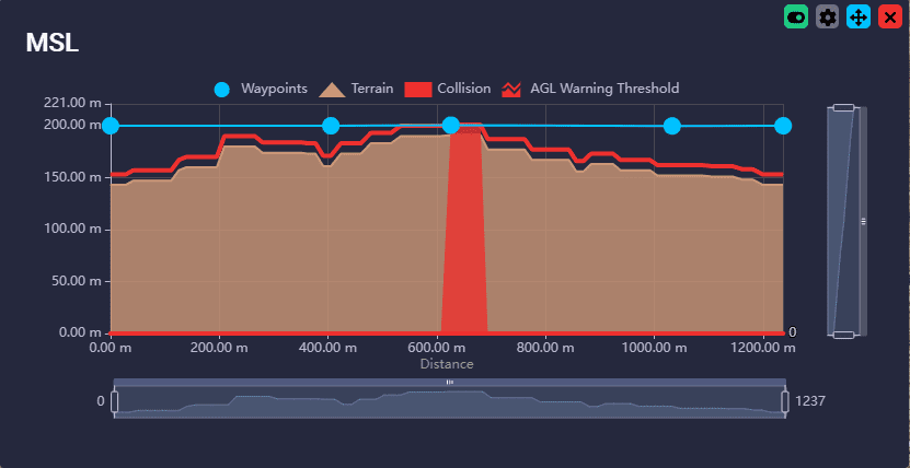
Map settings section - Warning
Unit settings
This panel shows all the system units available for the system variables.
They are sorted by variable type in alphabetical order: acceleration, temperature, velocity, etc.
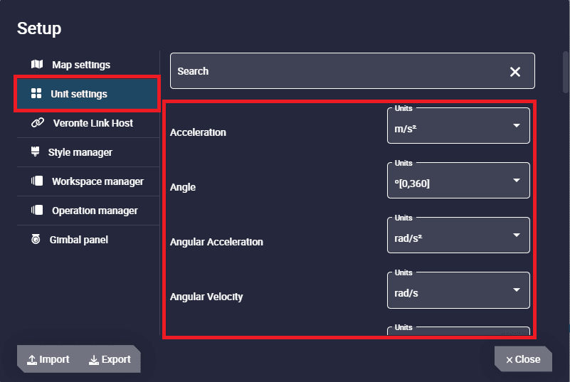
Unit settings section
The following table shows all the units available in Veronte Ops:
Variable Type
Units
Acceleration
[m/s²] [ft/s²] [in/s²] [g]
Angle
rad[-π;π] °[-180;180] °[0;360] [° ‘ “] [rad] rad[0;2π] °
Angular Acceleration
[rpm/s] [rad/s²] [rad/m²] [rad/h²] [°/s²] [°/m²] [°/h²]
Angular Velocity
[rad/s] [rad/m] [rad/h] [rps] [rpm] [rph] [°/s]
Area
[m²] [cm²] [mm²] [km²] [mile²] [ft²] [yd²]
Baudrate
[Bd] [kBd] [MBd]
Centimeters/Pixels
[cm/pixel]
Current
[A] [mA]
Data
[bit] [byte] [KB] [GB] [bytes/s]
Decibel
[dB]
Density
[kg/m³]
Flow Rate
[m³/s] [gal/s] [gal/h] [l/s] [l/h]
Force
[N] [kN] [lbf] [pdl]
Frequency
[Hz] [mHz] [kHz]
Jerk
[m/s³]
Length
[m] [km] [mi] [NM] [yd] [ft] [in] [cm] [mm]
Magfield Variance
[T²]
Magnetic Flux Density
[T] [mG] [gauss] [nT]
Mass
[kg] [g] [tonnes] [lbs] [oz]
Numeral System
[bin] [octal] [dec] [hex]
Percentage
[x1] [%]
Power
[W] [kW] [Kgm/s] [erg/s] [CV]
Pressure
[Pa] [kPa] [bar] [mbar] [psi] [mmHg] [at] [atm]
Pressure Square Error Rate
[Pa²/s]
Pressure Variance
[Pa²]
Resistence
[Ω]
Temperature
[K] [°C] [°F]
Time
[s] [min] [h] [μs] [ms] [Time]
Transfer
[pkts/s]
Velocity
[m/s] [kt] [km/h] [mph] [ft/s] [mm/s] [ft/m]
Velocity Variance
[(m/s)²] [(cm/s)²] [(mm/s)²]
Voltage
[V] [mV]
Volume
[m³] [dm³] [mm³] [L] [mL]
Veronte Link Host
As Veronte Link is the Embention application that stores, reads and manages all the configurables of the products, the user can choose which Veronte Link to use to access the data, to access certain products.
By default, the IP address ‘localhost’ is set, which is the Veronte Link on the same PC as Veronte Ops. However, it is also possible to connect Veronte Ops to a Veronte Link running on a different computer, simply by entering the IP address of that computer, so Veronte Ops will be able to access the devices connected to it.
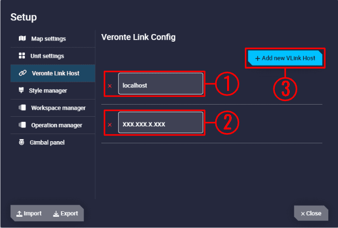
Veronte Link Host section
In the image above, users can identify:
The local IP: ‘localhost’
The IP address of another computer
Add a new VLink Host: It is possible to have access to several Veronte Link and therefore multiple users can manage the same Veronte Link, the same products.
If the user has any problems when trying to connect Veronte Ops to Veronte Link, see Troubleshooting section -> Connecting to Veronte Link of this manual.
Style manager
This section allows the user to import and export custom widget styles.
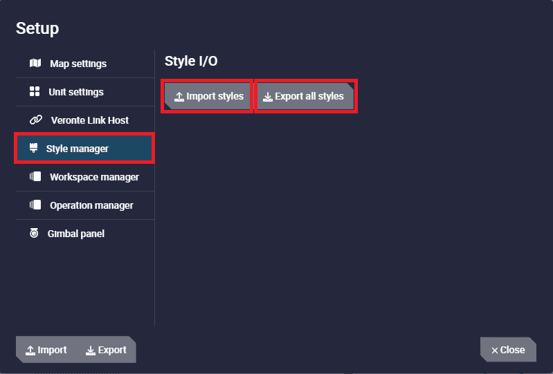
Style manager section
Import styles: By clicking here, users can import custom styles as a zip folder or by directly selecting all desired custom styles
.cssfiles.When the styles are imported, a notification will appear:

Style manager section - Import notification
Export all styles: By clicking here, all custom styles will be exported as a zip folder:
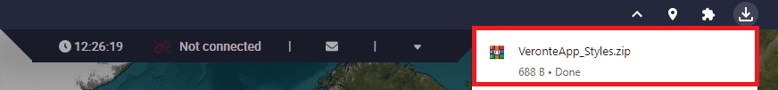
Style manager section - Export
Note
Default widget styles will not be exported.
The zip folder will contain all the
.cssfiles with custom styles for the different widgets, ametadata.jsonfile and aREADMEfile: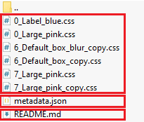
Style manager section - Exported files
metadata.json file: This file contains the IDs of the styles that are assigned to the workspaces.
Danger
It is advisable not to modify this file.
README file: Pay special attention to this file to find out how to create or modify a style.
Workspace manager
From this panel users can delete one, several or all workspaces created.
To do this, simply select the workspaces to be deleted and then click on the ‘Delete’ button.
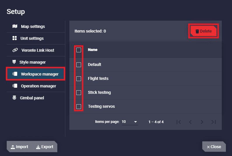
Workspace manager section
Operation manager
From this panel users can delete one, several or all operations created.
To do this, simply select the operations to be deleted and then click on the ‘Delete’ button.
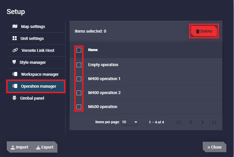
Operation manager section
Gimbal panel
Users can add a predefined gimbal from this panel:
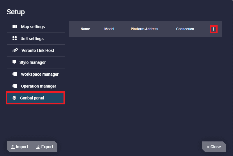
Gimbal panel section
Clicking the
 icon displays the following configuration panel to add a new gimbal:
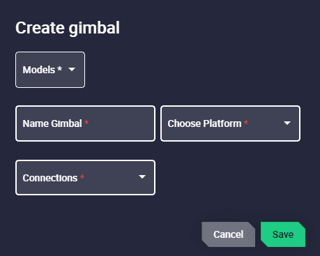
Gimbal panel section - Create gimbal
Models: Select a gimbal model from the list.
Name Gimbal: Enter the desired name for the gimbal to be added.
Choose Platform: Users must select the platform for which the gimbal is configured.
The available options will always be the IDs of the connected autopilots 1x and ‘Selected platform’, i.e. the platform that is selected.
Connections: The type of connection through which Veronte Ops sends commands to the gimbal must be selected:
Veronte Tunnel: When choosing this connection type, Veronte Autopilot 1x tunnel is used to send commands to the gimbal.
Users must also specify the Veronte tunnel port used: 1, 2 or 3.
Warning
Be careful! This port must match the Tunnel port configured in the 1x PDI Builder software.
WebSocket: In order to send commands via the Web Converter application, it is required to enter the websocket_url configured in that tool in the URL field and copy the websocket_port configured as the camera’s udp connection in the port field.
Advanced: Depending on the gimbal model chosen, some additional options can be configured which are characteristic of each gimbal.
Note
This option will only appear after the selection of the gimbal model.
Then, the created gimbal will appear on the panel:
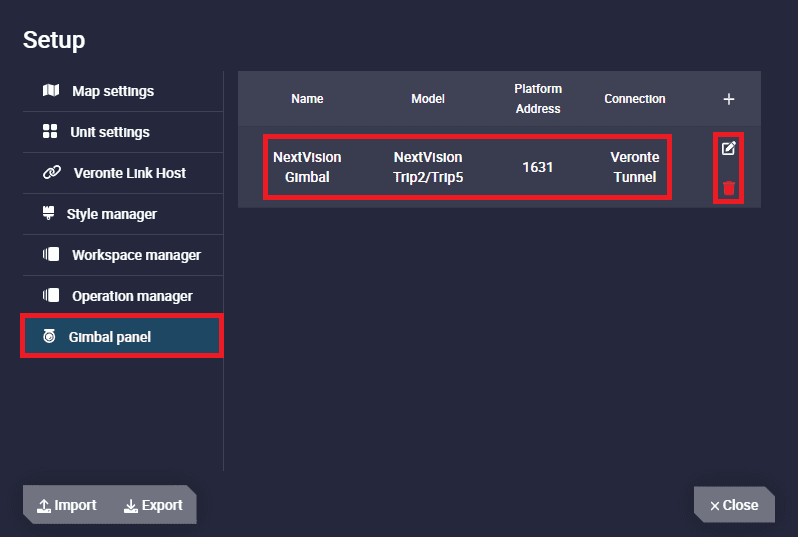
Gimbal panel section - Gimbal added
 Edit gimbal: Allows the user to access again to the configuration menu described above.
 Remove Gimbal: Removes this gimbal.
Import/Export buttons
Furthermore, all these settings can be exported and imported from one Veronte Ops to another, for example to move them from one PC to another.
When the user tries to import a new Veronte Ops configuration, the following confirmation message will appear:
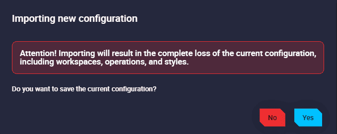
Import Veronte Ops configuration
Terms and Conditions
Users can consult the ‘End User License Agreement (EULA)’ by simply clicking on this button.
Feedback menu
Feedback button
Press the button above to access the Feedback menu:
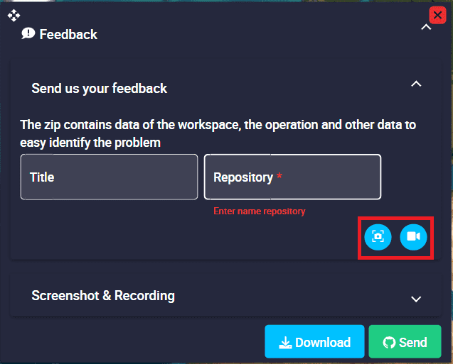
Feedback menu
Users can report a problem they have encountered by creating an issue in their own ‘Joint Collaboration Framework’
Note
The user’s ‘Joint Collaboration Framework’ is simply a own Github repository for each customer.
In case of having any question about this Joint Collaboration Framework, please read its user manual.
It is also possible to take a snapshot or a recording of that problem.
Clicking on the ‘Download’ button downloads a zipped folder with the data of the workspace, the operation and other data to easily identify the problem. It is advisable to attach this folder when creating the issue.
Finally, by clicking on the ‘Send’ button, a Github window will open in the browser with an issue. This issue is created in the repository indicated before with the title that has been defined.
Find below an example of the creation of a feedback:
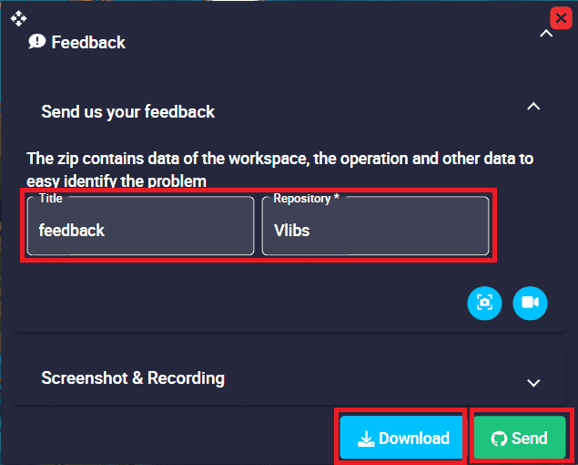
Feedback example - Feedback menu
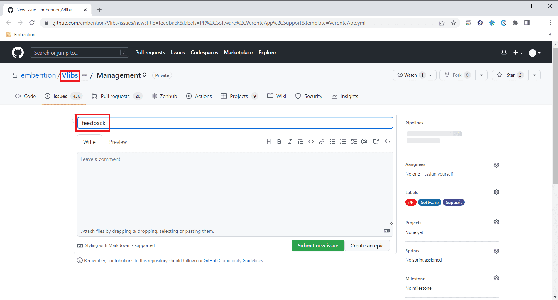
Feedback example - Issue created in Github
Background configuration
It is possible to edit the background behind the map. To access this editing menu it is necessary to first minimize the map (or hide it) and then right click on the background:
Access background edition
In this menu, users will find:
Background edition
Widget options: The user can change the refresh frequency of the workspace, of the widgets. By default this frequency is 100 miliseconds.
Background options: Choose the type of background style between a color or an image:
Color: Users can select the desired color for the background.
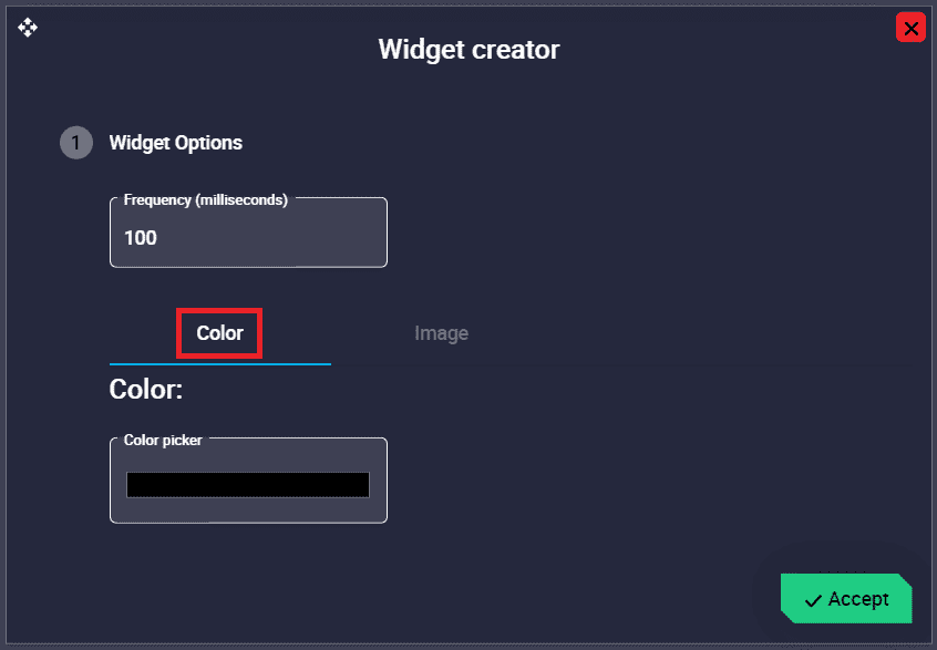
Background - Color
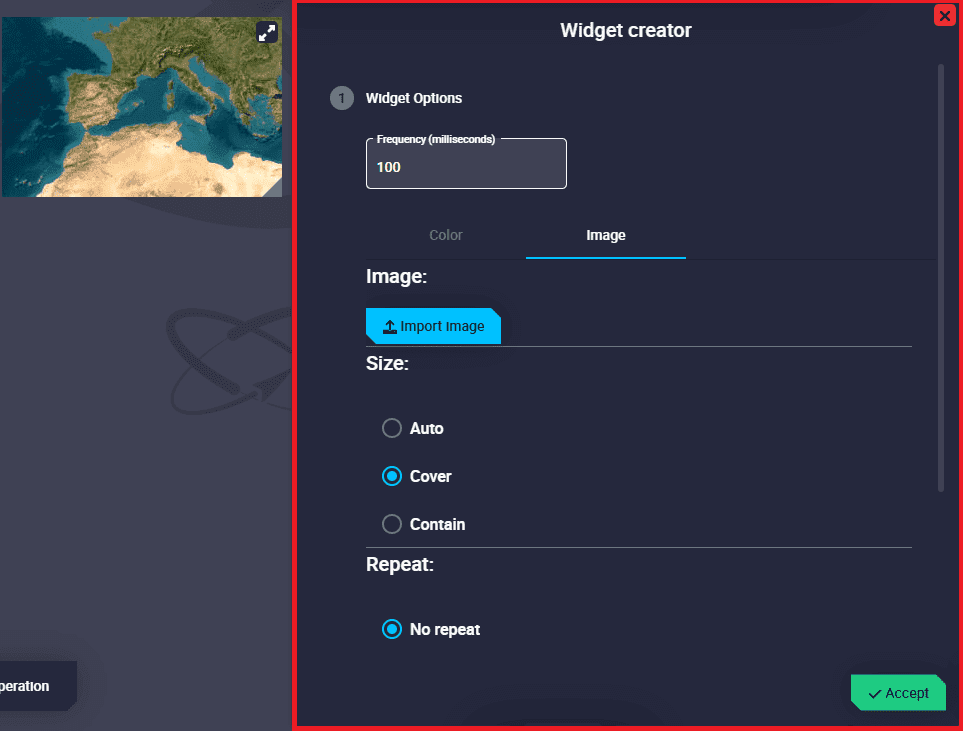
Image: When choosing ‘Image’, users must configure some parameters:
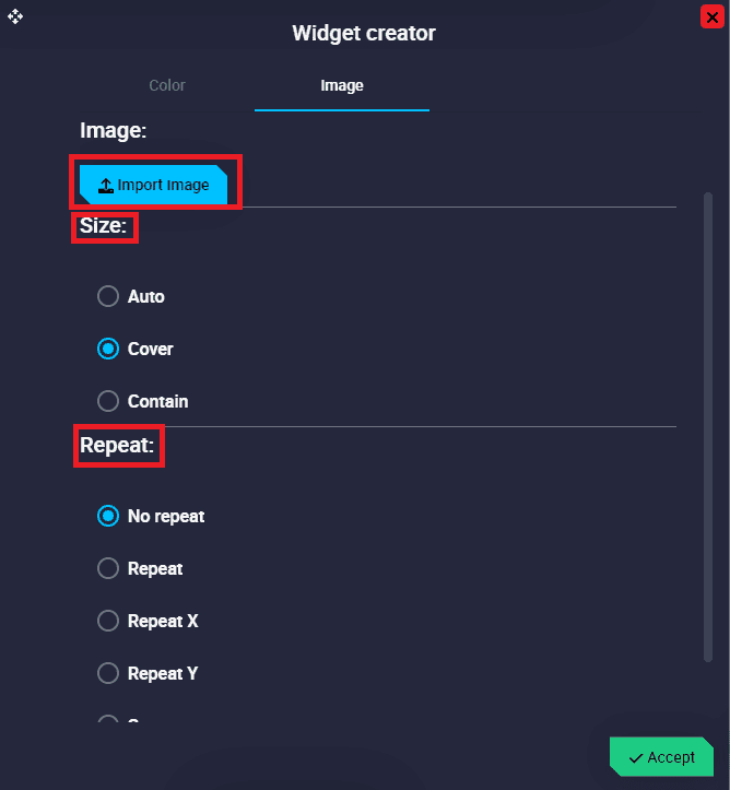
Background - Image
Image: A Veronte Ops image is set by default, but it is possible to import another image from the local PC.
Size: The size of the background can be modified, the available options are: Auto, Cover and Contain.
Repeat: The repetition of the image can also be customized, choose from: No repeat, Repeat, Repeat X, Repeat Y, Space and Round.
Platform icon
This icon allows the user to locate and follow the position of the platform at any time during the operation.
By right-clicking on it, users will access its options:
Platform icon options
Follow: Keeps the platform always centered on the map during operation.
Settings: Users will access to the settings menu:
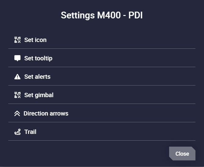
Platform icon settings
Set icon: Users can customize the icon that will be used to represent the position of this unit on the map. Simply choose one of the default icons or upload one from the laptop.
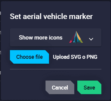
Platform icon settings - Set icon
Set tooltip: Allows the user to display a variable next to the platform icon.
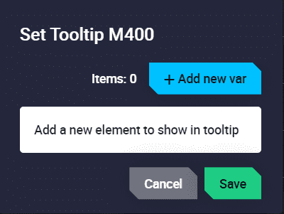
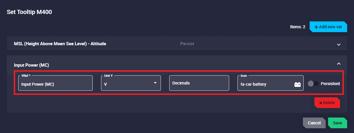
Platform icon settings - Set tooltip
The following parameters must be configure by clicking on ‘Add new var’:
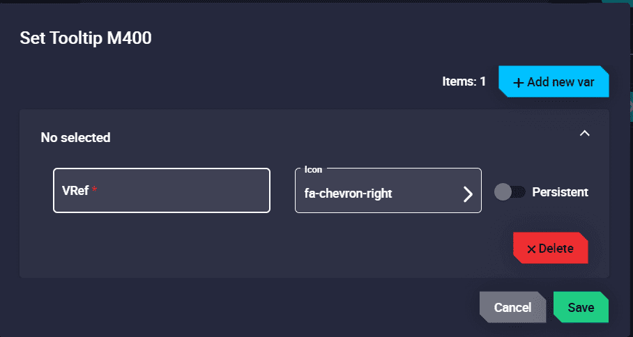
Platform icon settings - Set tooltip configuration
VRef: Select the desired variable to be displayed.
Unit and Decimals: The units and decimals can also be modified. These parameters will appear depending on the variable chosen.
Icon: Choose the icon to be shown next to the variable.
Persistent: When enabled, this tooltip will remain displayed during the operation. Otherwise, it will only appear when clicking on the icon.
An example is shown here:
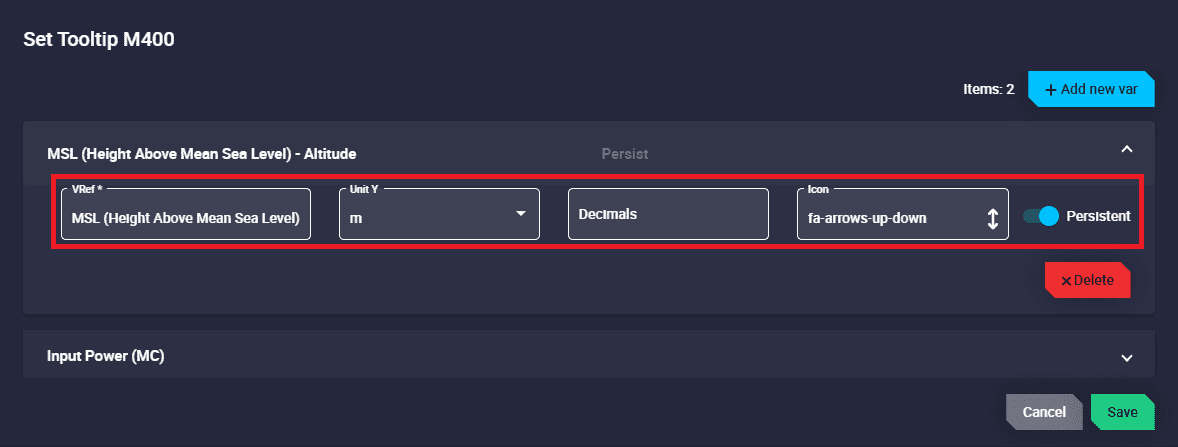
Platform icon settings - Set tooltip example
Platform icon settings - Set tooltip example
Platform icon settings - Set tooltip example
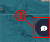
Set alerts: These alerts are bit variables that appear next to the platform icon when in ‘error mode’.
By default, the same bits that are sent in the autopilot ‘Status Message’ are configured as alerts. The user can add as many alerts as desired.
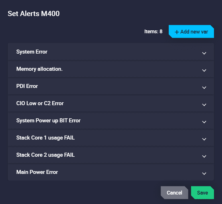
Platform icon settings - Set alerts
They are displayed with the icon, which has been configured with them, flashing red when in ‘error mode’. When the platform icon is clicked on, the name of the variable that has triggered this alert will be displayed. An example is shown below:

Platform icon settings - Set alerts
Set gimbal: Allows the display of information on the map provided by the selected gimbal.
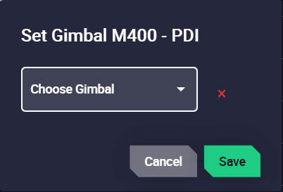
Platform icon settings - Set gimbal
Choose Gimbal: Select the desired gimbal to add from those previously configured in the Gimbal panel.
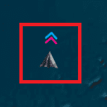
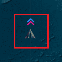
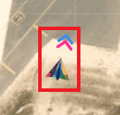
Direction arrows: Users can change the color of the yaw and heading arrows.
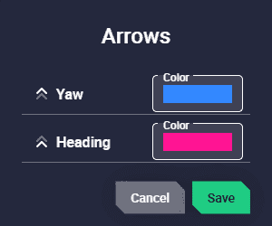
Platform icon settings - Direction arrows
Trail: The trail path of the platform can be customized.

Platform icon settings - Trail
Color: Set the color trail.
Dash line length: Sets the length of the dash line. This change is visualized when a number other than of 0 is set.
Dash line space: Sets the space between dash lines. This change is visualized when a number other than of 0 and greater than dash line length is set.
Pick Up Time: Sets the time for the first point of the trial to be removed. This change is visualized when the time is other than 0 s.
Max distance: Sets the maximum length of the path to be drawn.
Fly to loiter: Create a volatile loiter and change the current route.
Note
The platform will remain the altitude it had before this command.
Platform icon - Fly to loiter
Fly to hover: Create a volatile waypoint and change the current route.
Note
The platform will remain the altitude it had before this command.
Platform icon - Fly to hover
Follow leader: With this action the platform will follow a moving object (it can be another platform). For more information on this, see Follow Leader automation of the 1x PDI Builder manual.
The platform icon changes its appearance depending on the situation:
Platform disconnected:
When Autopilot 1x is not connected, the platform icon is ‘translucent grey’
By default, it is placed in the world coordinates (0,0).
Platform icon - Translucent grey
Platform connected:
During operation/configuration creation:
The platform icon is ‘translucent colored’, indicating that GPS data is not being received, i.e. Position not fixed status.
By default, it is placed in the world coordinates (0,0).
Platform icon - Translucent colored
During operation/simulation:
The platform icon is ‘colored’, indicating that GPS data is being received/simulated.
It is placed in the actual position/simulation position.
Platform icon - Colored