Operation
All the tools in this ‘section’ allow the user to design the mission, such as waypoints, segments, marks, runways, etc.
 Waypoint
Use the Waypoint tool and click on the map to create new waypoints. Then, when users have created all the desired waypoint, right-click on the map to close/finish the ‘creation event’.
To move waypoints, it is first necessary to activate mission editing by clicking on the ![]() icon. Then, simply drag it to the desired position.
icon. Then, simply drag it to the desired position.
In relation to waypoints, the following actions can be performed with the mouse:
Clicking once on the waypoint will display a summary of the waypoint information, coordinates and elevation:

Waypoint information
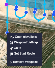
Right-clicking on the waypoint, users will access to its options:
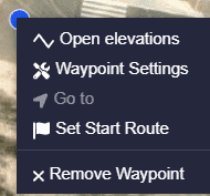
Waypoint options
Remove waypoint: Deletes the waypoint.
Set Start Route: Users must define where they want the cruise route to start by defining the waypoint as such with this option. The waypoint will turn of green color.
Warning
If users do not define any waypoint as the ‘Start Route’, the operation will not be uploaded to the autopilot configuration and the following warning notification will be displayed:

Set start route - Warning notification
Go to: By clicking here, the platform will fly to this waypoint. If the waypoint belongs to a mission, the platform will continue that mission after reaching it.
Note
This option is only available when a Veronte Autopilot 1x is connected and the operation, which the user is working on, is stored in the autopilot.
Waypoint Settings: The user can change the configuration of the waypoint (coordinates and elevation) in the menu displayed here:
Waypoint configuration
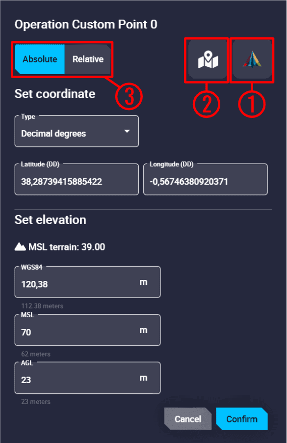
There are 3 ways of defining the position of a waypoint manually:
Matching it to the platform position. By selecting the
 icon, the waypoint coordinates and elevation will be automatically updated with those of the actual platform’s actual position.
Selecting a position in the map. Simply click on this icon
 , then click on the desired point on the map and the waypoint coordinates and elevation will be updated automatically.
Entering the exact coordinates and elevation here:
Absolute:
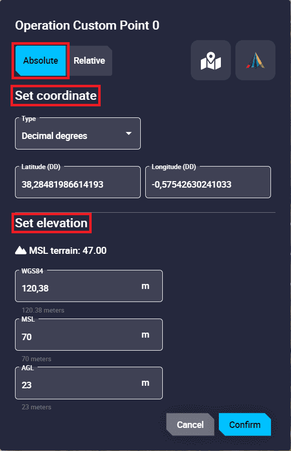
Absolute waypoint position
Set coordinates: The coordinates can be set in:
Decimal Degrees \(\rightarrow\) Latitude (DD) and Longitude (DD)
Degrees º ‘ ” \(\rightarrow\) Latitude (DMS) and Longitude (DMS)
UTM \(\rightarrow\) x (Easting), y (Northing), Zone and Hemisphere
MGRS (Military Grid Reference System)
Set elevation: Whichever way the user defines the altitude (WGS84, MSL and AGL) Veronte Ops will calculate the other 2 ways. That is, if the user defines a waypoint at X m in AGL, Veronte Ops will automatically calculate what that value is in WGS84 and MSL.
Relative: In this case, the position of the waypoint is relative to another point.
That point could be the UAV position, a Desired position, a Track position or an Operation Custom Point. They are indicated through North, East and Down.
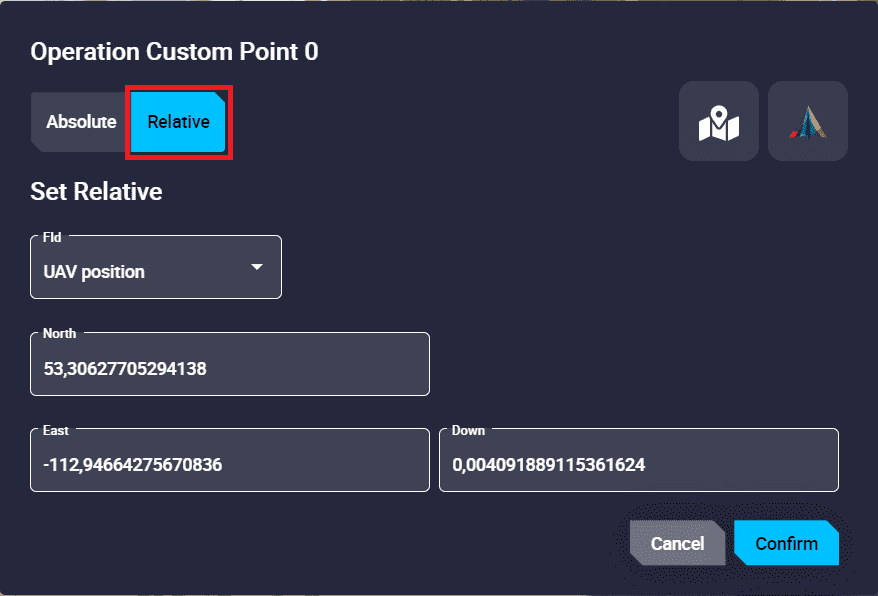
Relative waypoint position
Open elevations: To be able to consult the elevation of the route, it is required to have installed the Veronte Terrain Provider application (for more information about this, see Additional apps section of this manual).
Here users can see an estimate of the height of the terrain and the height of the route to be taken as well as the collisions that could occur.
In addition, users can set up a Warning Threshold, which will be represented as a red warning line over the terrain. Fore more information, see Map settings section of this manual.
By clicking on it, the following menu will appear:
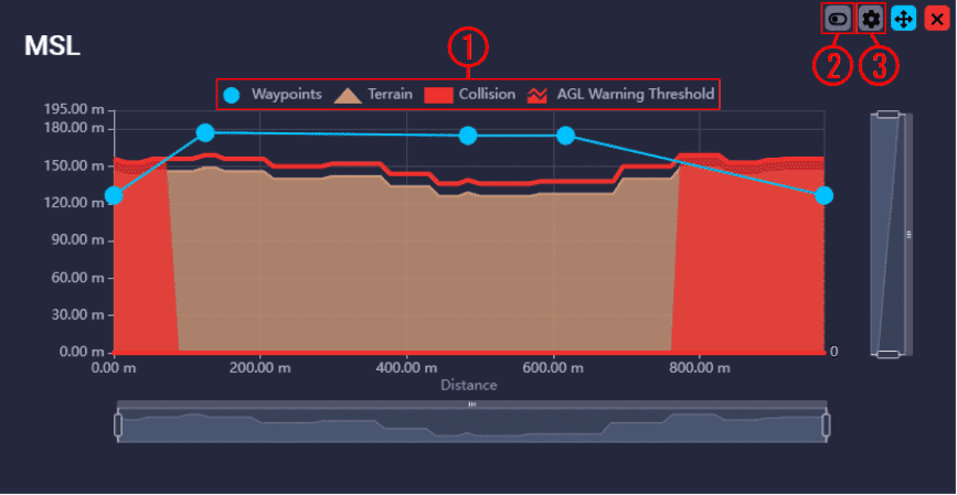
Elevation (MSL) menu
This legend showing waypoints, terrain and collision is an ‘interactive’ legend, i.e. users can choose which of these elements are displayed or not by simply clicking on them:
Elevation (MSL) menu - Legend
Drag button: When enabled (
 ), users can modify the altitude of the waypoints by simply clicking and dragging them. If it is disabled (
 ), it is not possible to move them:
Elevation (MSL) menu - Dragging waypoints
Settings button: Displays a new window with some parameters that can be customized:
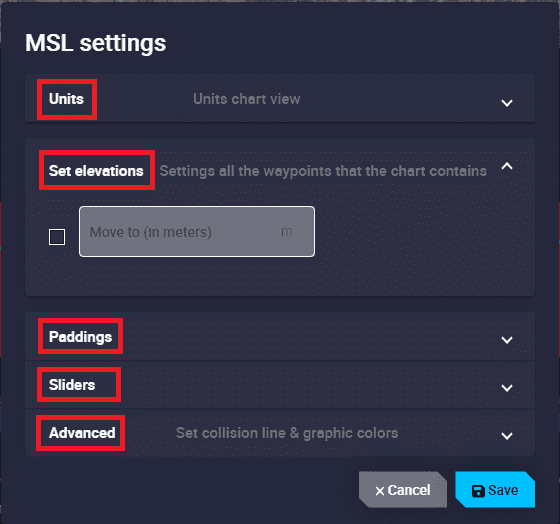
Open elevation menu - Settings
Units: Units of the elevation and distance of the chart view can be set.
Set elevations: The altitude of all waypoints on the route can be modified.
Paddings: The size of the grid can be adjusted as desired.
Sliders: X and Y axis sliders can be hidden by disabling them.
Advanced: The collision line and chart colors can be modified:
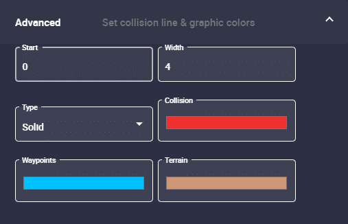
Elevation (MSL) menu - Advanced settings
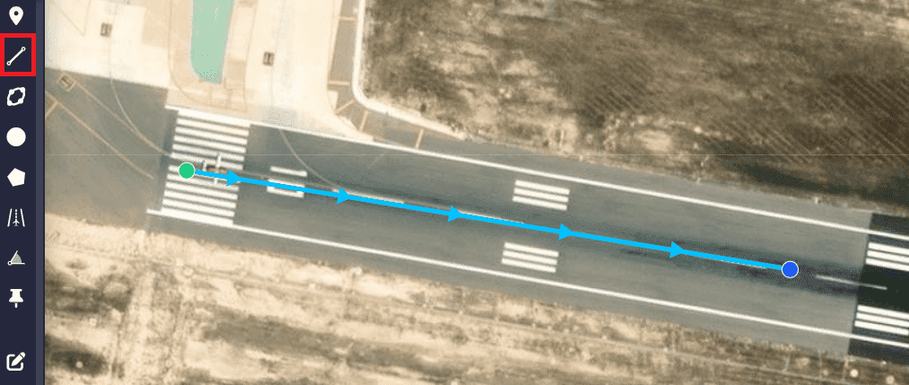
 Segment
To create a new segment, click on the segment icon and then select on the map the point where the segment will start. To end the track, users have 2 options:
Double click directly with the left mouse button will create the last waypoint of the segment.
After creating the last waypoint, right-click on the map to close/finish the ‘creation event’.
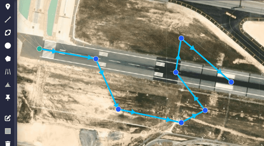
Segment
In addition, users can concatenate two or more segments by clicking on various points on the map with the left button, as shown in the figure below:
Route
Besides, to create a closed route, users must match the last waypoint of the segment with the first one:
Closed route
It is also possibe to curve a segment. To do so, users must create the segment, edit the mission by clicking on the ![]() icon, and then move the translucent orange waypoint (
icon, and then move the translucent orange waypoint (![]() ) in the centre of the segment.
The distance moved will correspond to the radius of the curve:
) in the centre of the segment.
The distance moved will correspond to the radius of the curve:
Curve segment
There is an extra option in the options for a waypoint that corresponds to the start of a curved segment:
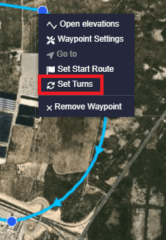
Curve segment options
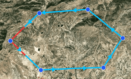
Set Turns: This option allows the user to set a desired number of turns. After these turns the platform will continue with the defined mission. An example is shown below:

Curve segment - Turns
Warning
When a segment is created, be careful with the height of the waypoints.
Users can check for collisions between route waypoints and terrain directly on the map or using the ‘Open elevations’ functionality described above.
To check directly on the map, if some of the waypoints are below the terrain altitude indicated by the meshes, the affected segment will change its color to red. To solve this, change the altitude of the waypoints. An example is shown below:
Segment under the ground altitude
 Orbit
This tool allows the user to create a new orbit on the map.
First, select a point on the map which will be the center of the new orbit. Then, when users have created all the desired orbits, right-click on the map to close/finish the ‘creation event’.
Orbit
In addition, the initial circular orbit can be converted into an ellipse by modifying the length of the axes and can also be rotated.
To do this, edit the mission by clicking on the ![]() icon, then move the 4 translucent orange waypoints (
icon, then move the 4 translucent orange waypoints (![]() ) as desired to turn them into an ellipse and to rotate it, click and rotate the small blue circle (
) as desired to turn them into an ellipse and to rotate it, click and rotate the small blue circle (![]() ):
):
Ellipse orbit
Besides, there is an extra option in orbits regarding waypoints and segments:
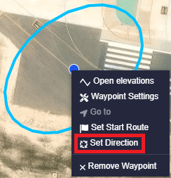
Orbit options
Set Direction: It is possible to select the direction of the loiter: Auto, Clockwise and Anticlockwise.
Warning
When creating an orbit, be careful with its altitude and the ground level (all the points of the orbit will be at the same altitude).
Users can check for collisions between orbit and terrain directly on the map or using the ‘Open elevations’ functionality described above.
To check this directly on the map, if any part of the orbit is below the terrain altitude indicated by the meshes, the affected segment will change its color to red. To solve this, change the altitude of the waypoint.
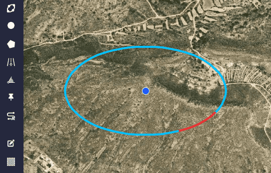
Orbit partially below ground level
 Circle
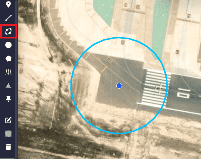
This tool is used to determinate an area in which an action is wanted to be performed. When the aircraft enters or leaves the circle an event may be triggered and it can be used to start an automation.
Note
The linking of a circular area to an automation is done in the Operation panel, for more information about this, see Operation panel section of this manual.
To add a circle, click on its icon, click on the desired point on the map and drag it to set the radius. Then, when users have created all the desired circles, right-click on the map to close/finish the ‘creation event’.
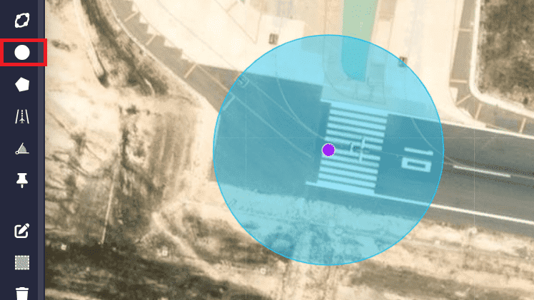
Circle
Like all other elements, it can be edited to move it or change its radius by clicking on the ![]() icon:
icon:
Circle radius
Right-clicking on the circle, users will access to its options:
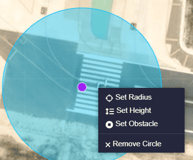
Circle options
Set Radius: To accurately set the radius of the circle, users can enter the value manually.
Set Height: Users can set the upper and lower heights of the circular area. By default, circular areas have infinite lower and upper boundaries.

Circle options - Set Height
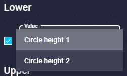
As can be seen in the figure above, the lower and upper limits can be set as absolute or relative:
Relative
 icon: The altitude is relative to a Operation Variable, previously defined in 1x PDI Builder. But, it is required to set the value of the variable in the Operation Variables of the Operation panel.
In addition, it is necessary to establish whether it is relative to AGL, MSL, WGS84 or to a Fld (feature) that has to be selected.
Circle options - Height relative
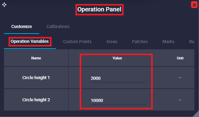
Circle options - Operation panel
Absolute
 icon: The value must be entered manually and it is also necessary to establish whether it is relative to AGL, MSL, WGS84 or to a Fld (feature) that has to be selected.
Set Obstacle: A circle can become an obstacle, an area that is desired to avoid.

Circle options - Set Obstacle
This tool permits to set an exclusion area on the map that can not be crossed by the RPAS. Main functions of the tool:
Avoid collisions with obstacles as for example buildings, trees or antenna towers.
Avoid flying restricted access areas.
What can happen with high speed aircrafts (Airplanes)? It is possible that due to its speed, the RPAS will enter the obstacle area, but will immediately apply the corrections to exit the obstacle area and return to the path. The solutions to this problem is to configure a bigger obstacle area in order to avoid the physical obstacle
What can happen with mow speed aircrafts (Multirotor)? It can happen that a multirotor enter an obstacle area (staying very close to its center), at that moment the Ground Speed Vector and the Field Repulsion Vector have the same direction but opposite sign. This phenomenon causes a conflict and until the directions are different enough to allow the multirotor to move, it will remain in an indecision situation. To solve this problem the user can configure the obstacle area by leaving the centre of the obstacle away from the path line.
There are some options available for each obstacle by right-cliking on it:
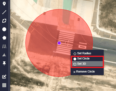
Cicle options - Obstacle options
Set 3D: This option allows the aircraft to avoid an obstacle by passing over it, taking into account the height of the obstacle.
Set 2D: This option only takes into account 2 dimensions for the obstacle. Therefore, the platform will not be able to avoid the obstacle passing over it.
Set circle: Turns the obstacle back into a circular area.
Remove Circle: Deletes the circle.
 Polygon
The way it works is very similar to Circle, described above.
This tool is used to determinate an area in which an action is wanted to be performed. When the aircraft enters or leaves the polygon an event may be triggered and it can be used to start an automation.
Note
The linking of a polygonal area to an automation is done in the Operation panel, for more information about this, see Operation panel section of this manual.
To add a polygon, click on its icon, click on the desired points on the map and match the last waypoint of the polygon with the first one. Then, when users have created all the desired polygons, right-click on the map to close/finish the ‘creation event’.
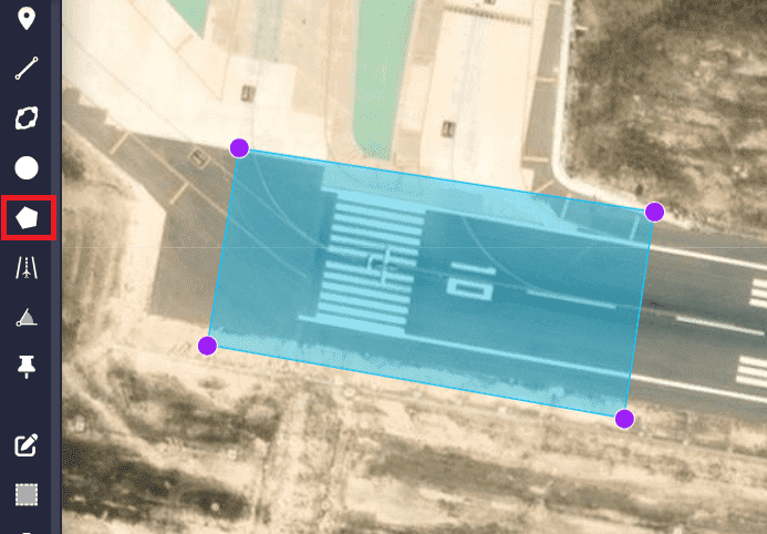
Polygon
Like the other elements, it can be edited to change its shape by moving its vertices. Click on the ![]() icon:
icon:
Polygon shape
Right-clicking on the polygon, users will access to its options:
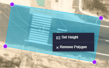
Polygon options
Set height: Users can set the upper and lower heights of the polygonal area. By default, polygonal areas have infinite lower and upper boundaries. It works in the same way as in the circular areas, described above.
Remove polygon: Deletes the polygon.
 Runway
This option allows the user to configure a Runway which is used during flight phases.
To add a runway, click on its icon, click on a point on the map to define the start and click on a second point to define the end of the runway.
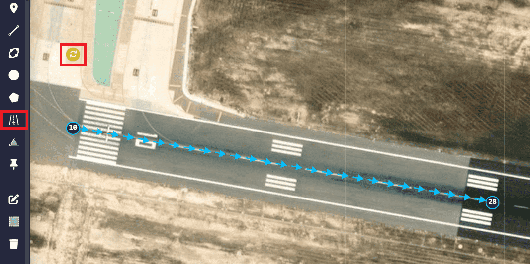
Runway
Note
The loiter position is automatically defined and it is identified by this icon: ![]() , as can be seen in the image above.
, as can be seen in the image above.
By accessing the mission edition (![]() icon) it is possible to modify the position of the start and end points of the runway, as well as the position of the loiter point:
icon) it is possible to modify the position of the start and end points of the runway, as well as the position of the loiter point:
Runway position
Right-clicking on the start or end point of the runway, users will access to its options:
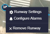
Runway options
Runway Settings: The following parameters can be configured:

Runway options - Settings
Runway direction: The direction of the runway is defined here with an arrow.
By default it is \(\rightarrow\), but user can define it as desired clicking on it. The available options are \(\rightarrow, \leftarrow\) and AUTO.
Note
When the AUTO option is selected, the runway direction will be defined by the wind direction.
Runway coordinates: The user can manually introduce the coordinates of the start and end point of the runway. Its configuration is the same as for a waypoint (a detailed explanation of this has been described in the Waypoint section).
Margin/Margin Reverse: Percentage of the runway distance at which the airplane will try to touch the ground.
Loiter Position: To accurately define the loiter point of reference (Runway Loiter), its coordinates and the altitude that the aircraft will reach during climb, can be defined in this option.
Its configuration is the same as for a waypoint (a detailed explanation of this has been described in the Waypoint section).
Configure Alarms: When an alarm is selected, the aircraft shall perform the actions associated to that alarm on the selected runway.
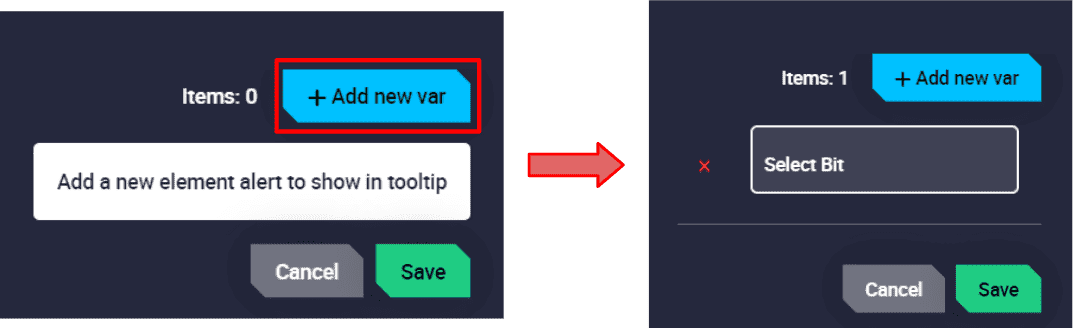
Runway options - Configure Alarms
Alarms are configured with bit variables, users can select any bit they want.
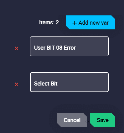
Runway options - Alarms
Remove Runway: Deletes the runway.
 Spot
Spot
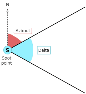
This option allows the user to configure a Spot which is used during flight phases. A spot refers to a kind of runway where a initial point and its azimuth is defined. Besides, it is necessary to define a delta angle.
Spot
Note
The loiter position is automatically defined and it is identified by this icon: ![]() , as can be seen in the image above.
, as can be seen in the image above.
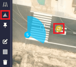
By accessing the mission edition (![]() icon) it is possible to modify the position, azimuth and delta of the ‘spot’ and also the position of the loiter point:
icon) it is possible to modify the position, azimuth and delta of the ‘spot’ and also the position of the loiter point:
Spot position
Right-clicking on the ‘spot’ point, users will access to its options:
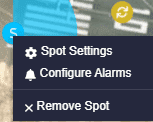
Spot options
Spot Settings: The aircraft will land or take-off using the best orientation computed within the area bounded by the parameters entered here:
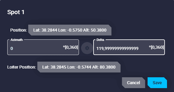
Spot options - Settings
Position: The user can manually introduce the coordinates of the ‘spot’ point. Its configuration is the same as for a waypoint (a detailed explanation of this has been described in the Waypoint section).
Azimuth and Delta: Users must configure the desired azimuth and delta for the spot. The units available for these angular values are \(º [0,360],\) º ‘ ” , \(rad, rad [0,2 \pi], \, º \, , rad[-\pi, \pi]\) and \(º[-180,180]\).
Spot parameters
Loiter Position: To accurately define the loiter point of reference (Spot Loiter), its coordinates and the altitude can be defined in this option.
Its configuration is the same as for a waypoint (a detailed explanation of this has been described in the Waypoint section).
Configure Alarms: When an alarm is selected, the aircraft shall perform the actions associated to that alarm on the selected spot. It is configured in the same way as runways, described above.
Remove Spot: Deletes the spot.
 Marks
This tool allows to set an event mark on a patch. Marks are useful to initiating automations. When the aircraft flies over it, an event is triggered and can be used as a condition to start a set of actions: add a lap to a counter, payload launch, take a photo, start video recording, etc.
Note
The linking of a mark to an automation is done in the Operation panel, for more information about this, see Operation panel section of this manual.
To place a mark, it is first required to create a patch. The elements described above that are patches are waypoints, segments and orbits. To add it, select the tool and click on the desired patch. Then, when users have created all the desired marks, right-click on the map to close/finish the ‘creation event’.
Initially, new marks appear as a pin (![]() ). If the user links an event to one of them, the icon selected for this event will be displayed.
). If the user links an event to one of them, the icon selected for this event will be displayed.

Mark
Marks can be moved along the patch by clicking on the ![]() icon:
icon:
Note
A mark can only be displaced if it is in a segment.
Marks moved
Right-clicking on the mark, users will access to its options:
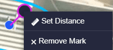
Mark options
Set Distance: This distance is the horizontal distance along the patch to the starting waypoint. If the mark is attached to a waypoint, distance will be zero.
Remove Mark: Deletes the mark.
 Generate route
To be able to create these elements, it is first necessary to have the application Veronte Terrain Provider running.
If this tool is not initialised, the following warning message will appear when trying to use the two ‘Generate Route’ tools:
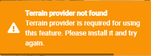
Generate route warning message
 Spiral
Spiral tool draws a spiral that can cover a target area.
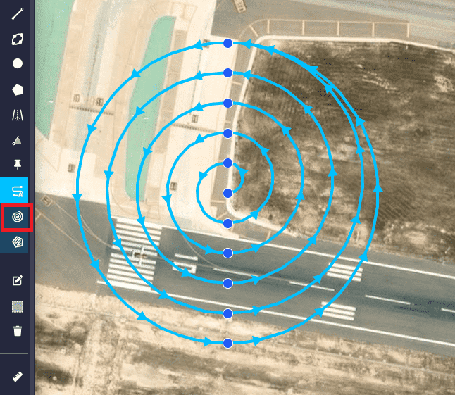
Generate route - Spiral
The spiral options are accessed in the same way as for the other elements described above, and are the same as the waypoint options. However, by clicking on the central waypoint of the spiral, an extra option appears that allows the user to access the ‘Spiral Settings’:
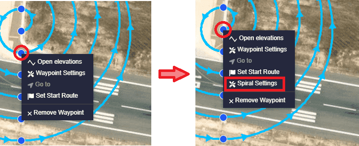
Generate route - Spiral options
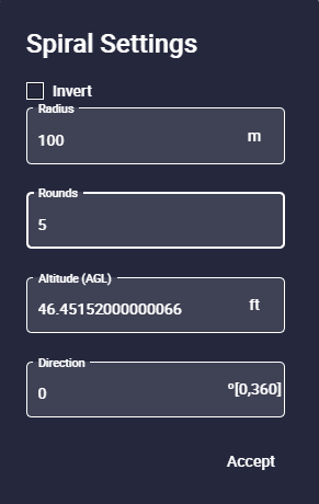
Generate route - Spiral Settings
Warning
If the user ‘refreshes’ Veronte Ops, it will no longer be possible to access this configuration menu.
In addition, the spiral will act as a curved segment and will have the same options like this one.
The following parameters can be configured:
Invert: When enabled, the direction of the route will be the opposite to the direction configured below.
Radius: Spiral maximum radius.
Rounds: The number of spiral rounds.
Altitude (AGL): Altitude of the waypoints expressed in AGL.
Direction: Direction of the spiral axes on the map.
 Photogrammetry Polygon
Polygon tool allows users to draw a polygon on the map to automatically generate a mapping mission.
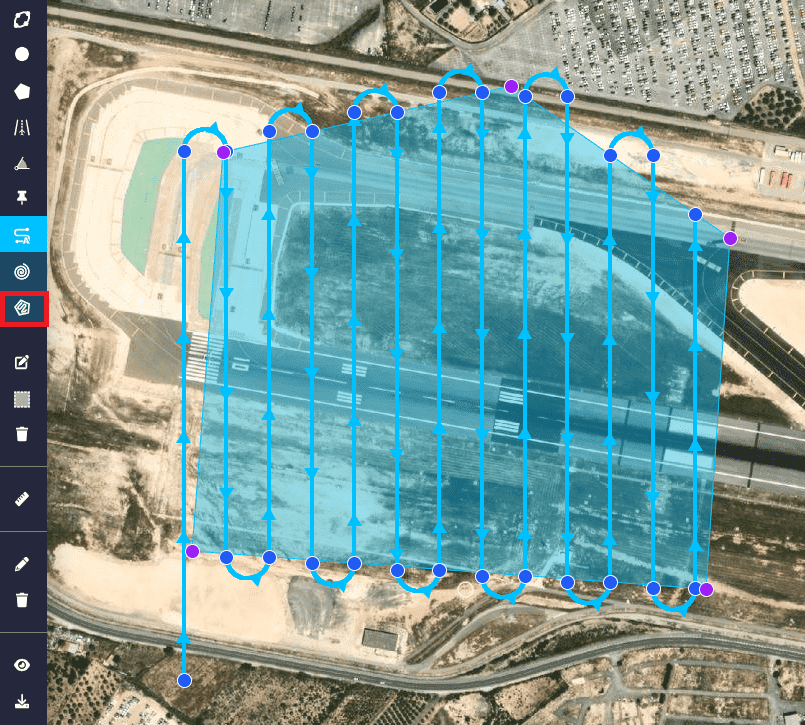
Generate route - Polygon
The polygon options are accessed in the same way and are the same as for a ‘normal’ polygon (see Polygon section, for more information). However, an extra option appears that allows the user to access the ‘Photogrammetry Settings’ (Route Settings):
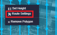
Generate route - Polygon options
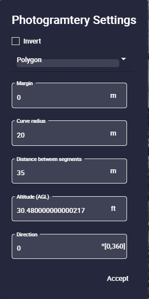
Generate route - Photogrammetry Settings
Warning
If the user ‘refreshes’ Veronte Ops, it will no longer be possible to access this configuration menu. Therefore, photogrammetry polygon will act as a “normal” polygon.
The following parameters can be configured:
Invert: When enabled, the direction of the route will be the opposite to the direction configured below.
Polygon: As with ‘normal’ polygons, users can link a predefined polygon to this photogrammetry polygon in the Operation panel. For more information about this, see Operation panel section of this manual.

Generate route - Photogrammetry Settings polygon
Margin: This option allows the user to add boundary margins for the route to each side of the polygon.
Curve radius: Radius of the route turns.
Distance between segments: Distance between segments can be modified.
Note
Depending on the curve radius value and the distance between segments, there are three cases for this part of the route (the radius must be set according to the minimum achievable by the platform):
Radius 0 \(\Rightarrow\) There are no curves between passes, but straight lines. This option is used with multicopters, which are able to perform this kind of paths.
Radius is smaller than half the distance between segments (\(R < \frac{d}{2}\)) \(\Rightarrow\) Veronte Ops generates a semicircle with the diameter equal to the distance between parallel segments.
Radius bigger than half the distance between segments (\(R > \frac{d}{2}\)) \(\Rightarrow\) The path between straight lines is formed by two curves and a straight line.
Altitude (AGL): Altitude of the waypoints expressed in AGL.
Direction: Direction of the route generated on the map.
Note
The options for the waypoints forming the route generated for this photogrammetry polygon are the same as for a ‘normal’ waypoint. For more information on waypoint configuration, see Waypoint section described above.
Generate route - Waypoint polygon options
 Mission panel
This mission panel allows the user to monitor and manipulate the waypoints, polygons and circles created.
Waypoints
The following fields can be found in this menu:

Mission panel - Waypoints
Name: Name of this waypoint defined in the 1x PDI Builder software.
Latitude/Longitude/MSL: Coordinates of the waypoint.
Position: Absolute or Relative.
Absolute means that the position of the element is fixed.
Relative indicates that its position is relative to the position of another element and may change during the operation.
Options:
 Search: Clicking here will center and zoom the waypoint on the map.
 Edit: Open the waypoint edit menu. For more information on waypoint settings, click here.
It is also possible to modify the altitude of one, several or all the selected waypoints by using the Altitude edit function on the top of the list.
Note
Selecting all will select the waypoints on all pages of the panel.
Users must enter the desired altitude value, select the altitude type (WGS84, MSL or AGL) and finally click ‘Set’.

Middion panel - Waypoints altitude
 Delete: Deletes this waypoint.
Polygons
The following fields can be found in this menu:
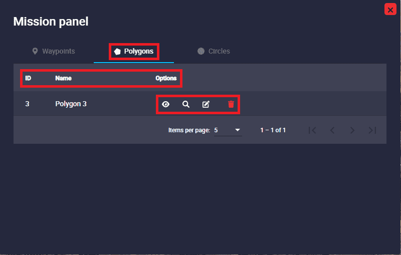
Mission panel - Polygons
ID: Feature Id of this polygon.
Name: Name of this polygon defined in the 1x PDI Builder software.
Options:
Show/hide: It is possible to show/hide the polygon on the map by clicking here.
Search: Clicking here will center and zoom the polygon on the map.
Edit: Open the polygon edit menu. For more information on polygon settings, click here.
Delete: Deletes this polygon.
Circles
The following fields can be found in this menu:

Mission panel - Circles
ID: Feature Id of this circle.
Name: Name of this circle defined in the 1x PDI Builder software.
Options:
Show/hide: It is possible to show/hide the circle on the map by clicking here.
Search: Clicking here will center and zoom the circle on the map.
Edit: Open the circle edit menu. For more information on circle settings, click here.
Delete: Deletes this circle.
 Edit mission
This tool allows the user to move waypoints, marks, areas, etc., as well as to change their shape.
A detailed explanation on how to use this tool can be found in each of the elements described above.
In addition, when modifying a mission with a Veronte autopilot 1x connected, the “original operation” loaded in the autopilot will be greyed out and the modified one will be coloured. This will be the case until the new changes are saved and uploaded to the autopilot, so the previous operation will be completely removed from the map. An example is shown below:
Edit mission
 Turn on multiselection
Multiselection allows to move and rotate mission’s path from one place on the map to another.
Select the tool and create a rectangle by clicking and dragging until the waypoints you want to move fall into it.
With the points selected, click and drag the rectangle to move it to the desired location. And to rotate it, click on the ‘white pin’ (
 ) and drag it to the desired rotation angle.
After that, click again in the tool’s icon to deselect.
Note
Runways and spots cannot be moved with this tool.

Multiselection tool
In addition, this tool also allows to delete all items selected by pressing the ‘delete’ key on the user’s keyboard.
Before deleting the selected items, the following confirmation message appears:
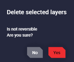
Multiselection tool - Remove message
Note
Runways and spots cannot be deleted in this way.
Multiselection tool - Remove
 Remove mission
By clicking on this icon, the user can remove all the elements created by simply clicking on each of them.
Remove mission
However, if the user wishes to remove all the missions created, simply click on the second icon that appears: ![]() .
A confirmation pop-up window will then appear to make sure that all missions wish to be deleted.
.
A confirmation pop-up window will then appear to make sure that all missions wish to be deleted.
Remove all missions