Mapping

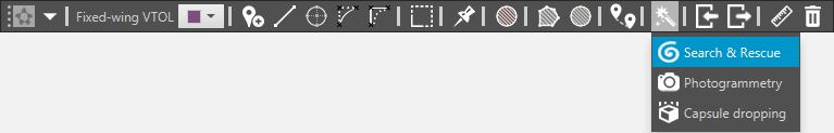
Mapping Tool Symbol
The Mapping tab includes a series of missions automatically generated from a set of parameters introduced by the user. So far, Veronte Pipe includes the following mission wizards:
Search & Rescue
Search & Rescue
Search & Rescue mission draws a spiral that can cover the target area. The spiral can be modified using the two black-gray points or opening the Search & Rescue Menu (double click on the route waypoints) and changing parameters:
Radius: spiral maximum radius.
Rounds: the number of spiral rounds.
Altitude: altitude of the waypoints. It can be expressed in AGL, MSL or WGS84.
Angle: inclination angle of the spiral axes on the map.
Length: length of the entire route.
Rotation: you can choose between clock-wise or counter clock-wise.
Search & Rescue Example
Photogrammetry
Photogrammetry
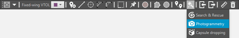
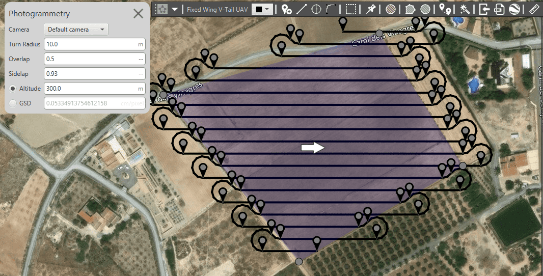
This tool allows users to draw a polygon on the map and configure camera parameters to automatically generate a mapping mission. Photogrammetry can be set from the mission tab by clicking on the Mapping icon and selecting photogrammetry from the list.
Photogrammetry Example
The process to configure a Photogrammetry mission:
Draw the polygon in which the drone will cover flying. If no camera is configured, a new window will appear when you close the polygon.
Camera specifications. Define the camera (or select it from the database included in Veronte Pipe by clicking on the hand lens icon). Veronte can stream the video signal selecting the Streaming option. If the camera is associated with a gimbal, it can also be defined here.
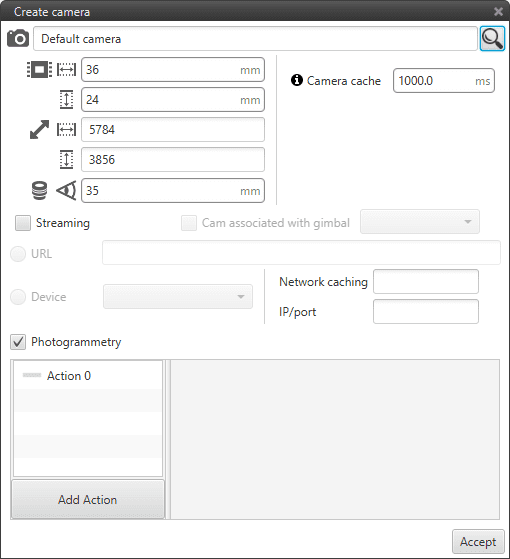
Camera Configuration
Five parameters appear below the camera name:
Width Sensor in millimeters.
Height Sensor in millimeters.
Width resolution in pixels.
Height resolution in pixels.
Focal length.
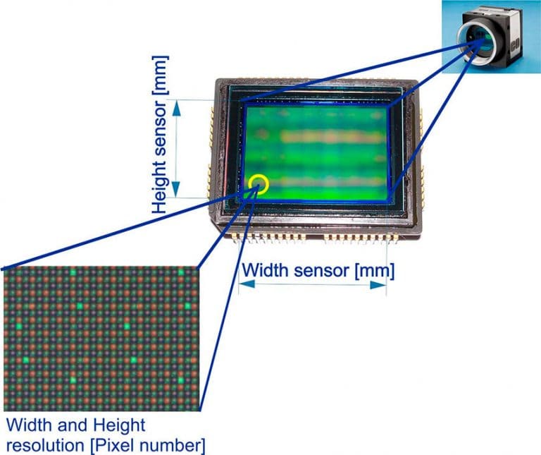
Sensor Parameters
Photogrammetry actions can be also added here.
Photogrammetry configuration.When your camera is created, it is time to configure your Photogrammetry process.

Photogrammetry Configuration
Camera. Select which camera you are using in the process.
Turn radius. radius of the route turns. Depending on this value and the distance between passes, there are three cases for this part of the route (the radius has to be established according to the minimum reacheable by the platform):
Radius 0, there are not curves between passes, but straight lines. This option is used with multicopters, which are able tor perform this kind of paths.
Radius is smaller than half the distance between passes (R<d/2). Pipe generates a semicircle with the diameter equal to the distance between parallel tracks.

Smaller Radius
Radius bigger than half the distance between phases (R>d/2). The path between straight lines is made up of two curves and a line.
Bigger Radius
Overlap. Desired overlap of the photos in the route direction. Its effect will be evident in the photos period changes.
Sidelap. Desired photos overlap in the different passes. Increasing this value will reduce the distance between the passes.
Altitude. Waypoints altitude in AGL.
GSD. Ground Sampling Distance in photogrammetry is the distance between two consecutive pixel centres measured on the ground.
Main Direction of the mission In the mission creation, at the centre of the created polygon, an steerable white arrow is present. When the arrow is turned, the mission will turn its main direction consequently. this is useful to avoid excessive wind exposition,for example.
The following image represents the mapping configuration variables in Veronte Pipe:
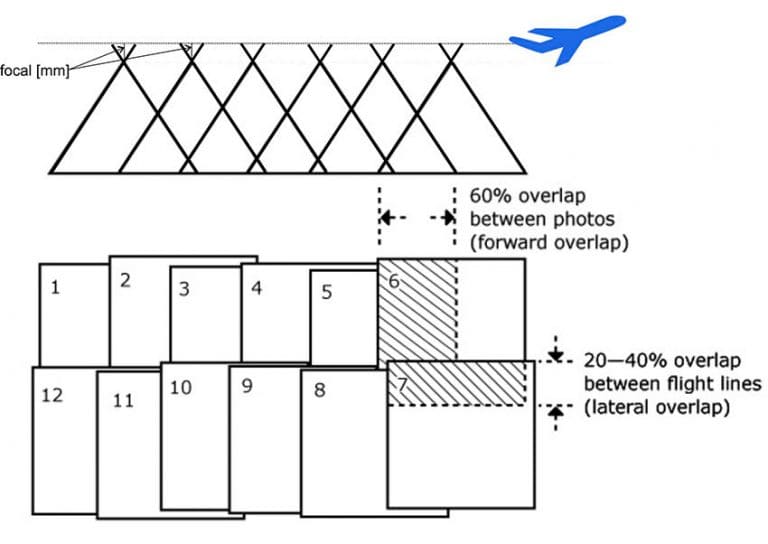
Overlap and Sidelap
When defining a Photogrammetry mission an automation will be created automatically. To complete the mission, in the lower part of the previous menu the option Photogrammetry has to be selected and the user must define the action that will be carried out, in this case taking a photo. The action (usually Output) has to be defined according to the hardware configuration on board. Once completed all the configuration, the automation will be created, by default its name is Mapping mission as showed in the two pictures below.
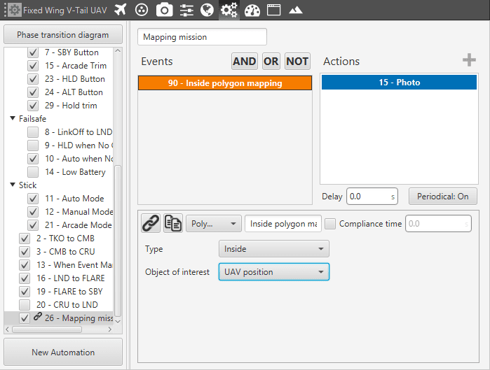
Mapping Automation Event
This automation tool offers you define automation as:
Inside area: the event will be carried out when the aircraft enter in the area.
Outside area: the event will be carried out when the aircraft leave the area.
Object of interest defines the object that have to enter or leave the area.
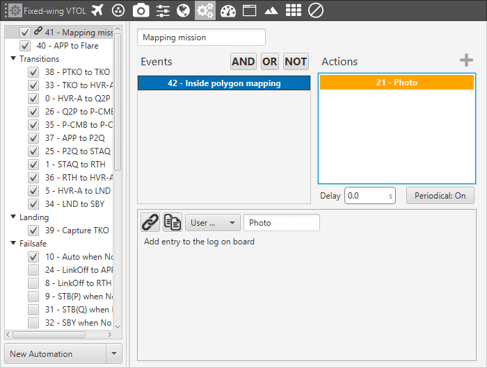
Mapping Automation Action
The action is carried out periodically in order to cover all the required area. Hence, the Period is computed in accordance with this and the camera specifications.
The configuration of the Photogrammetry mission is now complete. If the user wants to modify it, it can be done by changing the automation, the mission or the camera settings. The created camera can be found in the Devices panel as showed in the following figure.
It is also possible to configure a camera previously and select it after during the mission creation. How to add a new camera and configure it, is explained in Camera section.
Capsule Dropping
Capsule Dropping
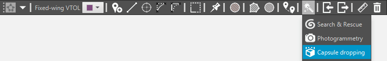
This tool can be used when the user wants to create automatically a mission which has the scope of periodically dropping payload when the platform is following the route.
To do this, open the Capsule Dropping tool from the Mission toolbar. The configuration of this kind of mission is exactly the same of the Photogrammetry but menu and automation are different.
The process to configure a Capsule Dropping mission:
Clicking on the map, draw the polygon which indicates the zone the drone will cover with its flight. When you close the polygon, a new window will display.
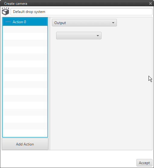
Capsule Dropping Configuration
When your camera is created, it is time to configure the Capsule Dropping process.
The routes can be modified by changing the parameters in the menu which shows up when a waypoint of the mapping mission is clicked. The following parameters can be set:
Drop: the Dropping system can be configured in the tool menu and switched from this list.
Turn Radius: radius of the route turns. In this case, the default configuration has the turn radius set to 0, but the effect of this parameter on the curve form is the same as in the case of photogrammetry mission.
AGL: waypoints Above Ground Level altitude.
Distance: distance between two parallel routes of the mission.
Period: dropping period in [s].
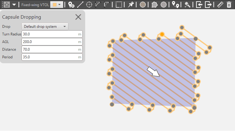
Capsule Dropping Configuration
As in the photogrammetry case, when the mission is defined, the previous menu will show up allowing the user to define the Capsule Dropping mission actions. The automation is then created as showed in the following image.
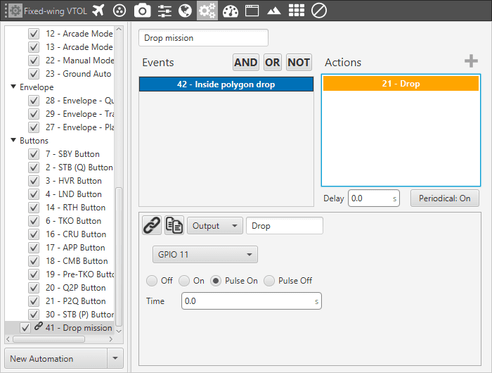
Capsule Dropping Automation Event
The configuration of the Capsule Dropping mission is now complete. If the user wants to modify it, it can be done by changing the automation, the mission or the dropping system settings. The created dropping device can be found in the Devices panel as showed in the following figure.
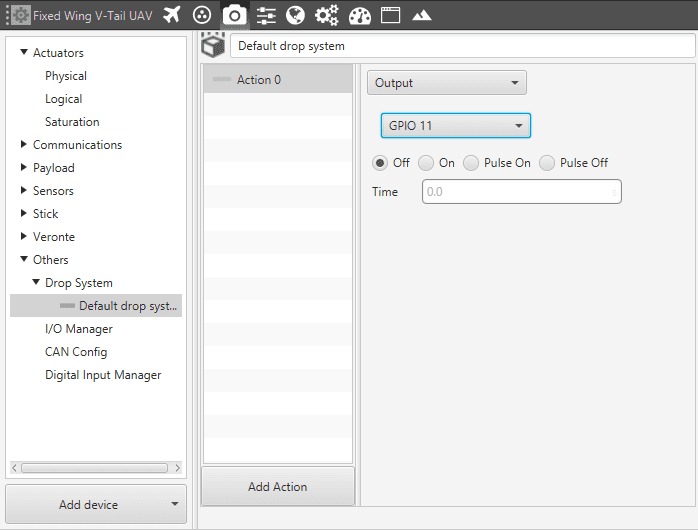
Capsule Dropping device
It is possible to create a Drop System before the mission and select it after, this can be done at the Devices panel.