Pitching
The following program is used to define the behavior and control of the aircraft to perform Pitch. The design of the program is made according to the flight phase, dividing the program into three groups of phases where the design of the control laws are similar.
Standby, Armed, Flight Control Check, Init
In these flight phases, the aircraft does not require any design laws for pitch control since it is not flying.

Take-off, Approach, Landing, Loiter, Hover, Cruise, Climb
Pitch control will depend on the Control mix variable, since the aircraft flight configuration is essential in controlling the aircraft.
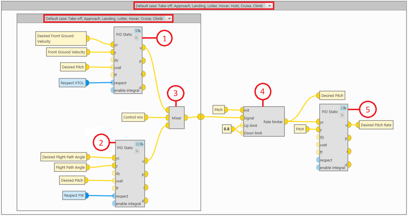
The program is basically controlled by 3 PID controllers, which provide the speed ratio as a function of the input variable and the desired variable.
The PID controller is defined for quadcopter flight configuration.
In the quadcopter configuration, Pitch is performed to be able to control the Front Ground Velocity, so this velocity will be the input variable in the PID controller.

Important
When the Respect VTOL bit (set in the Control Mix program) is true, the u output of the PID block is equal to the usat input. That is, when the bit is true, the output of the PID block will be the output variable of the Rate limiter block, Desired Pitch.
The PID controller is defined for the FW flight configuration.
In FW configuration, Pitch is performed to control the Flight Path Angle, so this variable will be the input variable in the PID controller.
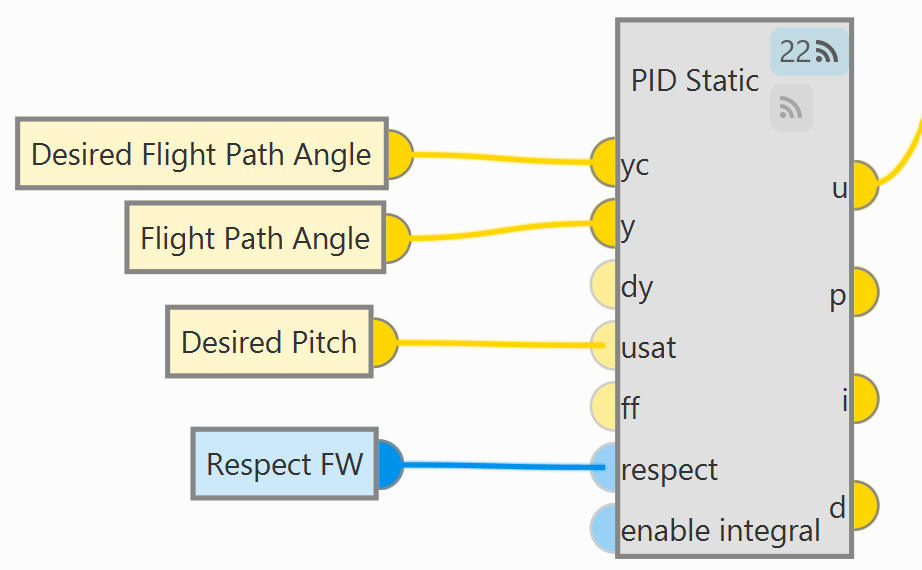
Important
When the Respect FW bit (set in the Control Mix program) is true, the u output of the PID block is equal to the usat input. That is, when the bit is true, the output of the PID block will be the output variable of the Rate limiter block, Desired Pitch.
Mixer block provides the output signals of the above PID controllers depending on the Control mix variable.
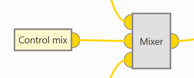
Mixer block is a custom program located in the Library.
Mixer block - Explanation
Mixer block implements the following relationship between input variables and output variables.
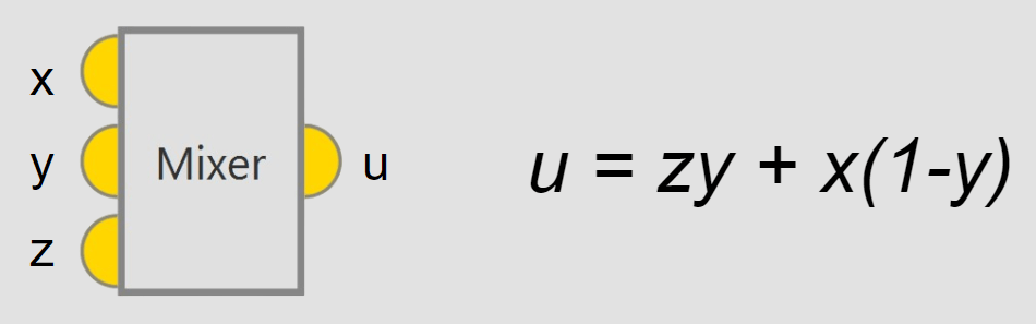
For more information on custom blocks, visit the Library blocks - Block Programs section of the 1x PDI Builder user manual.
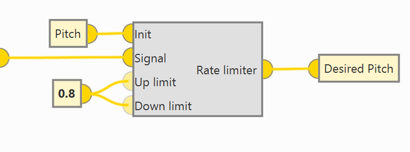
The Rate limiter block is defined to adjust the input signal to a controlled gain.
This block limits the rate of change of the variable by limiting the rate of rise and fall of the variable. The purpose is to achieve a controlled rate of change that allows safe operation of the aircraft.
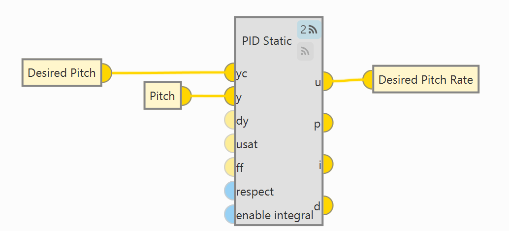
A PID controller is defined giving the Desired Pitch Rate.
Hold
In this flight phase, the output of the PID controller is the Desired Pitch Rate. Since this flight phase is intended to keep the aircraft attitude constant, no PID controller is defined to provide a rate of change.
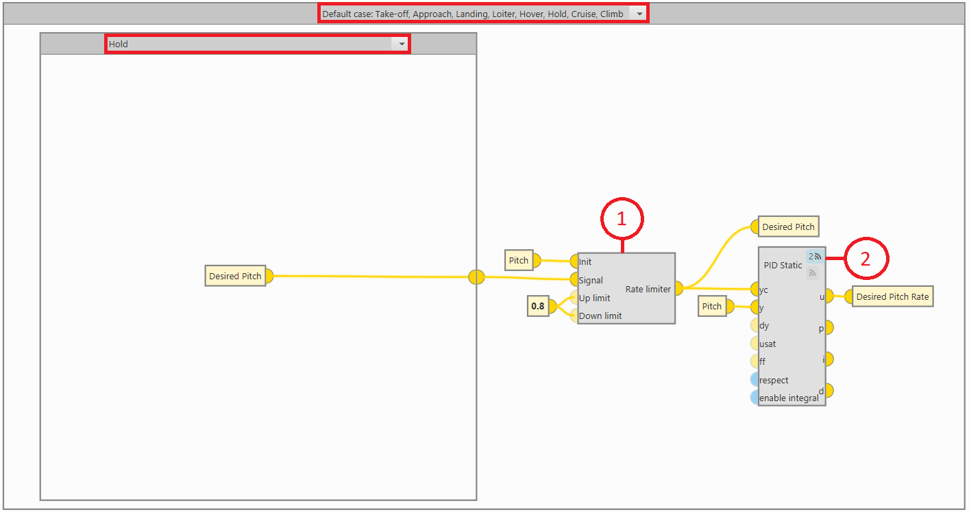
The Rate limiter block is defined to adjust the input signal to a controlled gain.
This block limits the rate of change of the variable by limiting the rate of rise and fall of the variable. The objective is to achieve a controlled rate of change that allows safe operation of the aircraft.
The Signal input variable of the Rate limiter block, Desired Pitch, is generated by the Guidance program. In the Hold flight phase it is intended to stabilize the aircraft attitude, that is why the Desired Pitch control is independent of the flight configuration.
A PID controller is defined giving the Desired Pitch Rate variable.