Sensors
The configuration of the different sensors used for autopilot navigation is explained below.
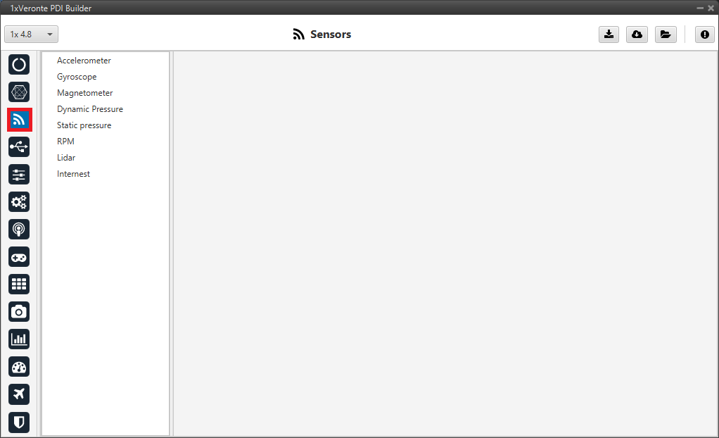
Sensors Panel
Veronte Autopilot 1x incorporates 3 Inertial Measurement Units (IMUs) that allow the 1x system to measure different variables and that are the main source of navigation data.
Accelerometer
Note
For a detailed explanation of the available accelerometer sensors, please visit the Accelerometer - Sensors section of the 1x PDI Builder user manual.
The accelerometer from the IMU can be configured as explained in the panels shown below.
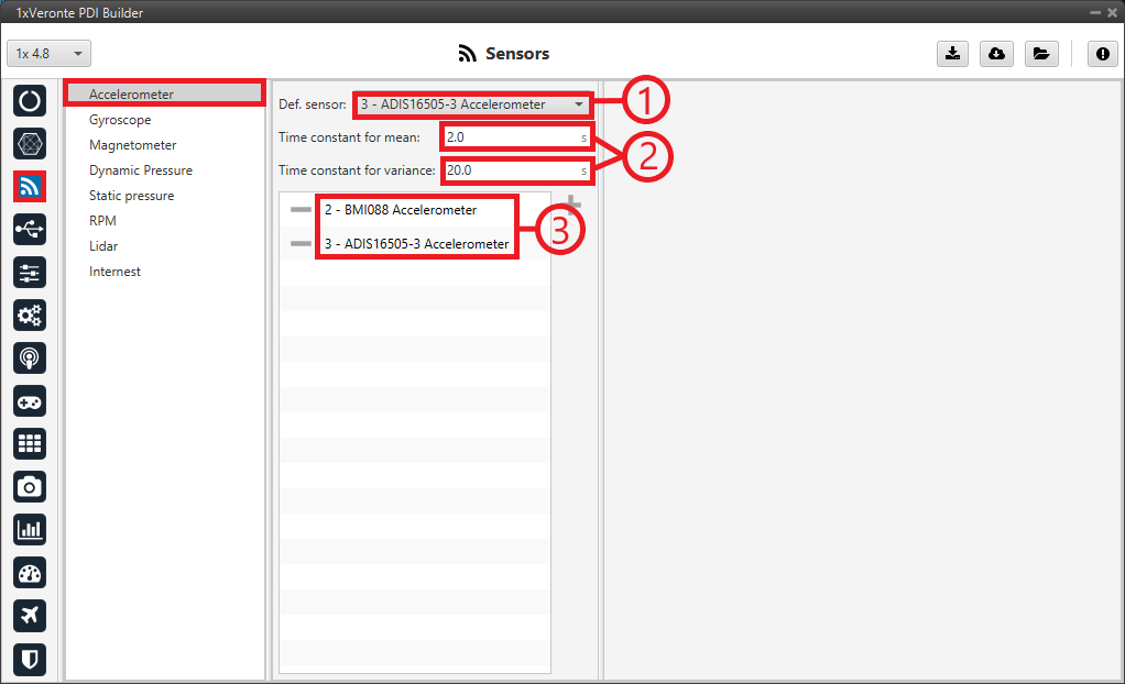
Accelerometer Panel
Important
It is recommended to select multiple of these sensors for the navigation algorithm, so that Veronte Autopilot 1x performs a combination of all the measurements of the selected accelerometers.
This combination consists of calculating the means and variances of each of these accelerometers in a given time (Time constant for mean and Time constant for variance) to obtain a weighted mean with the inverse of the variance. The lower the variance, the greater the weight of that sensor in the mean.
The ADIS16505-3 Accelerometer sensor has been chosen as the default sensor. If all other sensors fail, the measurement value will be that of the default sensor.
A time of 2 seconds has been defined for the Time constant for mean, and 20 seconds for the Time constant for variance.
The BMI088 and ADIS16505-3 accelerometers sensors have been selected and their configuration is described below.
Common configuration of BMI088 Accelerometer and ADIS16505-3 Accelerometer
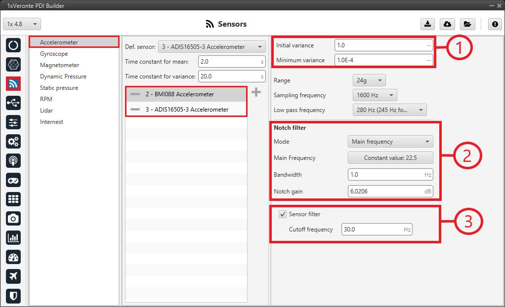
Common configuration
Initial variance = 1.0
Minimum variance = 1.0E-4
Notch filter: It is a filter that dampens signals only at a specific frequency.
Mode: Main frequency
Main Frequency: 22.5
Bandwidth: 1.0 Hz
Notch gain: 6.0206 dB
Sensor filter: Enabled.
Cutoff frequency: 30.0 Hz
BMI088 Accelerometer
This panel displays the possible parameters that can be configured for the internal BMI088 Accelerometer.
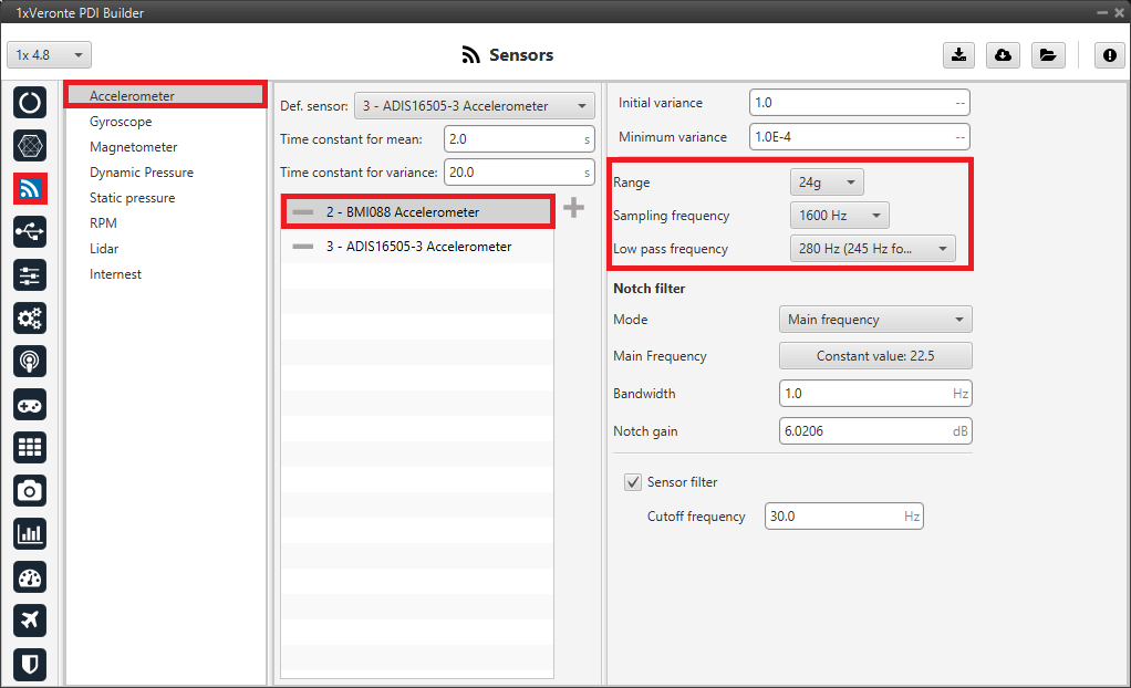
BMI088 Accelerometer Panel
Range: We select a high range of forces that the accelerometer can measure. The lowest accuracy is accepted so that the system does not saturate.
Sampling frequency: That is the frequency at which the measurements are read out. We recommend the highest (1600Hz).
Low pass frequency: The cutoff frequency is set to 280Hz (245 Hz for the Z axis).
ADIS16505-3 Accelerometer
This panel displays the possible parameters that can be configured for the internal ADIS16505-3 Accelerometer.
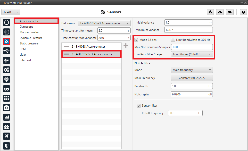
ADIS16505-3 Accelerometer Panel
Mode 32 bits: Following the recommendation, we enable it.
Limit bandwith to 370Hz: Following the recommendation, we disable it.
Max Non-variation Samples: This is configured manually.
Low Pass Filter Stages: Following the recommendation, 4 stages (Cutoff f=40Hz) are configured.
Gyroscope
Note
For a detailed explanation of the available gyroscope sensors, please visit the Gyroscope - Sensors section of the 1x PDI Builder user manual.
The gyroscope from the IMU can be configured as explained in the panels shown below.
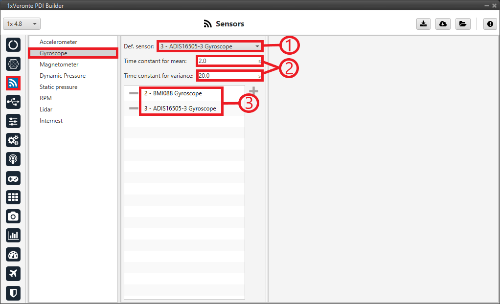
Gyroscope Panel
Important
It is recommended to select multiple of these sensors for the navigation algorithm, so that Veronte Autopilot 1x performs a combination of all the measurements of the selected gyroscopes.
This combination consists of calculating the means and variances of each of these gyroscopes in a given time (Time constant for mean and Time constant for variance) to obtain a weighted mean with the inverse of the variance. The lower the variance, the greater the weight of that sensor in the mean.
The ADIS16505-3 Gyroscope sensor has been chosen as the default sensor. If all other sensors fail, the measurement value will be that of the default sensor.
A time of 2 seconds has been defined for the Time constant for mean, and 20 seconds for the Time constant for variance.
The BMI088 and ADIS16505-3 gyroscopes sensors have been selected and their configuration is described below.
Common configuration of BMI088 Gyroscope and ADIS16505-3 Gyroscope
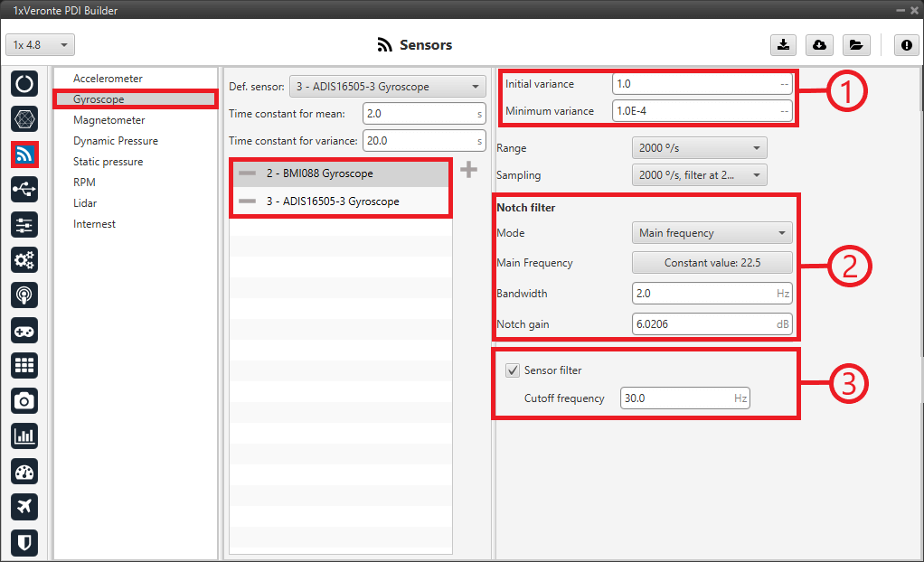
Common configuration
1. Initial variance = 1.0 Minimum variance = 1.0E-4
Notch filter: It is a filter that dampens signals only at a specific frequency.
Mode: Main frequency
Main Frequency: 22.5
Bandwidth: 1.0 Hz
Notch gain: 6.0206 dB
Sensor filter: Enabled.
Cutoff frequency: 30.0 Hz
BMI088 Gyroscope
This panel displays the possible parameters that can be configured for the internal BMI088 Gyroscope.
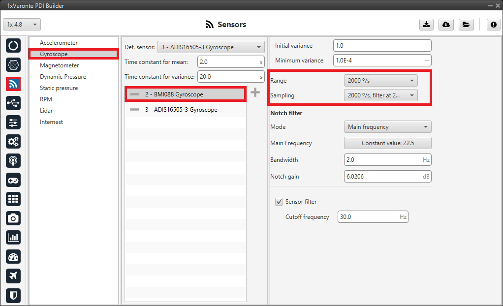
BMI088 Gyroscope Panel
Range: We select a high performance range, 2000°/s.. The lower accuracy is accepted so that the system does not saturate.
Sampling: The angular velocity is set to 2000°/s filter at 230 Hz.
ADIS16505-3 Gyroscope
This panel displays the possible parameters that can be configured for the internal ADIS16505-3 Gyroscope.
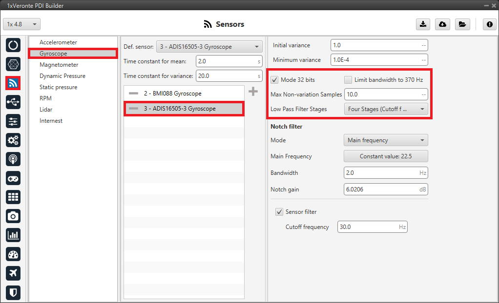
ADIS16505-3 Gyroscope Panel
Mode 32 bits: Following the recommendation, we enable it.
Limit bandwith to 370Hz: Following the recommendation, we disable it.
Max Non-variation Samples: This is configured manually.
Low Pass Filter Stages: Following the recommendation, 4 stages (Cutoff f=40Hz) are configured.
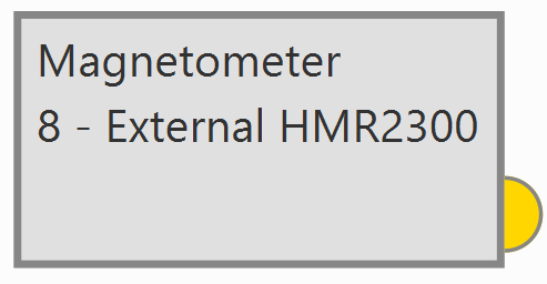
Magnetometer
It is not necessary to configure the magnetometer in this section. It is selected directly in the Navigation program - Block programs.
Dynamic Pressure
The Internal channel has been selected. In this case the Autopilot 1x uses a value provided by the internal sensor.
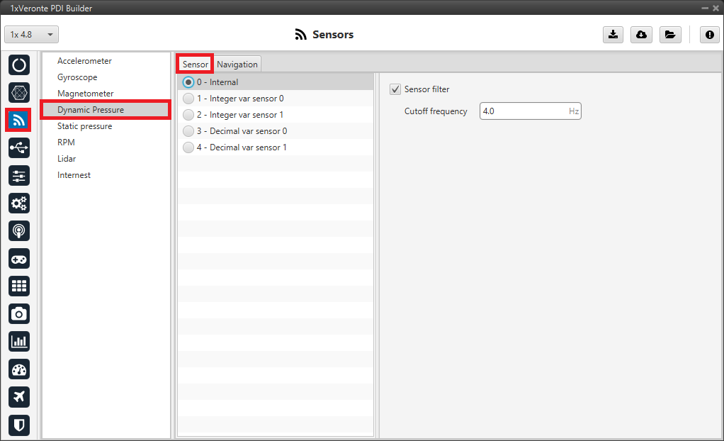
Sensor panel - Dynamic Pressure
A cutoff frequency of 1.0 Hz has been defined in the Sensor panel for the low pass filter. It is necessary to enable the sensor filter to be able to define the cutoff frequency.
The image below shows a basic configuration of the Navigation panel.
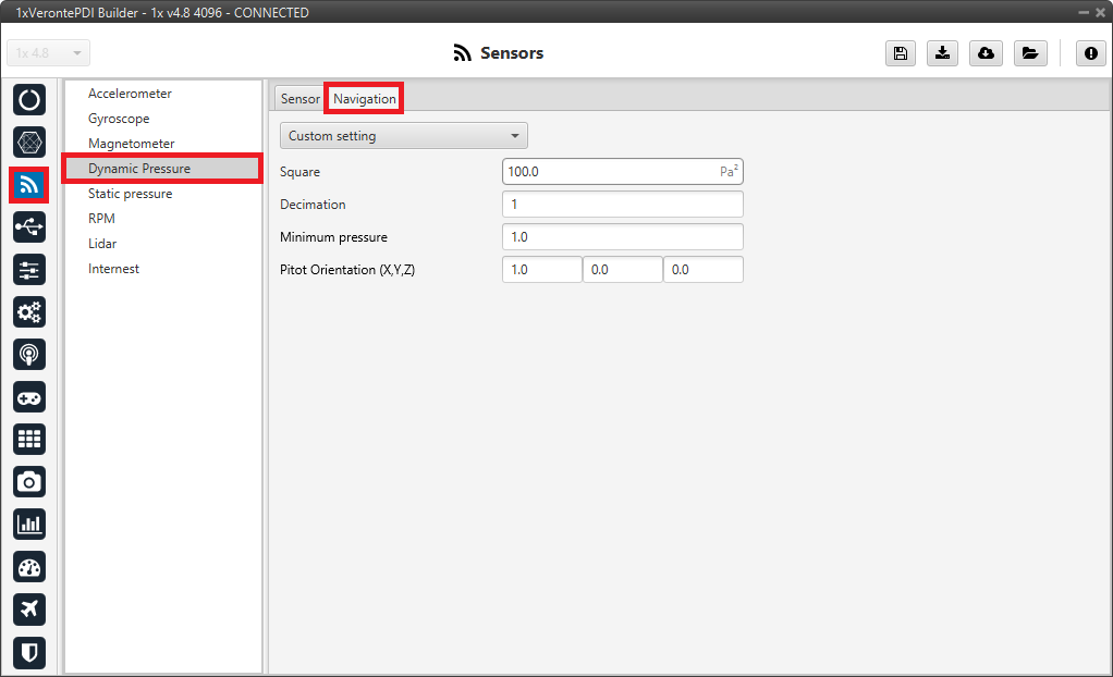
Navigation panel - Dynamic Pressure
Note
For a detailed explanation of the available dynamic pressure sensors, please visit the Dynamic Pressure - Sensors section of the 1x PDI Builder user manual.
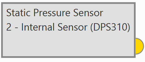
Static Pressure
It is not necessary to configure the Static Pressure sensor in this section. It is selected directly in the Navigation program - Block programs.