Antenna Kit A - Parabolic 2.4 GHz
Mount the omnidirectional antenna reading the Omnidirectional Antenna section.
Screw the splitter to the antenna mount with two screws M3 x 30 mm.
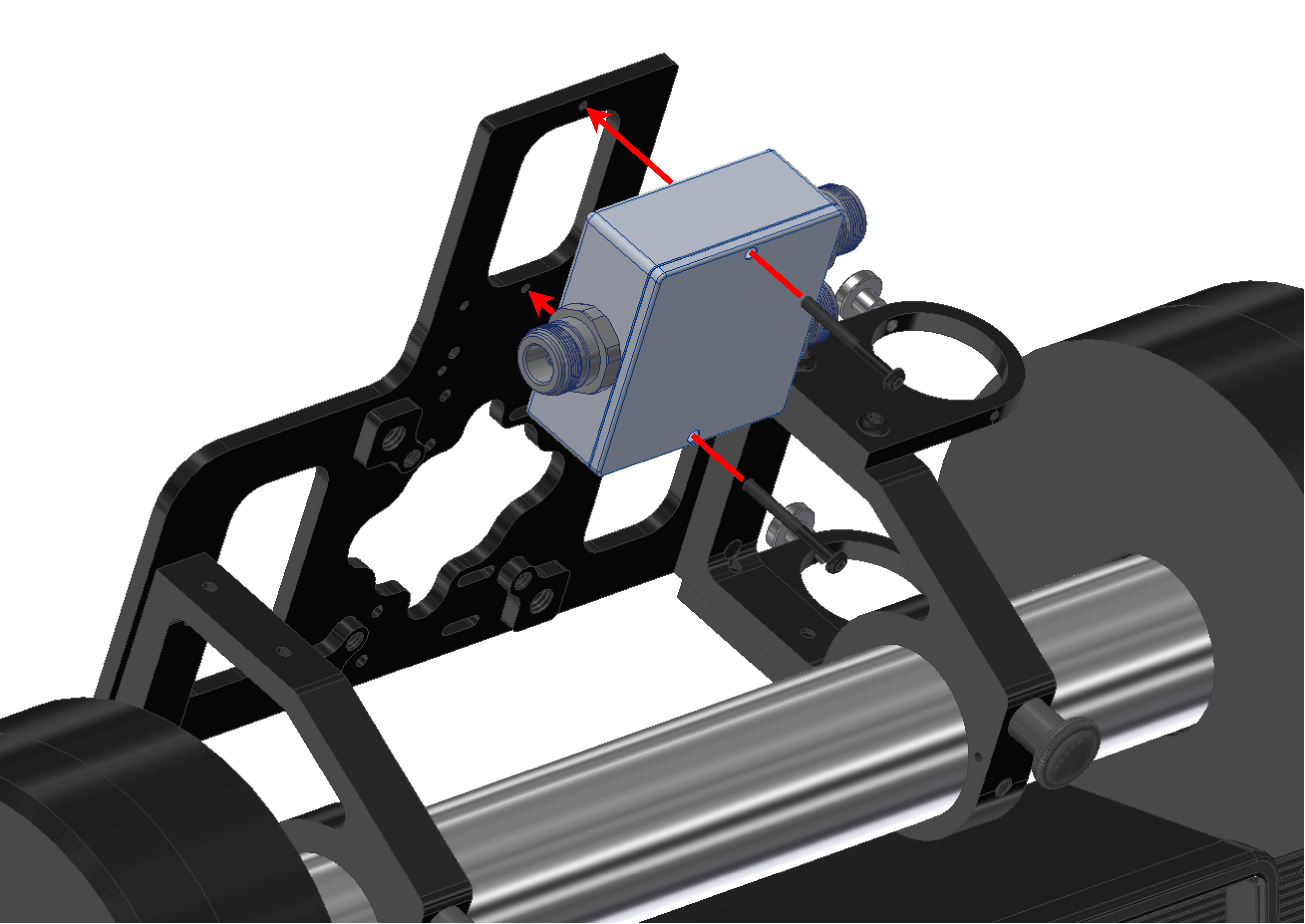
Note
The splitter receives an electrical signal and sends it to two different antennas.
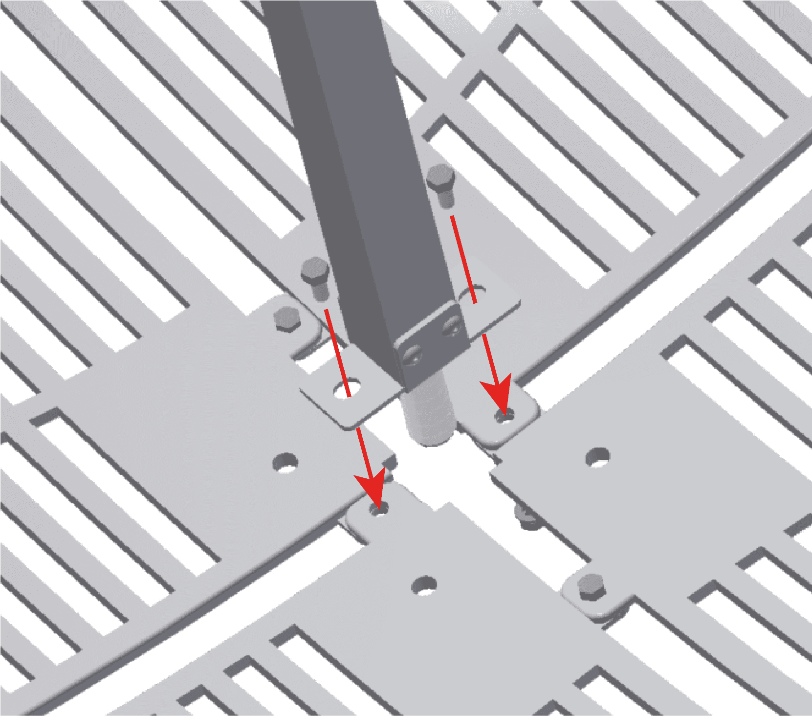
Fit the 4 grids with the protrusions.
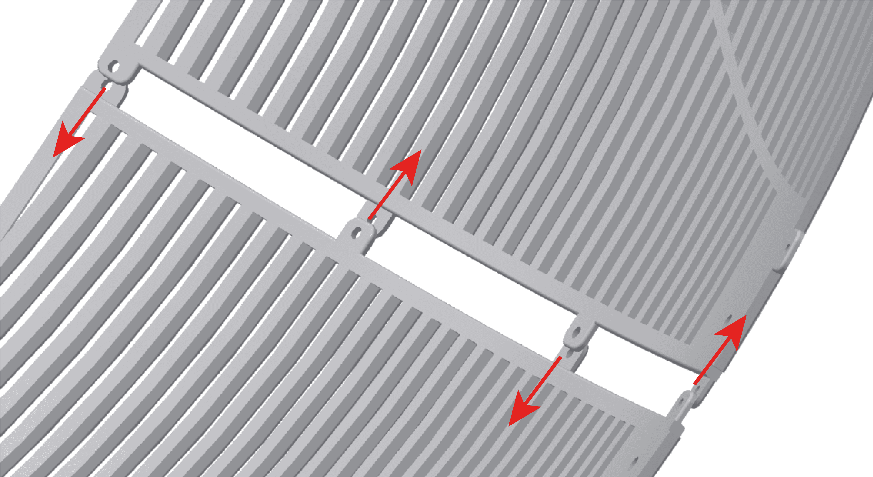
They must fit as next figure indicates:
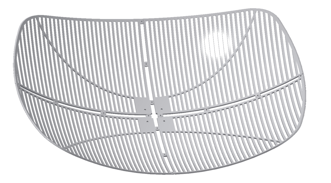
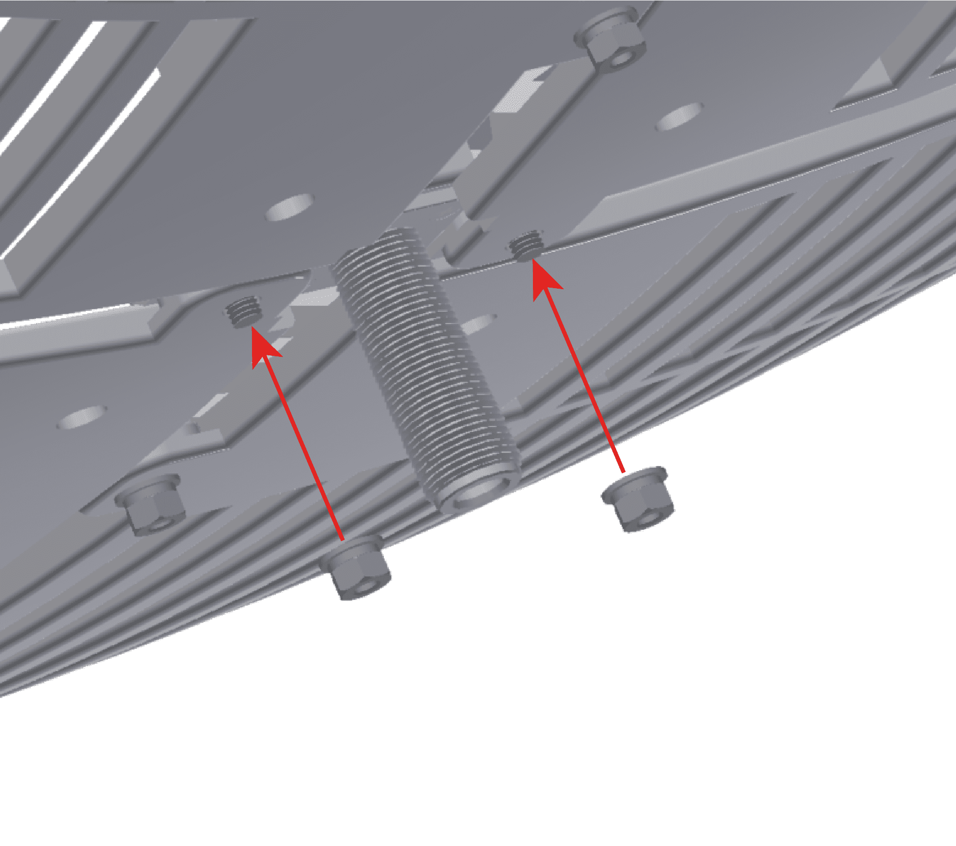
Screw the 4 pieces with twelve screws M5x15 and their corresponding nuts.
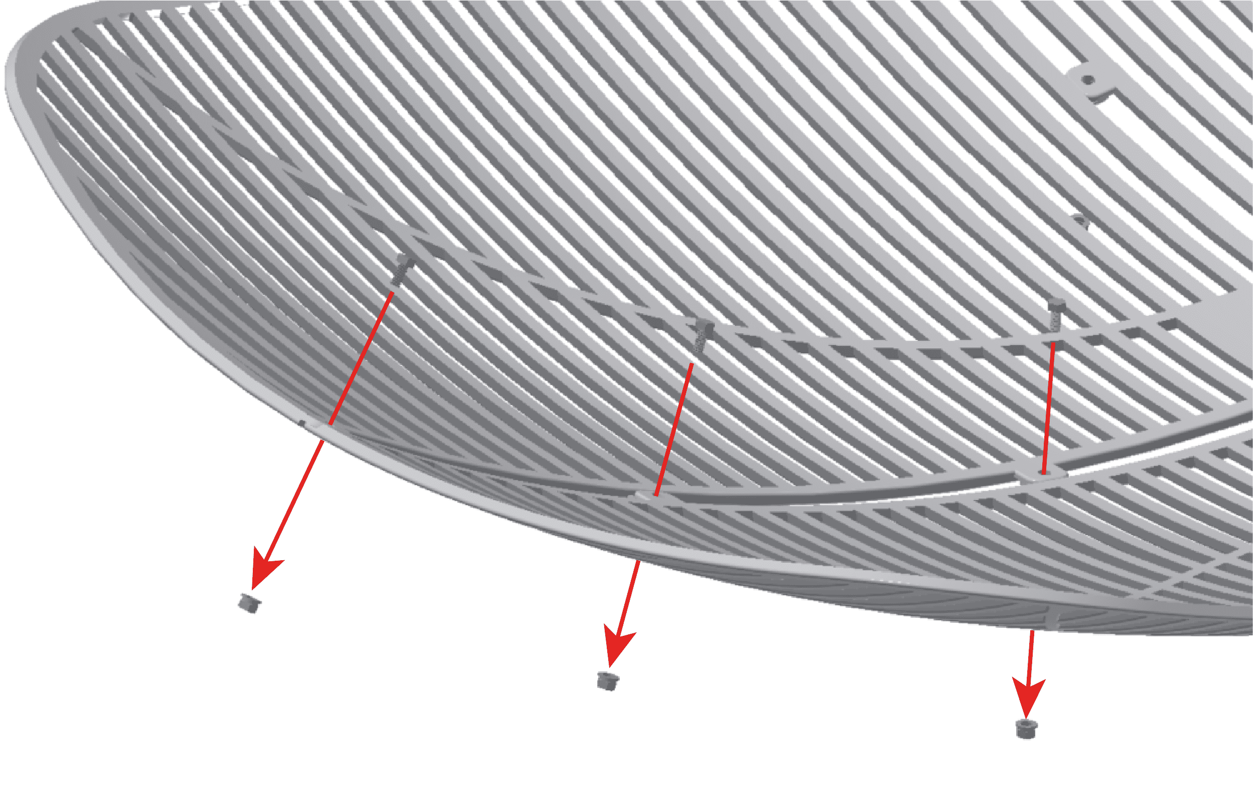
Screwing one of four sides
Screw the horn to the grids with two screws M5x15 and their corresponding nuts.
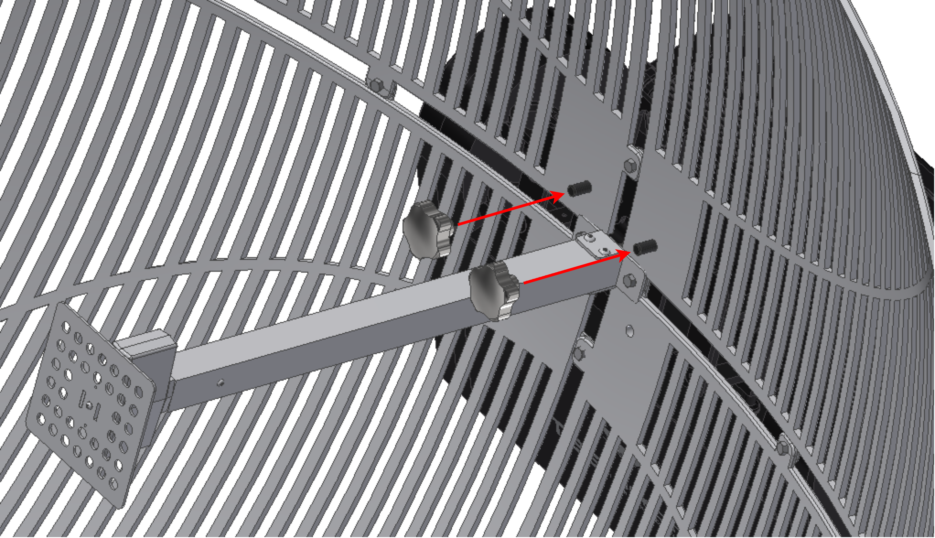
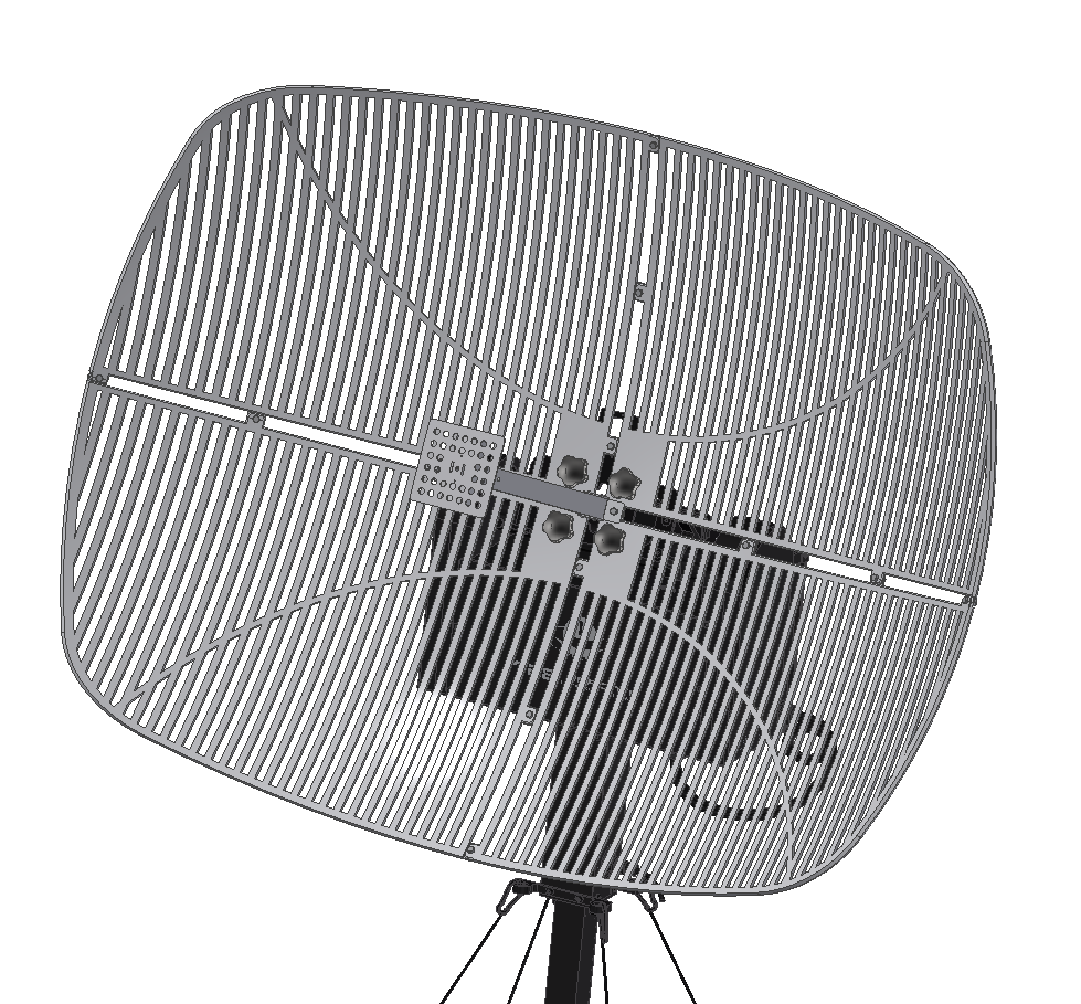
6. Place the parabollic antenna on the T28, so the two upper screws on the T28 are inserted into the antenna. It can be placed with 90 degrees angle in case of desiring to change the polarity direction. This direction is indicated by an arrow on the antenna.
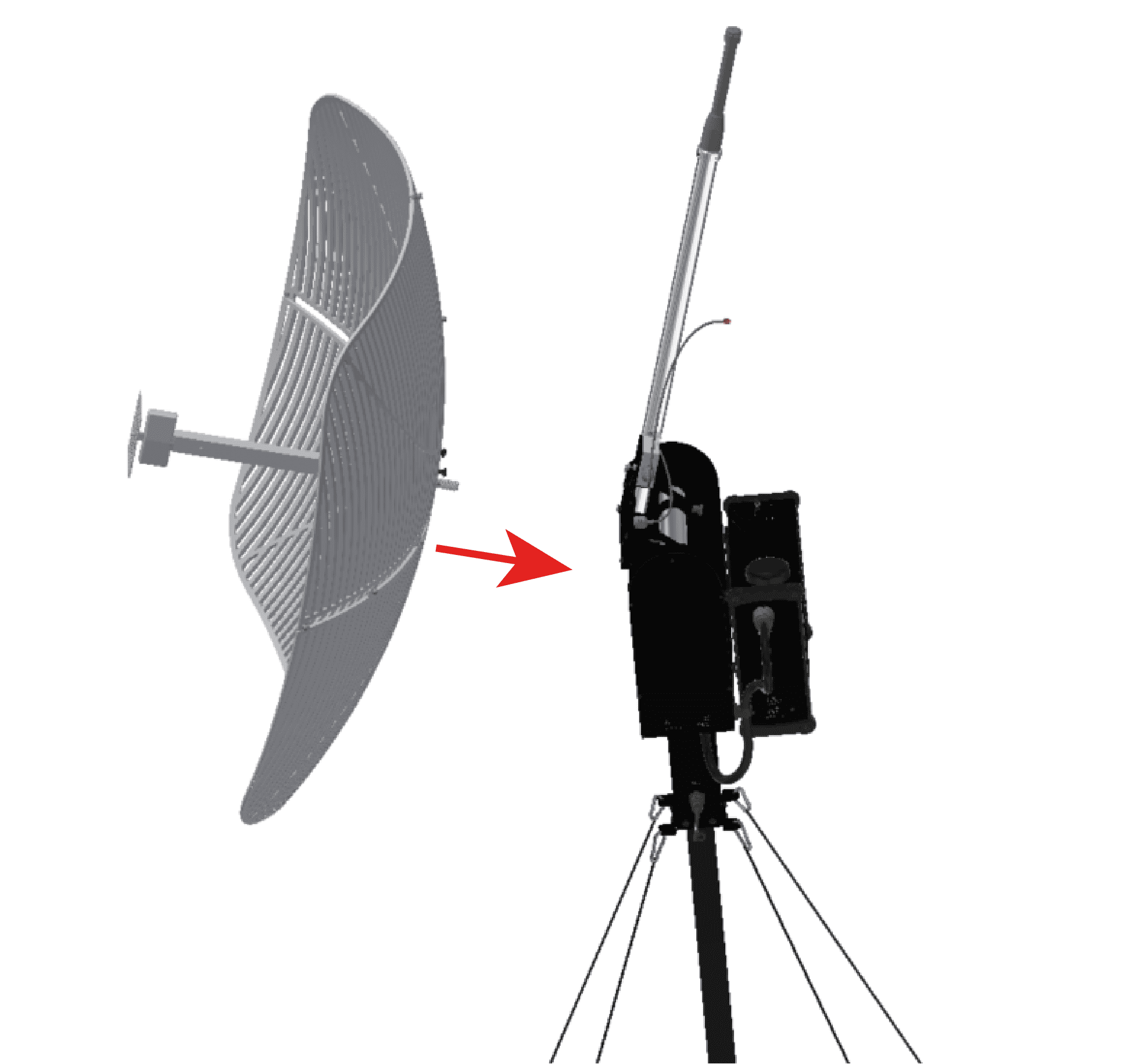
Placing antenna
Fitting antenna
Turned 90 degrees
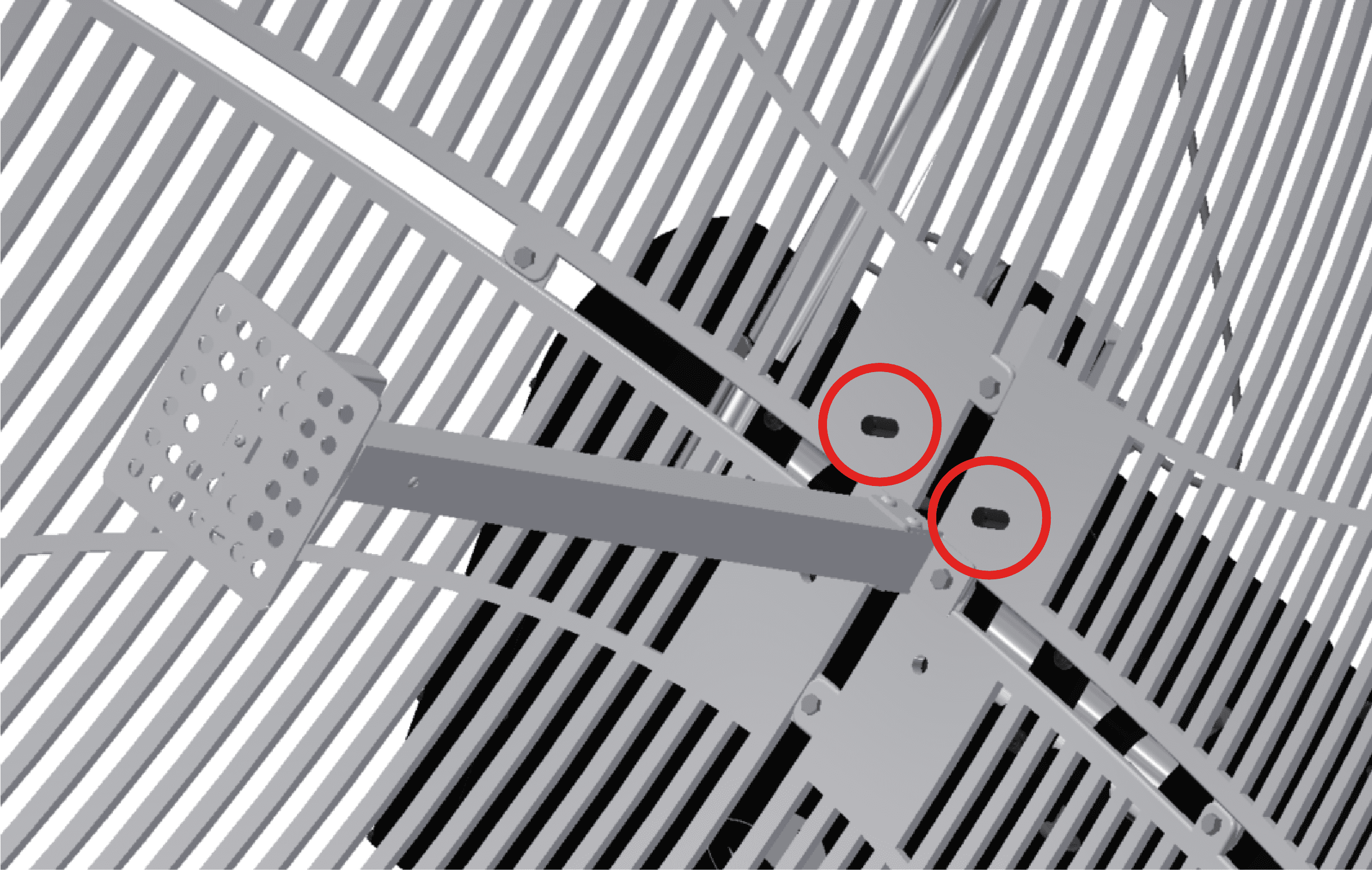
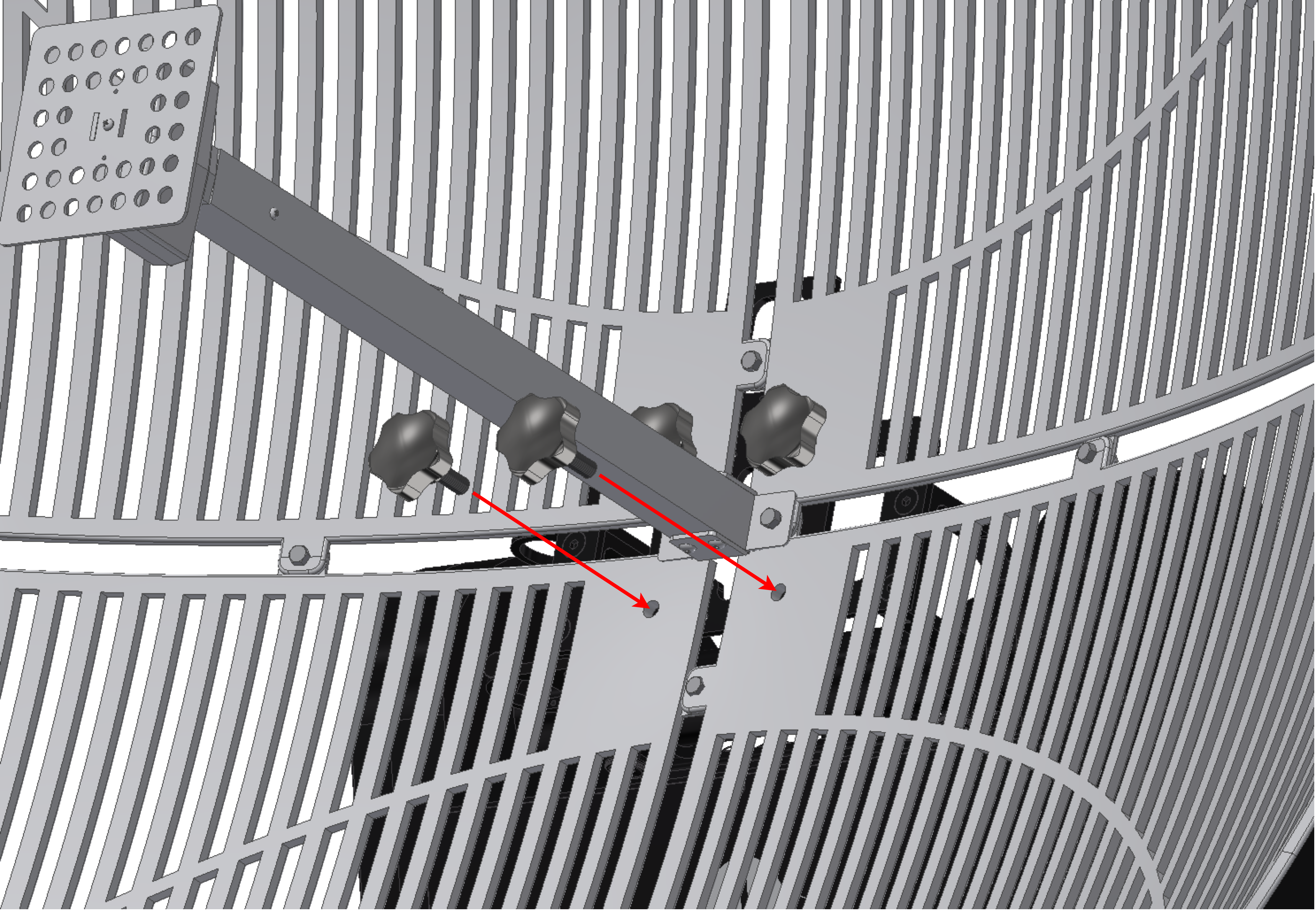
Fix the Parabolic Grid Antenna with the two female knobs.
Screw two male knobs on the other two holes.
Connect each plug of the splitter.
1 |
Port RF2 of PCS |
2 |
Omnidirectional antenna |
3 |
Parabolic antenna |