Integration examples
CAN communication
MEX can send and receive messages via CAN.
CAN messages transmission
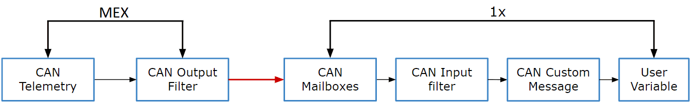
CAN messages transmission - Communication diagram MEX \(\rightarrow\) 1x
Users must follow the steps below to send telemetry via CAN and configure an Autopilot 1x to read this telemetry.
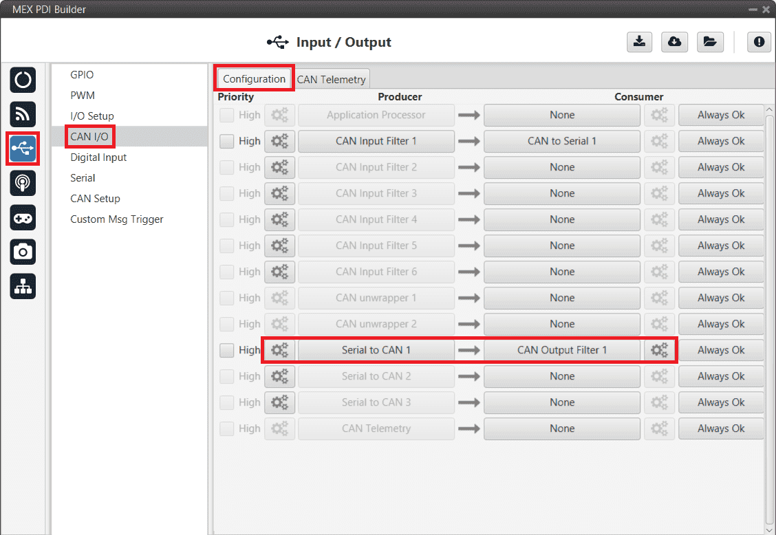
Go to Input/Output menu \(\rightarrow\) CAN I/O panel \(\rightarrow\) Configuration tab.
Connect CAN Telemetry to a CAN Output Filter as follows:
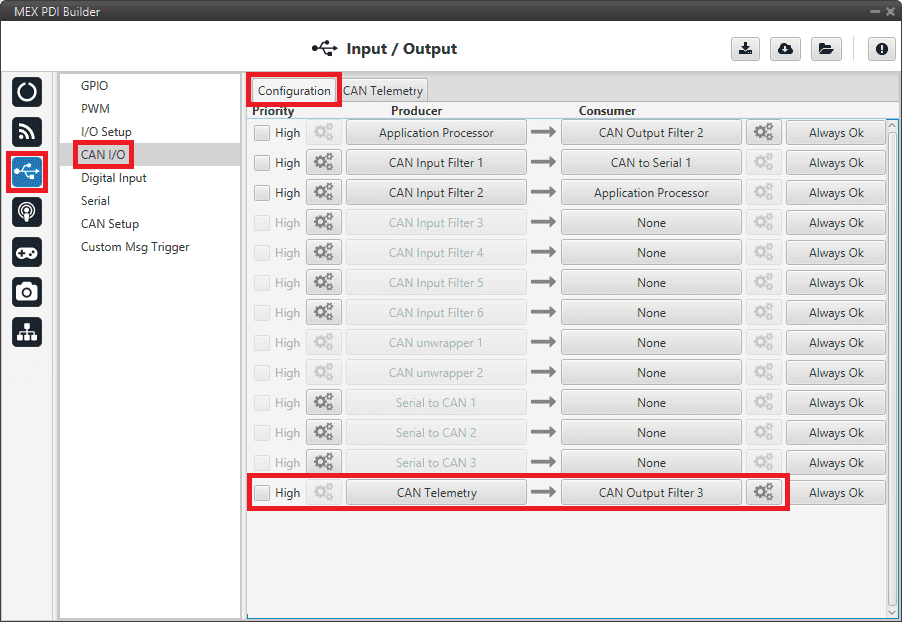
CAN messages transmission - CAN I/O configuration
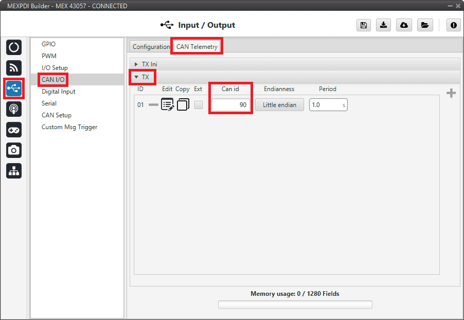
Go to Input/Output menu \(\rightarrow\) CAN I/O panel \(\rightarrow\) CAN Telemetry tab.
Select the fields to send in the TX. More information about the configuration of telemetry messages can be found in the CAN Telemetry - Input/Output section of this manual.
CAN messages transmission - CAN Telemetry
For example, a telemetry message with a variable set to ID 90:
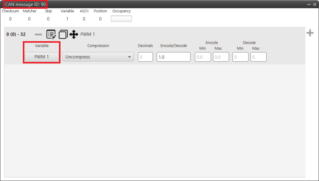
CAN messages transmission - CAN Telemetry example
Configure the Autopilot 1x to read telemetry from MEX, following the CAN messages reception - Integration examples section of the 1x PDI Builder user manual.
Note
The configured CAN ID must match the one in MEX.
CAN messages reception

CAN messages reception - Communication diagram
Users must follow the steps below to read CAN messages.
Go to Input/Output menu \(\rightarrow\) CAN I/O panel \(\rightarrow\) Configuration tab.
Connect a CAN Input Filter to a CAN serial wrapper as follows:
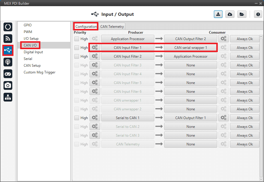
CAN messages reception - CAN I/O configuration
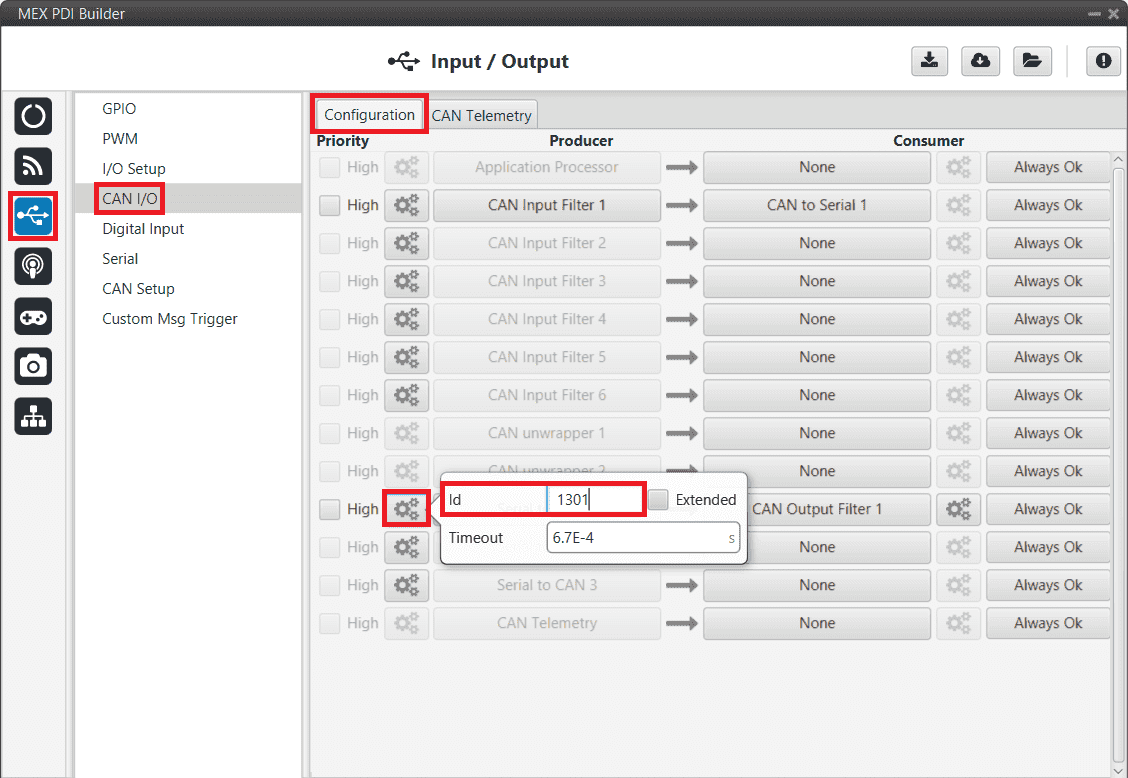
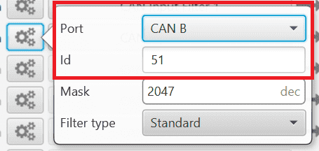
Click on the
 button of the CAN Input Filter and configure the Port and CAN Id, according to the messages to receive.
Go to Input/Output menu \(\rightarrow\) I/O Setup panel \(\rightarrow\) Configuration tab.
Connect the corresponding CAN wrapper for serial transmission to a Custom message consumer.
Note
The CAN wrapper for serial transmission index must match the index of the CAN serial wrapper configured in the previous step (in this example, CAN wrapper for serial transmission with index 1 is used).
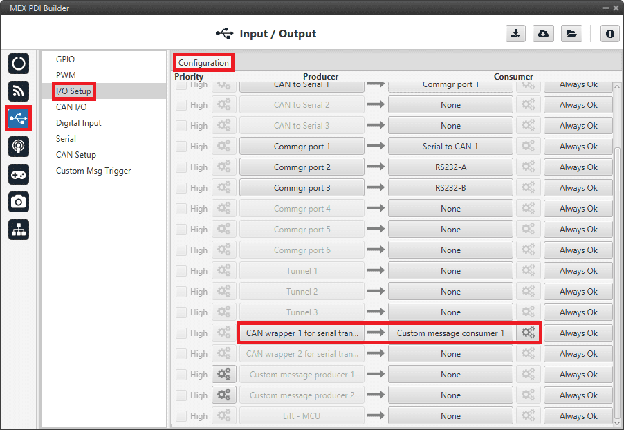
CAN messages reception - I/O Setup configuration
Click on the
button of the Custom message consumer to access its configuration. To correctly read the CAN message, it must be setup as follows:Endianness: Little endian
Matcher:
Value: 202
Bits: 8
Skip 40
User variables to receive.
CRC:
Type: Polynomial
Endianness: Little endian
Crc-Preset: crc16veronte
BackFrom: Number of bytes from which the CRC is computed, in this case, bytes comprehended between the Matcher and this CRC.
BackTo: 0
Binary mode
If users wish more detailed information on this configuration, please refer to Custom message types - Input/Output section of the 1x PDI Builder user manual.
The configuration of the Custom message consumer below is an example of the reception of three Real variables.
Note
The CRC BackFrom entry is 17 since there are 5 bytes in the Skip 40 and 12 bytes for the User variables.
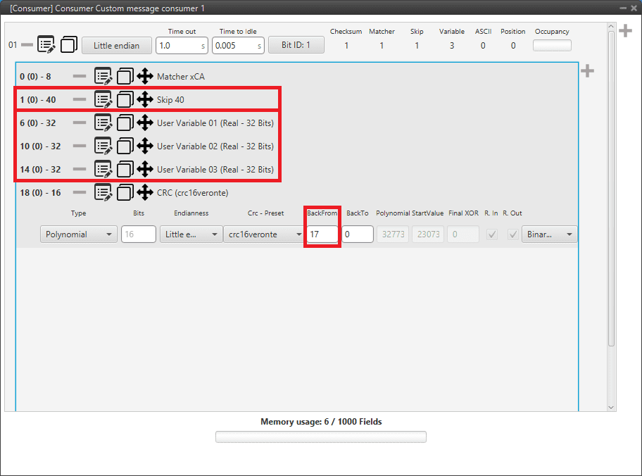
CAN messages reception - Custom message configuration example
CAN Isolator
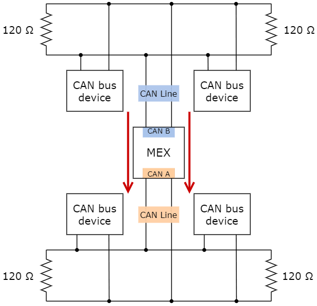
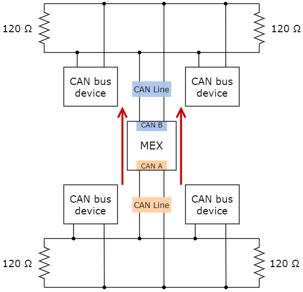
MEX can operate as a CAN bus isolator, since it manages both CAN buses as desired. The system has a built-in microcontroller; which manages CAN buses in real-time. Both buses are not electrically connected, in consequence, electrical signals that do not follow the CAN protocol will be isolated.
The functionalities of a CAN isolator are the following:
The following diagram summarizes the behavior of MEX as a CAN bus isolator:
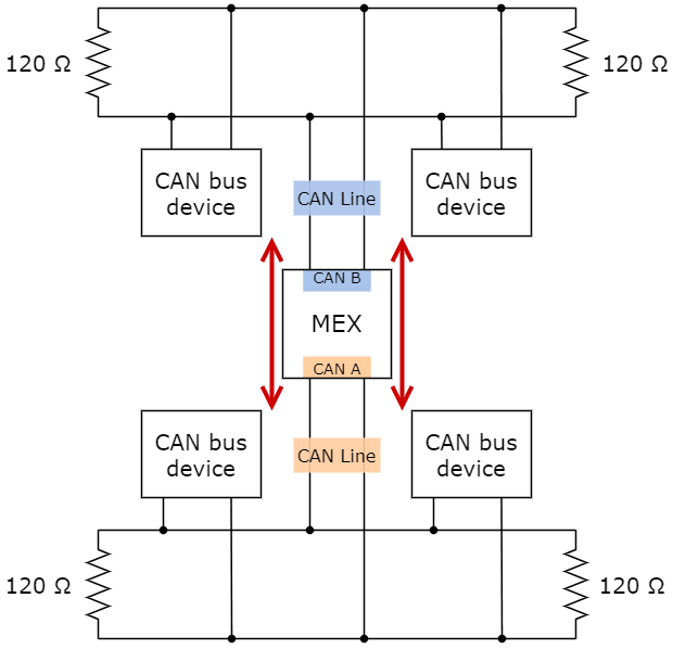
Subnets CAN diagram
Filtered CAN subnet
With MEX it is possible to isolate CAN nets, by filtering certain messages from one CAN line and only transmitting specific information through MEX to the other one.
In this example, only a certain range of CAN IDs will be allowed to cross from one CAN line to the other using the two CAN ports of MEX. Specifically, information will pass from CAN B of MEX to CAN A of MEX:
Subnets CAN example - From CAN B to CAN A
The allowed range will be from 0x550 to 0x55F.
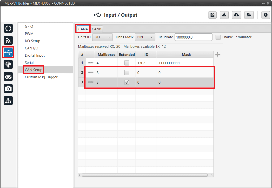
Create a new mailbox entry for CAN B.
To do this, go to Input/Output menu \(\rightarrow\) CAN Setup panel \(\rightarrow\) CAN B tab.
Assign some of the mailboxes to it and set the ID to 0x550. This example uses an ID expressed in hexadecimal notation.
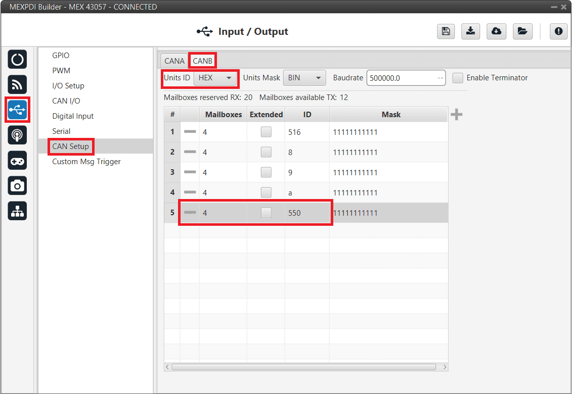
Filtered CAN subnet - CAN Setup configuration
Set a Mask which will ignore the last 4 bits.
Note
Although the ID has been entered in hexadecimal notation, note that the Mask has been set in binary format.
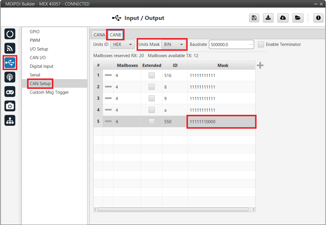
Filtered CAN subnet - CAN Setup mask configuration
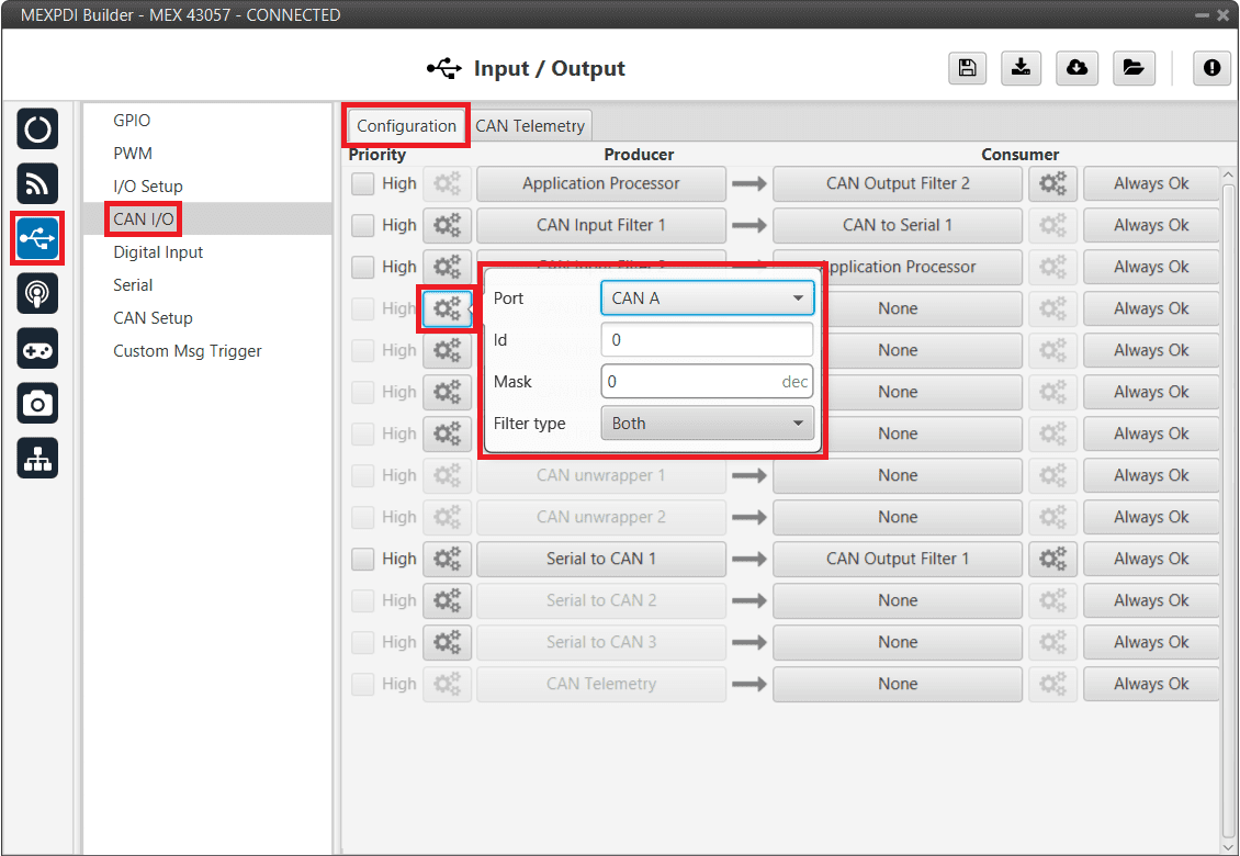
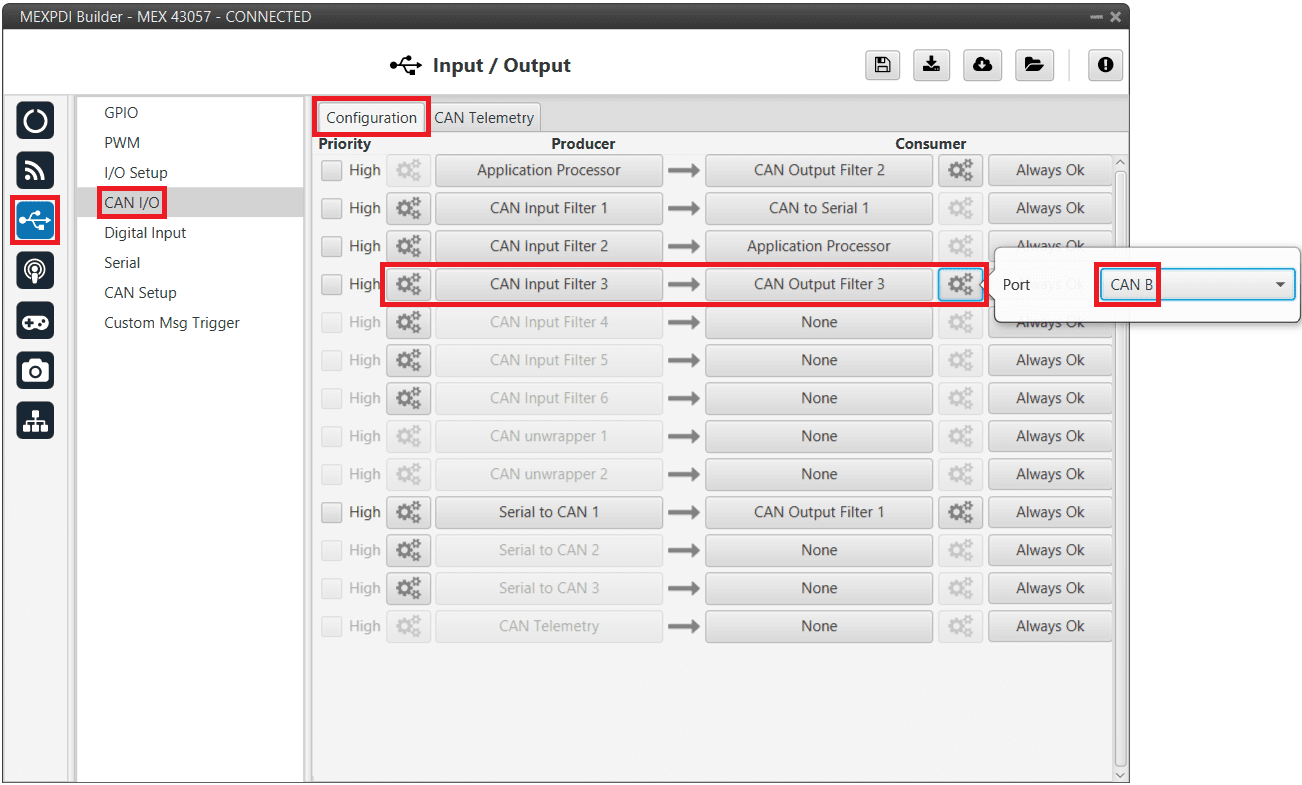
Go to Input/Output menu \(\rightarrow\) CAN I/O panel \(\rightarrow\) Configuration tab.
Configure CAN Input Filter 3 on CAN B, with the same settings as the Mailbox.
Important
This menu only allows setting the Id with decimal numbers. For this example the Id 0x550 is represented as 1360 in decimal format, and the Mask is also represented in decimal format as 2032.
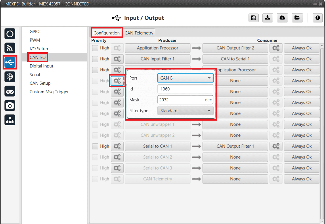
Filtered CAN subnet - CAN Input Filter configuration
Bind CAN Output Filter 3 to CAN Input Filter 3 and, configure the CAN Output Filter to CAN A.
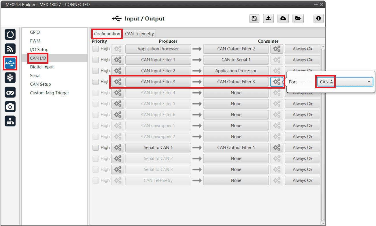
Filtered CAN subnet - CAN Output Filter configuration
CAN tunnel
A CAN tunnel is a specific case of a message tunnel; where messages are tunneled from one CAN port of MEX to the other.
In this example, a transparent tunnel will be created. So, any messages received on Interface A will be sent through Interface B:
Subnets CAN example - From CAN A to CAN B
Optionally, the mailboxes can be equally distributed to support both standard and extended CAN IDs.
Create a new mailbox entry for Interface A.
To do this, go to Input/Output menu \(\rightarrow\) CAN Setup panel \(\rightarrow\) CAN A tab.
Assign half of the mailboxes to it and set a Mask of 0.
CAN tunnel - CAN Setup configuration
Go to Input/Output menu \(\rightarrow\) CAN I/O panel \(\rightarrow\) Configuration tab.
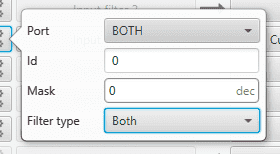
Configure CAN Input Filter 3 on CAN A, with CAN id 0, a Mask of 0 and Both as frame format type.
CAN tunnel - CAN Input Filter configuration
Bind CAN Output Filter 3 to CAN Input Filter 3 and, configure the CAN Output Filter to CAN B.
CAN tunnel - CAN Output Filter configuration
Commanding/Reading PWMs
The appropriate PWM message format is described in Command PWMs - CAN Bus protocol section of the MEX Software Manual.
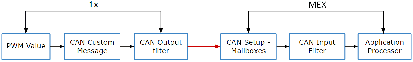
PWM Command - Communication diagram 1x \(\rightarrow\) MEX
The following steps command PWM from Autopilot 1x to MEX:
1x PDI Builder side
Go to Input/Output menu \(\rightarrow\) CAN Setup panel \(\rightarrow\) Configuration tab.
Connect a CAN custom message to an Output filter to send the message:
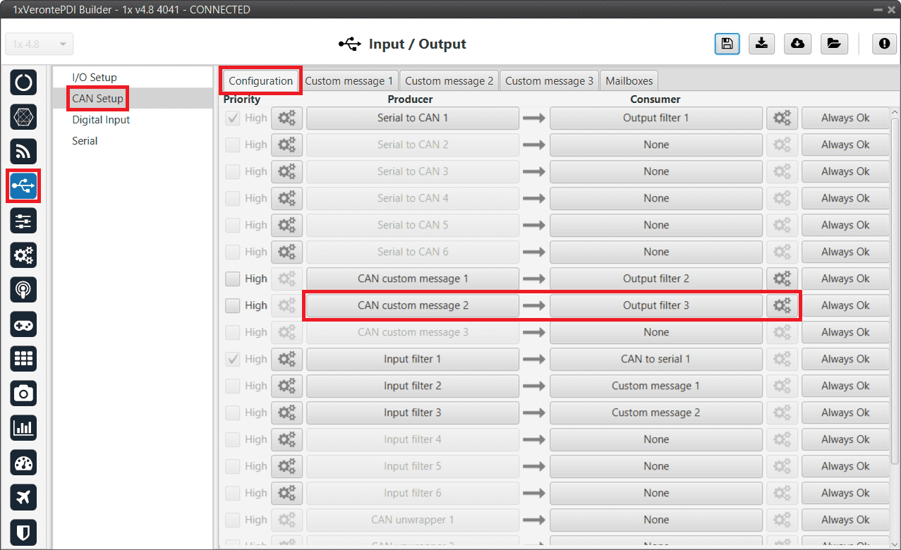
1x PDI Builder - CAN Setup configuration
Go to Input/Output menu \(\rightarrow\) CAN Setup panel \(\rightarrow\) Custom Message 2 tab (because Custom message 2 has been selected as producer).
Build a CAN Custom message using the PWM variable and the appropriate message format. Select the fields to send in the TX as it is a Producer. CAN ID is arbitrary, for this example ID 100 will be used:
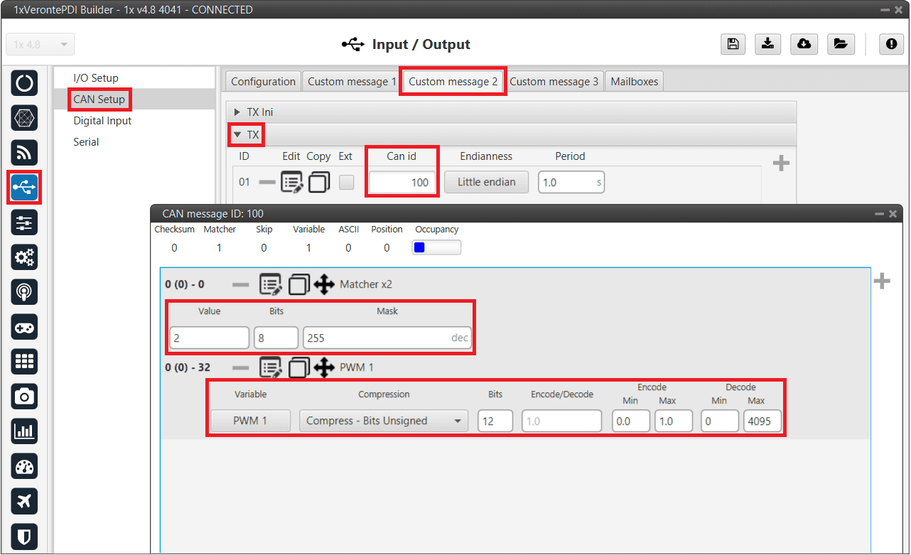
1x PDI Builder - CAN Custom message configuration
Message format:
Matcher (2) [8 bits]
PWM 0 [12 bits]
PWM 1 [12 bits]
PWM 2 [12 bits]
PWM 3 [12 bits]
Matcher (3) [8 bits]
PWM 4 [12 bits]
PWM 5 [12 bits]
PWM 6 [12 bits]
PWM 7 [12 bits]
Each PWM variable has to be set using the following format:
Variable: PWM X
Compression: Compress - Bits Unsigned
Bits: 12
Encode: Min=0.0 / Max=1.0
Decode: Min=0 / Max=4095
MEX PDI Builder side
Go to Input/Output menu \(\rightarrow\) CAN Setup panel.
Create the mailbox to receive the new message (ID 100):
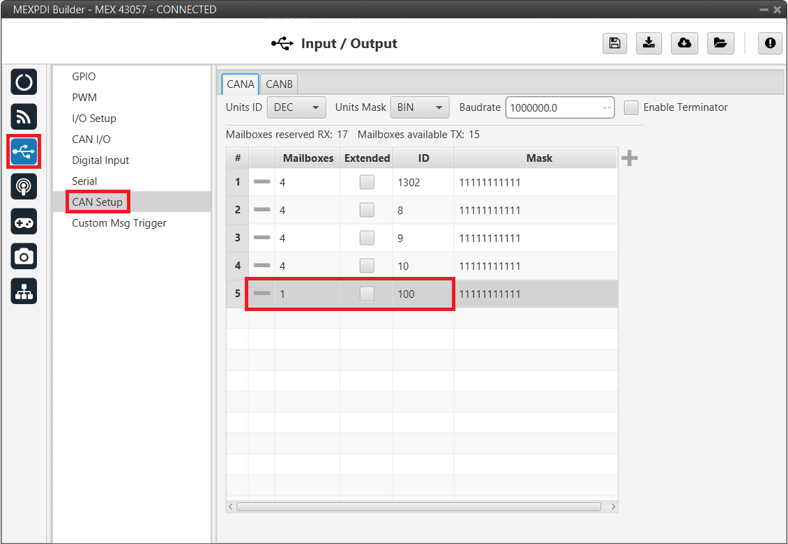
MEX PDI Builder - CAN Setup configuration
Go to Input/Output menu \(\rightarrow\) CAN I/O panel \(\rightarrow\) Configuration tab.
Connect a CAN Input Filter with the right CAN ID to the Application Processor consumer:
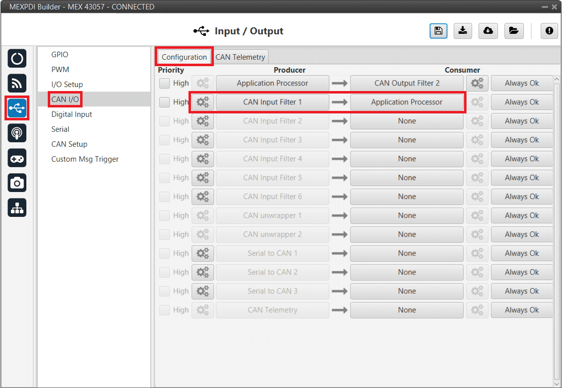
MEX PDI Builder - CAN I/O configuration
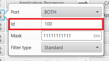
MEX PDI Builder - CAN Input Filter configuration
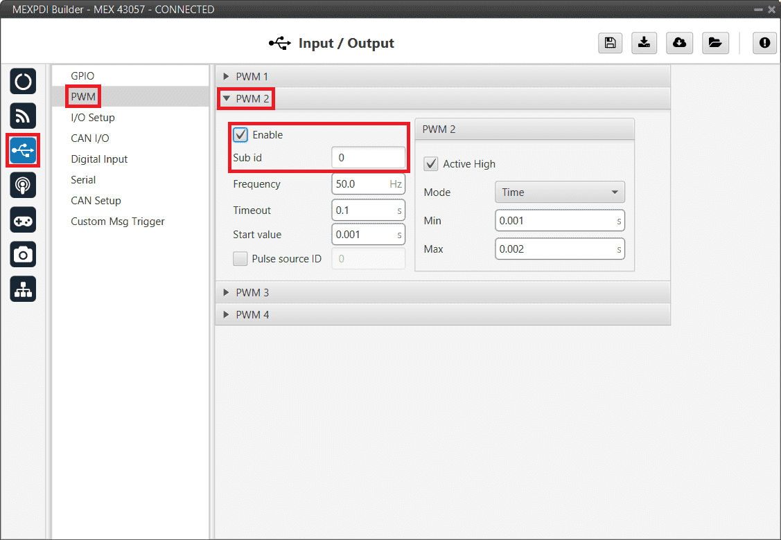
Go to Input/Output menu \(\rightarrow\) PWM panel \(\rightarrow\) PWM 2 tab (as PWM 1 has been selected in 1x PDI Builder).
Note
Check the order of the PWM signal, the first PWM signal of Veronte Autopilot 1x must match the first PWM signal of MEX. Numeration may differ between Veronte applications depending on the used version.
Configure parameters for PWM 2:
MEX PDI Builder - PWM configuration
Go to Input/Output menu \(\rightarrow\) GPIO panel.
Check that this PWM pin (PWM 2 in this case) has correctly switched from GPIO to PWM.
It should look like this:
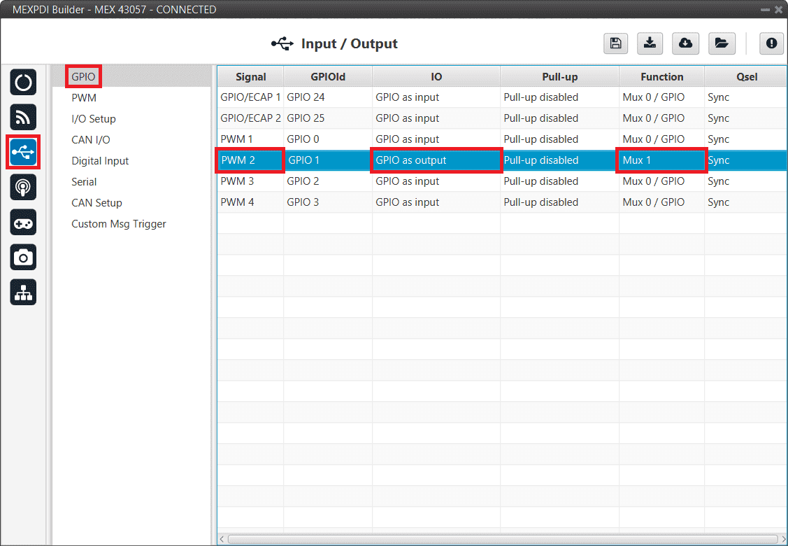
MEX PDI Builder - GPIO configuration
IO: GPIO as output.
Function: Mux 1.
Finally, save changes.
GPIO Command
The following are the steps to send a GPIO command from the Veronte Autopilot 1x, receive it at MEX and process it, so that MEX carries out the command.
GPIO Command is very similar to PWM command with a few differences.
1x PDI Builder side
Go to Input/Output menu \(\rightarrow\) CAN Setup panel \(\rightarrow\) Configuration tab.
Connect, as Producer, a ‘CAN GPIO remote’ to an Output filter:
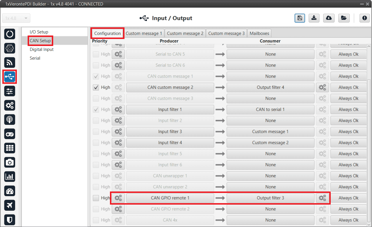
1x PDI Builder - CAN Setup configuration
CAN GPIO remote must be configured. For more information about its configuration, read CAN Setup - Input/Output section of 1x PDI Builder user manual.
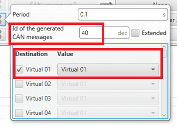
1x PDI Builder - CAN GPIO remote configuration
Go to Automations menu.
GPIO must be activated using an ‘Output’ action:
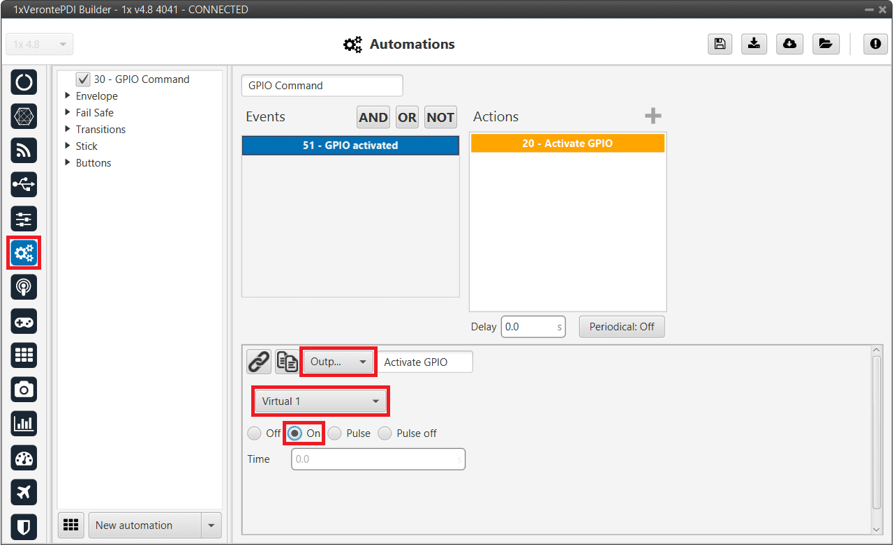
1x PDI Builder - Automation configuration
MEX PDI Builder side
Go to Input/Output menu \(\rightarrow\) CAN I/O panel \(\rightarrow\) Configuration tab.
Finally, connect a CAN Input Filter to the CAN GPIO consumer:
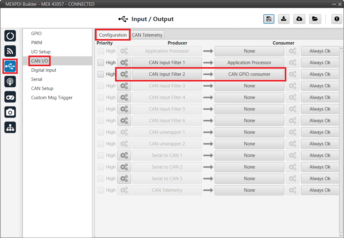
MEX PDI Builder - CAN I/O configuration
The Id must match the one configured in 1x PDI Builder as Output filter:
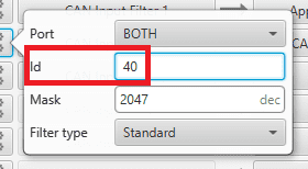
MEX PDI Builder - CAN Input Filter configuration
MEX as external magnetometer Honeywell HMR2300 for Autopilot 1x
MEX has to be configured with MEX PDI Builder to send the magnetometer measurements by messages, in the same way as magnetometer Honeywell HMR2300 does. Autopilot 1x also requires a configuration, which is made with 1x PDI Builder.
This configuration can be done both via Serial or CAN interfaces.
Serial
MEX PDI Builder side
Go to Input/Output menu \(\rightarrow\) I/O Setup panel.
Connect the Custom message producer 1 or 2 to the RS232-A, RS232-B or RS485-C port.
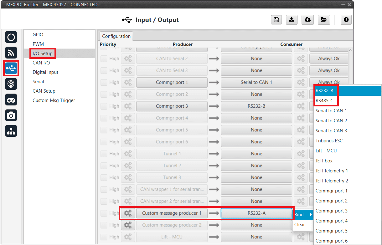
MEX PDI Builder - I/O Setup configuration
Click on the
button of the chosen Custom message producer and add a new message (clicking on  ), then configure it as Big endian and set a Period of 0.02 s.
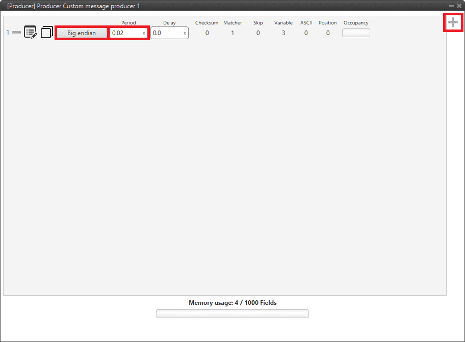
MEX PDI Builder - Custom message configuration
Click on
to add the 3 following Real variables: 313, 314 and 315. Then configure them according to the following table:Parameter
Configuration
Compression
Compress - Bits Signed
Bits
16
Encode
Min: -2.1845334E-4 / Max: 2.1844667E-4
Decode
Min: -32768 / Max: 32767
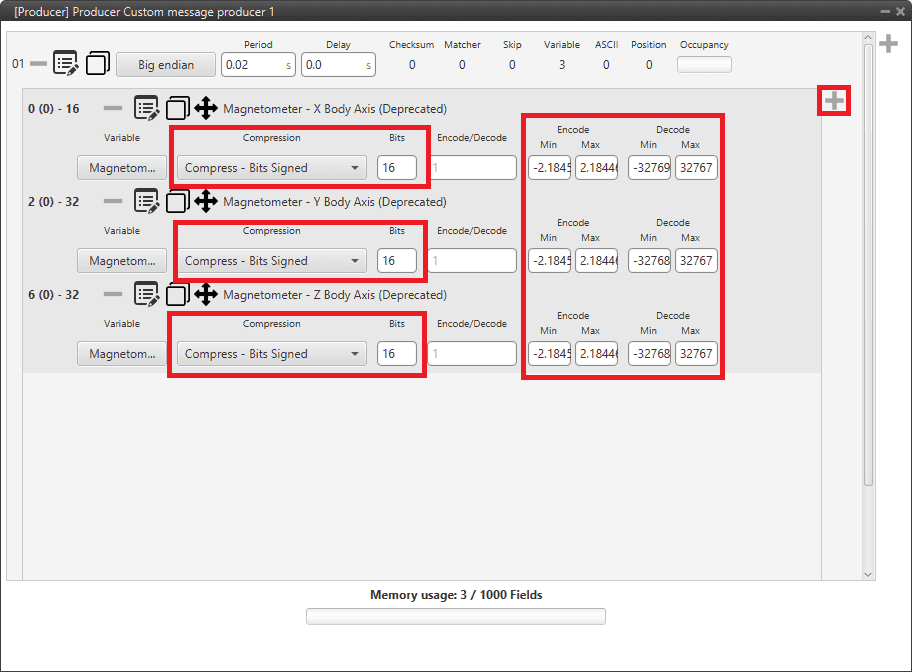
MEX PDI Builder - Custom message Variables configuration
Click on
\(\rightarrow\) Matcher, to add a matcher to the message and configure it as follows:Parameter
Configuration
Value
13
Bits
8
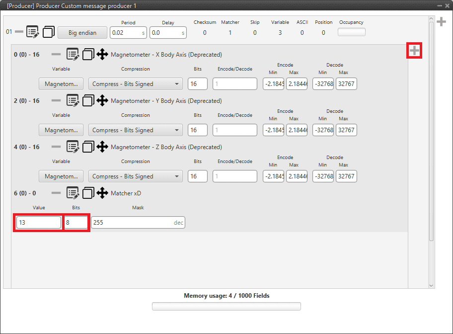
MEX PDI Builder - Custom message Matcher configuration
Matcher explanation
The matcher is a binary code employed to discard messages with errors.
The length and the number represented can be edited clicking on
 of the matcher.
If the receiver does not receive the exact same matcher sequence, the entire message will be discarded, since it will be considered corrupted.
of the matcher.
If the receiver does not receive the exact same matcher sequence, the entire message will be discarded, since it will be considered corrupted.Warning
The order of variables and matcher must be the same.
For more information about custom messages and matchers, read Custom Messages types - Input/Output section of the 1x PDI Builder user manual.
Go to Input/Output menu \(\rightarrow\) Serial panel.
Configure the SCI A, B or C tab accordingly to the consumer selected in step 1 (RS232-A, RS232-B or RS485-C). The configuration is the following:
Note
In this example, RS232-A was selected, so SCI A is configured.
Parameter
Configuration
Baudrate
115200
Length
8
Stop
1
Parity
Disabled
Use address mode
Disabled
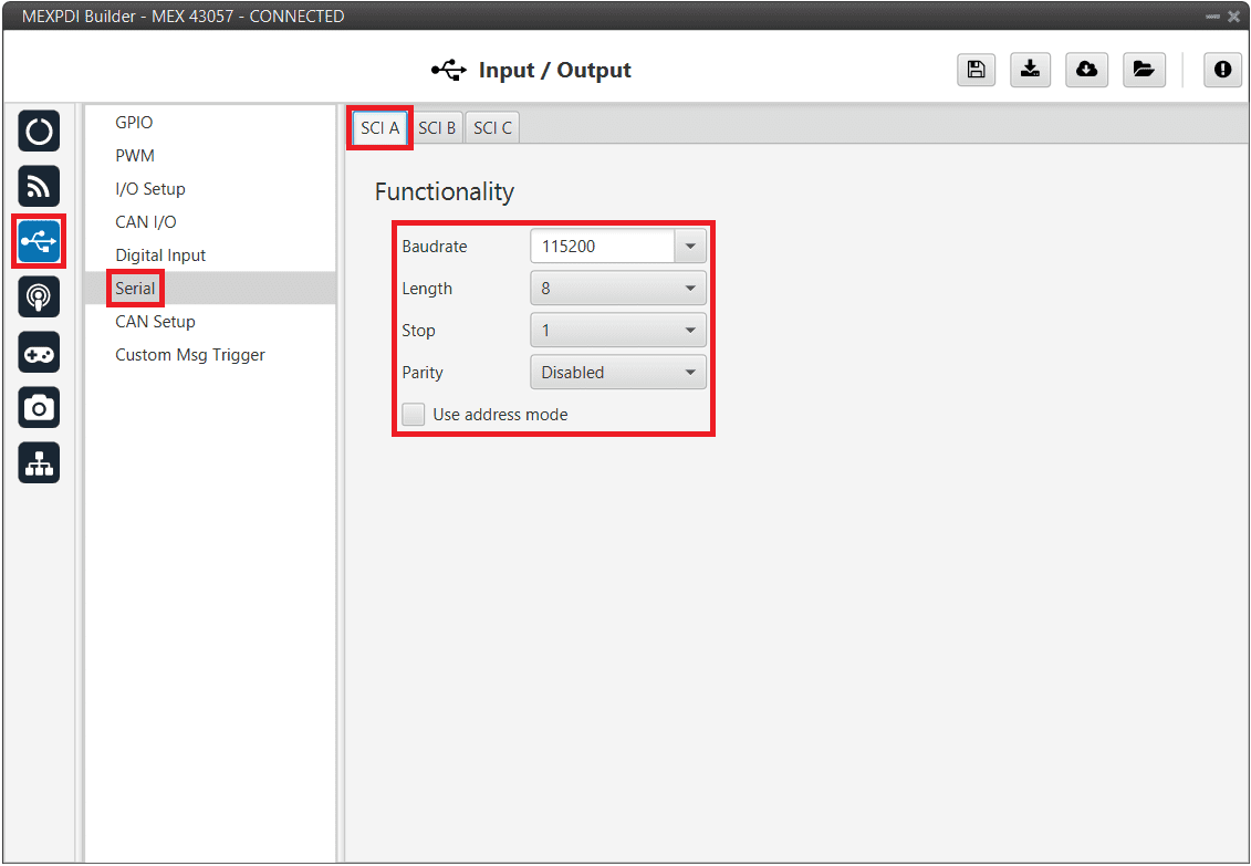
MEX PDI Builder - Serial configuration
Once finished the configuration, click on
 to write the configuration in MEX.
1x PDI Builder side
The configuration for the Autopilot 1x is explained in MEX as Magnetometer Honeywell HMR2300 - Integration examples section of the 1x PDI Builder user manual.
CAN
MEX PDI Builder side
Go to Input/Output menu \(\rightarrow\) I/O Setup panel.
Connect the Custom message producer 1 or 2 to the Serial to CAN 1, Serial to CAN 2 or Serial to CAN 3 port.
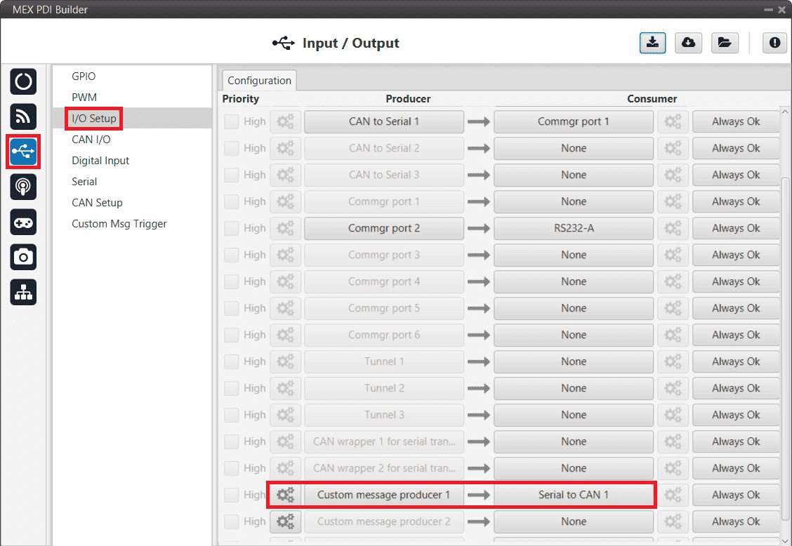
MEX PDI Builder - I/O Setup configuration
Click on the
button of the chosen Custom message producer and add a new message (clicking on ), then configure it as Big endian and set a Period of 0.02 s.
MEX PDI Builder - Custom message configuration
Click on
to add the 3 following Real variables: 313, 314 and 315. Then configure them according to the following table:Parameter
Configuration
Compression
Compress - Bits Signed
Bits
16
Encode
Min: -2.1845334E-4 / Max: 2.1844667E-4
Decode
Min: -32768 / Max: 32767
MEX PDI Builder - Custom message Variables configuration
Click on
\(\rightarrow\) Matcher, to add a matcher to the message and configure it as follows:Parameter
Configuration
Value
13
Bits
8
MEX PDI Builder - Custom message Matcher configuration
Warning
The order of variables and matcher must be the same as shown above.
Go to Input/Output menu \(\rightarrow\) CAN I/O panel \(\rightarrow\) Configuration tab.
Connect the Serial to CAN 1, 2 or 3 to a CAN Output Filter.
Note
The Serial to CAN index must match the one previously selected in the I/O Setup panel (step 1).
MEX PDI Builder - CAN I/O configuration
Select the CAN port by clicking on the
button of the chosen CAN Output Filter.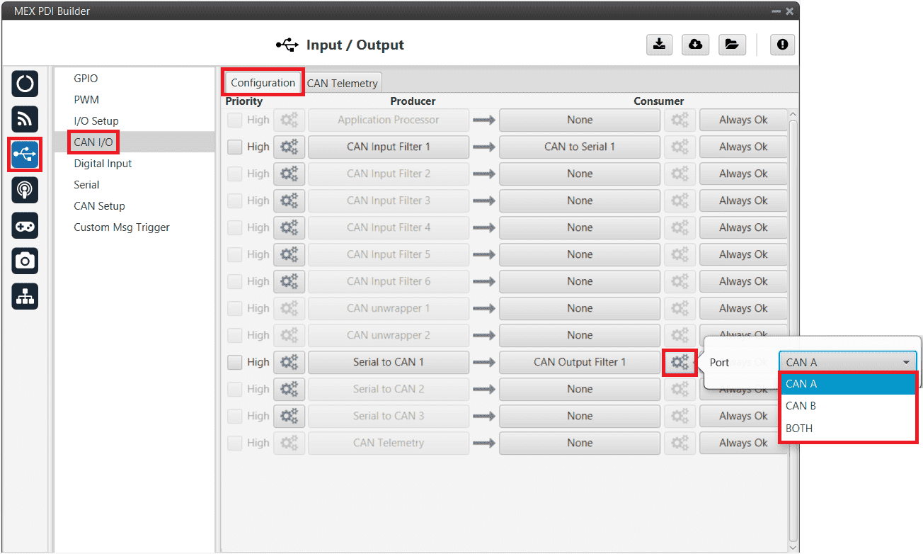
MEX PDI Builder - CAN Output Filter configuration
Asign a CAN ID to the Serial to CAN 1.
Note
This ID must match the one configured for reception in Autopilot 1x with the 1x PDI Builder software.
MEX PDI Builder - Serial to CAN configuration
1x PDI Builder side
The configuration for the Autopilot 1x is explained in MEX as Magnetometer Honeywell HMR2300 - Integration examples section of the 1x PDI Builder user manual.
Reading/Sending RPMs
This section explains the steps to read RPMs.
MEX PDI Builder side
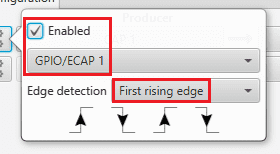
Go to Input/Output menu \(\rightarrow\) GPIO panel.
RPM can be read on the available digital inputs GPIO/ECAP 1 and 2. The chosen pin needs to be configured as “GPIO as input”. In the example shown here, GPIO/ECAP 1 is chosen.
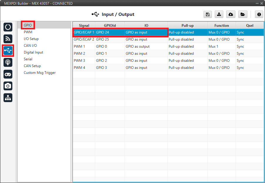
MEX PDI Builder - GPIO configuration
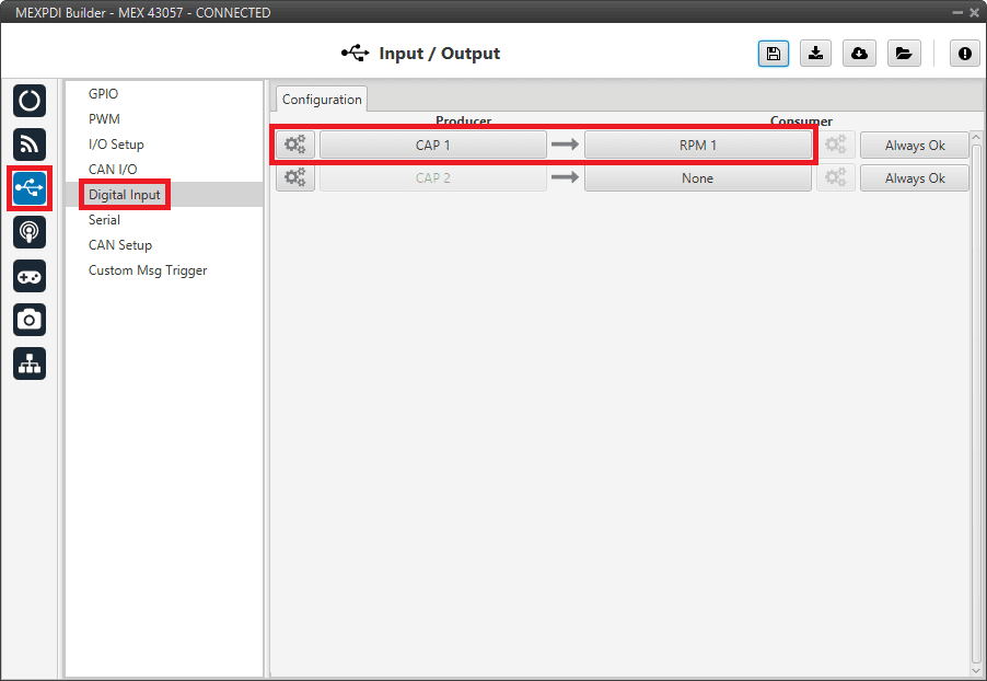
Go to Input/Output menu \(\rightarrow\) Digital Input panel.
There are 2 possible producers: CAP 1 and 2. One needs to be chosen and linked to one of the RPMs consumers (RPM 1-4). For more information about Digital input configuration, read the Digital Input - Input/Output section of this manual.
Then, select an edge detection option: “First rising edge” or “First falling edge”.
MEX PDI Builder - Digital Input configuration
MEX PDI Builder - Edge detection configuration
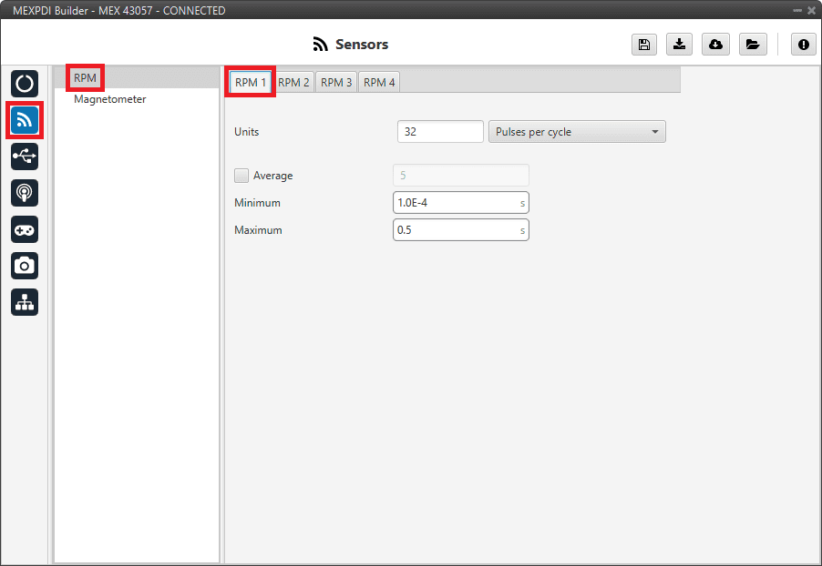
Go to Sensors menu \(\rightarrow\) RPM panel \(\rightarrow\) RPM 1 tab (since RPM 1 has been selected in the Digital Input panel).
Here the expected pulse needs to be defined. For more information on RPM configuration, see RPM - Sensors section of this manual.
MEX PDI Builder - RPM configuration
Go to Input/Output menu \(\rightarrow\) CAN I/O panel \(\rightarrow\) Configuration tab.
Connect CAN Telemetry to a CAN Output Filter as follows (in this example, the RPM1 variable is sent over CAN B bus of the MEX):
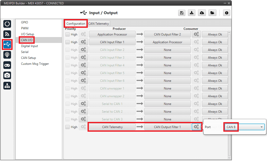
MEX PDI Builder - CAN I/O configuration
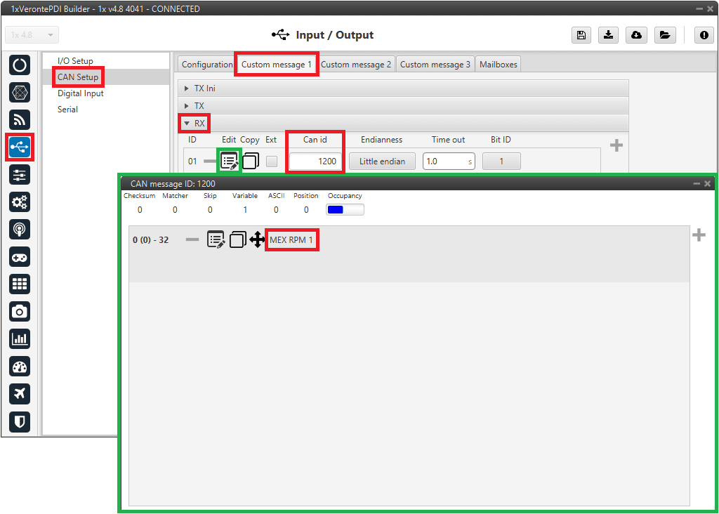
Go to Input/Output menu \(\rightarrow\) CAN I/O panel \(\rightarrow\) CAN Telemetry tab.
A new telemetry message needs to be created with its correspondent ID, endianness and period.
Can ID: 1200.
Endianness: Little endian.
Period: 0.01 s.
In the telemetry message one of MEX variables needs to be selected. As RPM1 has been chosen as consumer in the Digital Input, the variable required to send is RPM1.
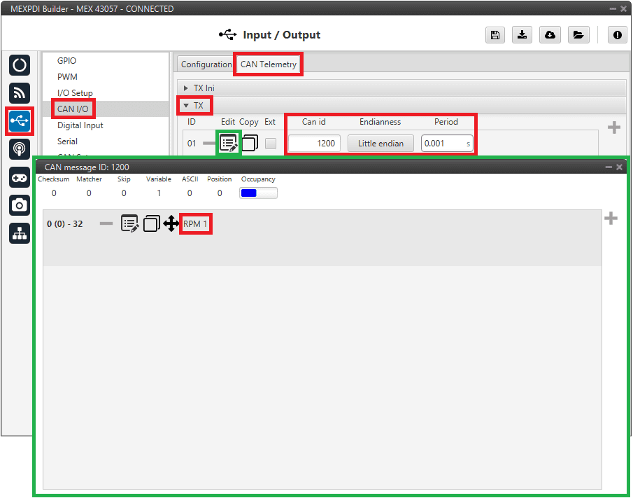
MEX PDI Builder - CAN Telemetry configuration
More information on the configuration of Telemetry messages can be found in the CAN Telemetry - Input/Output section of this manual.
1x PDI Builder side
Go to UI menu \(\rightarrow\) Variables panel \(\rightarrow\) Real Vars tab.
Rename a Real User Variable (32 bits) that will be used to store the value received from MEX:
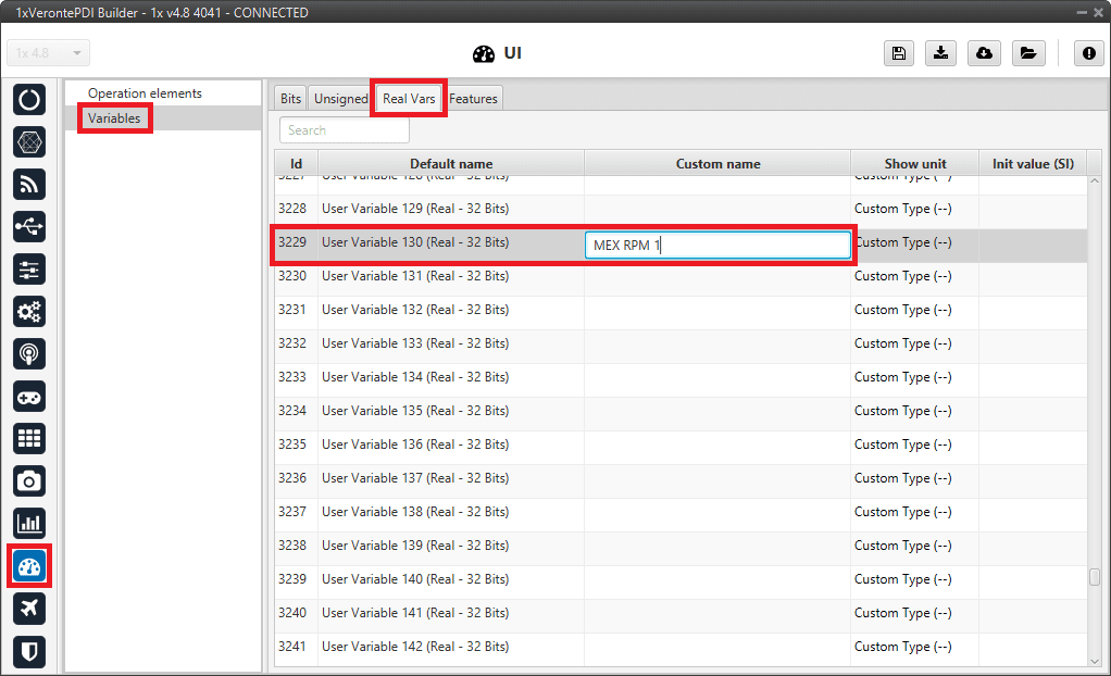
1x PDI Builder - User Variable renamed
Go to Input/Output menu \(\rightarrow\) CAN Setup panel \(\rightarrow\) Mailboxes tab.
Configure, in CAN B, some mailboxes to receive the message with ID 1200:
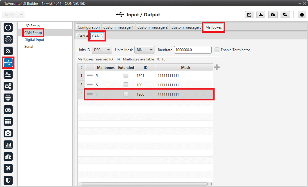
1x PDI Builder - Mailboxes configuration
Go to Input/Output menu \(\rightarrow\) CAN Setup panel \(\rightarrow\) Configuration tab.
Connect an Input filter to a Custom message consumer. Both CAN buses of the Autopilot 1x can be used, as well as normal IDs and extended IDs:
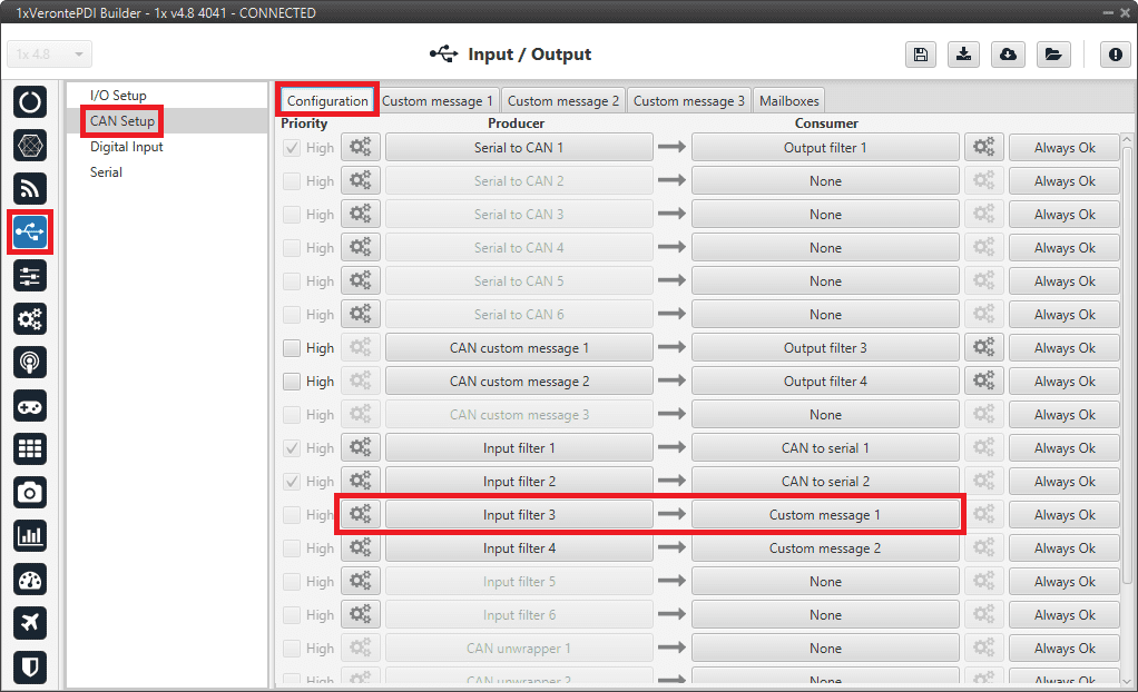
1x PDI Builder - CAN Setup configuration
1x PDI Builder - Input filter configuration
Go to Input/Output menu \(\rightarrow\) CAN Setup panel \(\rightarrow\) Custom message 1 tab (as Custom Message 1 has been selected as consumer).
Configure the message reading and store the received value in the user variable renamed above:
1x PDI Builder - Custom Message configuration
Serial communication
The user can send information through the serial ports of MEX. For this purpose, please read the following steps:
MEX PDI Builder side
I/O Setup configuration
Reception of serial information on RS232-A (producer) is stored in Serial to CAN 2 (consumer).
Transmission of serial information is sent using the CAN to Serial 2 (producer) through RS232-A (consumer).
(‘Serial to CAN’ and ‘CAN to Serial’ are explained in the CAN I/O - Input/Output section of this manual.)
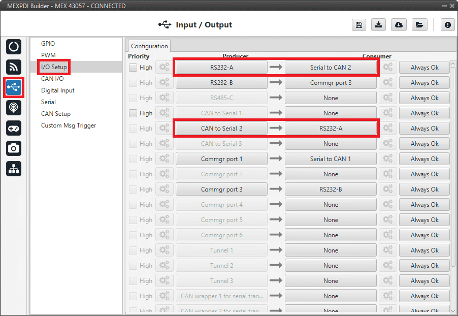
MEX PDI Builder - I/O Setup configuration
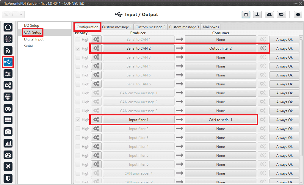
CAN I/O configuration
The information that will be sent over serial port RS232-A is going to be received on the MEX over its CAN B port. A CAN Id of 51 is added to the CAN Input Filter. The incoming information (from Veronte Autopilot 1x) is processed in ‘CAN to Serial 2’.
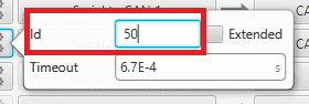
The information coming from port RS232-A and processed as ‘Serial to CAN 2’ is going to be linked to a CAN Output Filter. The information of ‘Serial to CAN 2’ is going to be sent over CAN B with a CAN ID of 50 (to be read by Veronte Autopilot 1x).
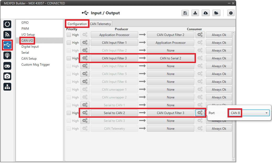
MEX PDI Builder - CAN I/O configuration
MEX PDI Builder - CAN Input Filter configuration
MEX PDI Builder - Serial to CAN configuration
CAN Setup (mailboxes) configuration
Mailboxes need to be defined for the reception of CAN messages. In the example above, mailboxes for ID 51 need to be added on CAN B port.
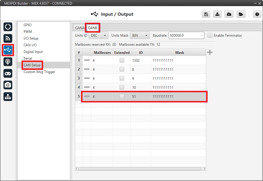
MEX PDI Builder - CAN Setup configuration
1x PDI Builder side
I/O Setup configuration
First, o n the I/O Setup panel link an ‘RS custom message’ to a ‘Serial to CAN’ with the serial data that Autopilot 1x is going to send to MEX.
Then, link a ‘CAN to Serial’ to another ‘RS custom message’ with the expected serial messages that MEX will receive in the selected serial port.
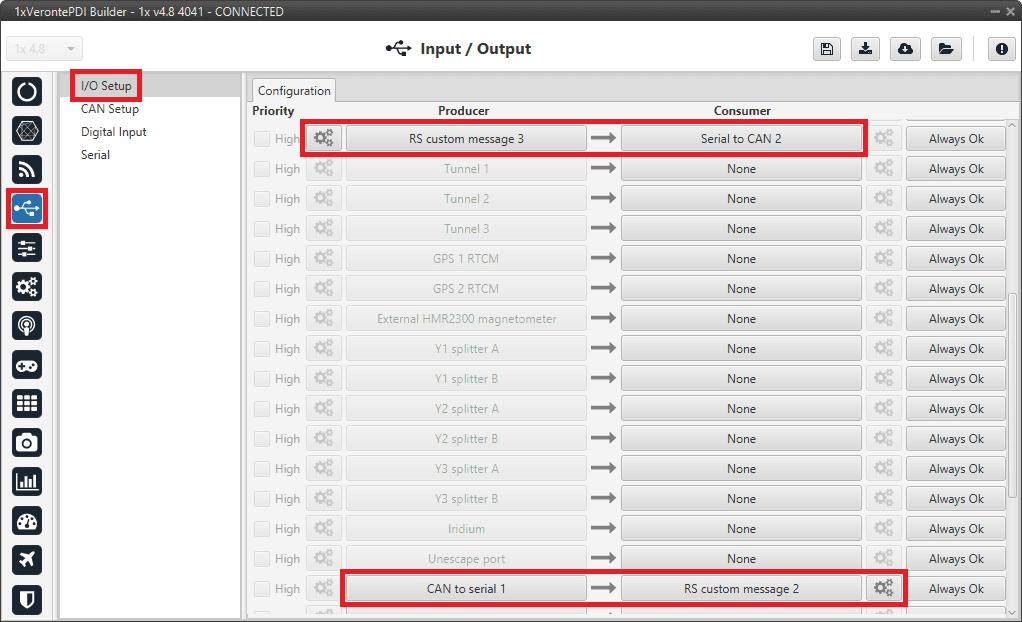
1x PDI Builder - I/O Setup configuration
CAN Setup configuration
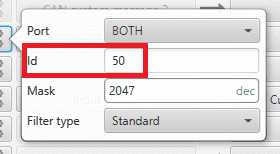
Here, the same IDs employed in MEX for the CAN Input and CAN Output Filters are going to be employed on Veronte Autopilot 1x side, but they must be inverted.
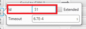
Therefore, the Input filter linked to the chosen ‘CAN to Serial’ needs to have ID 50. And the Output filter linked to the chosen ‘Serial to CAN’ will have ID 51.
1x PDI Builder - CAN Setup configuration
1x PDI Builder - Serial to CAN configuration
1x PDI Builder - Input filter configuration
Mailboxes configuration
Some mailboxes with ID 50 have to be created on whichever chosen reception CAN bus.
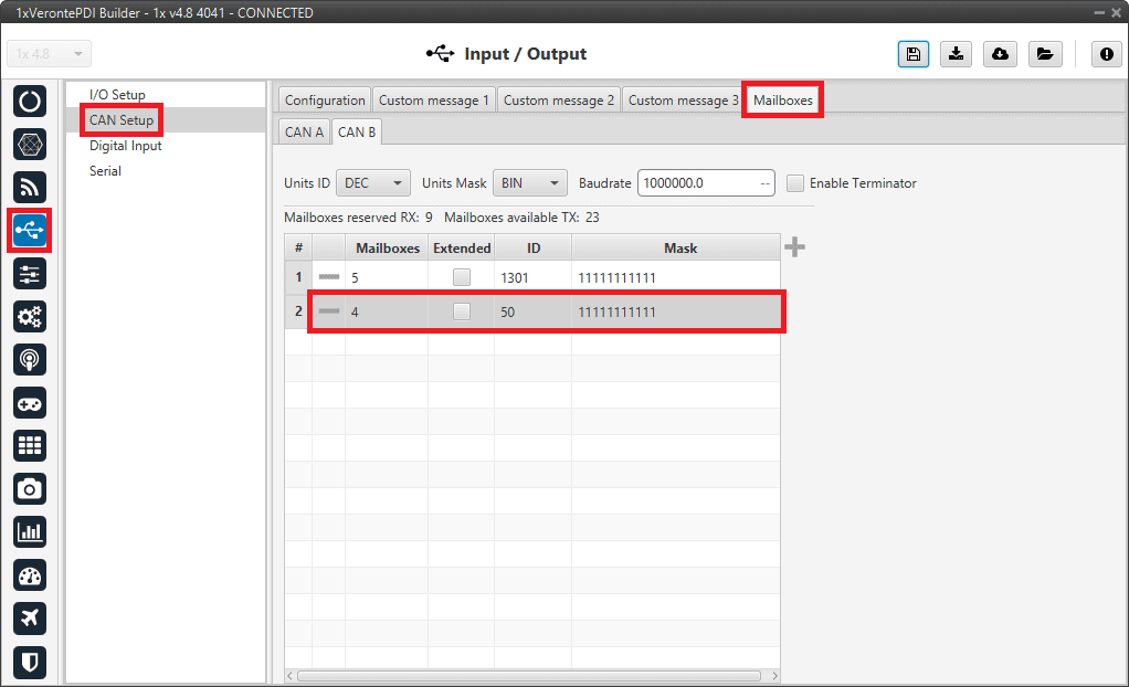
1x PDI Builder - Mailboxes configuration
External devices
The step-by-step instructions for the following external devices are explained in detail in the following sections: