CAN Bus protocol
This section defines the MEX communication protocol.
On the one hand, there are some specific messages that are already configured internally in the system so no configuration in MEX is required for them. Consequently, the device that is intended to communicate with MEX must correctly configure those messages. This message configuration is detailed below in the Application processor section.
On the other hand, it is also detailed the structure of other messages that are not contemplated by default in the MEX configuration but that can be carried out for communication and operation with other devices.
Application processor
This is the configuration of specific messages that must perform any device to communicate with MEX.
Note
No configuration of these messages is required in MEX, as it is already internally configured to process messages configured in this way.
For these messages to be processed correctly, they must be received by the ‘Consumer’ Application processor.
MEX Communication Protocol over CAN bus is defined as follows:

CAN messages structure
cmd (8 bits - 1 byte): first byte refers to the Message Type.
Messages Type are defined as follows:
Type
Value
Description
t_arbitration
0
Arbitration message
t_version
1
Version request / response
t_pwm_0_3_set
2
PWMs 0 to 3
t_pwm_4_7_set
3
PWMs 4 to 7
4
Reserved
t_esc_tm
5
Scorpion Tribunus ESC telemetry data
t_esc_tm2
6
Jeti ESC telemetry data
t_bec_tm1
7
Jeti BEC telemetry data 1
t_bec_tm2
8
Jeti BEC telemetry data 2
t_temp_tm
9
Jeti Temperature sensor telemetry data
t_mcu_cmd
10
MCU battery command
t_pwm_8_11_set
11
PWMs 8 to 11
t_pwm_12_15_set
12
PWMs 12 to 15
t_pwm_16_19_set
13
PWMs 16 to 19
14
Reserved
15
Reserved
t_cmd_maint
16
Command to go to Maintenance Mode
t_stick_sel
17
Command for Stick selection
t_mcu_tm1
18
MCU telemetry data 1
t_mcu_tm2
19
MCU telemetry data 2
Note
All these Message Type are defined as a “Matcher” in the CAN custom messages configuration. For example, for PWMs 0-3, the Message Type will be configured as follows:
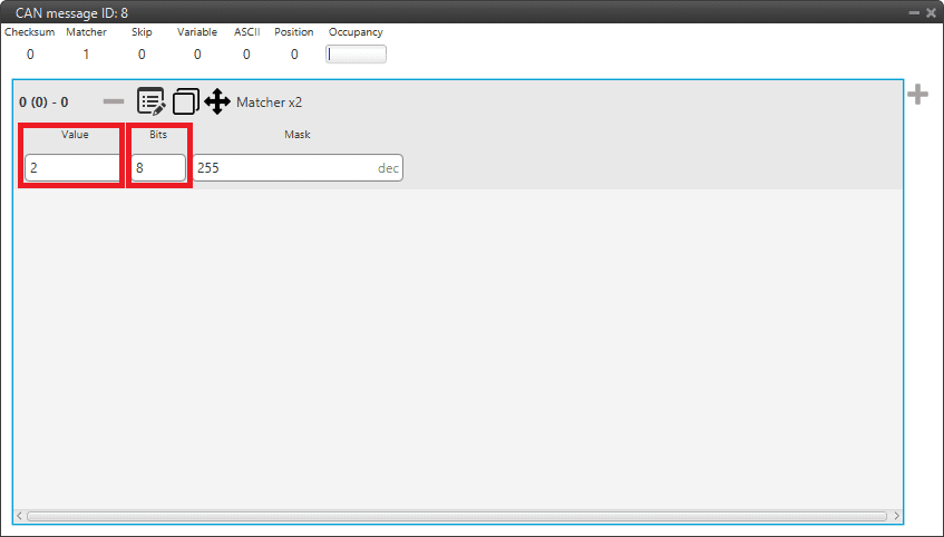
Message Type example
Value: 2, since it is the value for the message for PWMs 0 to 3 (it is indifferent to the PWM number).
Bits: 8, because the Message Type is an 8-bit message.
data (up to 56 bits - 8 bytes): The following bytes refer to the Message data .
Next sections decribe each one of the possible messages with an example. The following examples include complete messages, so each beginning corresponds to Message Type.
MEX Status
MEX status message is composed as follows:
Type |
Value |
Bits |
Description |
|---|---|---|---|
cmd (t_version) |
1 |
8 |
Version request / response |
data |
- |
8 |
Version - Major |
data |
- |
8 |
Version - Minor |
data |
- |
8 |
Version - Revision |
data (sysaddr) |
- |
8 |
Serial number - address 0 |
data (sysaddr) |
- |
8 |
Serial number - address 1 |
data |
- |
1 |
System Error bit (ID 7) |
data (MEX status) |
- |
1 |
System power up bit error bit (ID 12) |
data (MEX status) |
- |
1 |
PDI error bit (ID 9) |
data (MEX status) |
- |
1 |
Memory Allocationbit (ID 8) |
data (MEX status) |
- |
1 |
File system error bit (ID 6) |
data (MEX status) |
- |
1 |
CAN A ERROR bit (ID 73) |
data (MEX status) |
- |
1 |
CAN B ERROR bit (ID 74) |
data (MEX status) |
- |
1 |
false |
data (MEX status) |
- |
1 |
Arbiter enabled |
data (MEX status) |
- |
1 |
Arbiter status |
Arbitration
MEX Arbitration Status message is composed as follows:
Message 1: Sent when “Send status” is enabled
Type
Value
Bits
Description
cmd (t_arbitration)
0
8
Arbitration message
Flag
255 ([0xFF])
8
Status Flag
CAP
-
7
Active Autopilot (Current)
data
-
1
Arbitrating
data
-
1
AP0 Alive
data
-
1
AP1 Alive
data
-
1
AP2 Alive
data
-
1
AP3 Alive (External)
data
-
1
AP0 Ready
data
-
1
AP1 Ready
data
-
1
AP2 Ready
data
-
1
AP3 Ready (External)
data (MEX status)
-
1
System bit error (ID 7)
data (MEX status)
-
1
System power up bit error (ID 12)
data (MEX status)
-
1
PDI bit error (ID 9)
data (MEX status)
-
1
Memory Allocation bit (ID 8)
data (MEX status)
-
1
File system bit error (ID 6)
data (MEX status)
-
1
CAN A bit error (ID 73)
data (MEX status)
-
1
CAN B bit error (ID 74)
data (MEX status)
-
1
false
data (MEX status)
-
1
Arbiter enabled
data (MEX status)
-
1
Arbiter status
Message 2 (One for each Veronte Autopilot 1x): Sent when “Send score” is enabled
Type
Value
Bits
Description
cmd (t_arbitration)
0
8
Arbitration message
data
-
8
Autopilot ID [0, 3]
data
-
32 (4 bytes )
Autopilot score as Float
Command PWMs
Each PWM in MEX has to be associated to a Sub Id that indicates which CAN Bus message’s PWM is listening to.
That allows to control up to four PWMs using the same message if it is desired. Each message is composed by 4 PWMs maximum.
PWMs from 0 to 3 are sent in a message that includes 4 PWMs coded as 12-bit integers:
Type
Value
Bits
Description
cmd (t_pwm_0_3_set)
2
8
PWMs 0 to 3
data (pwm0)
-
12
PWM value for sub-id 0
data (pwm1)
-
12
PWM value for sub-id 1
data (pwm2)
-
12
PWM value for sub-id 2
data (pwm3)
-
12
PWM value for sub-id 3
PWMs from 4 to 7 are sent in a message that includes 4 PWMs coded as 12-bit integers:
Type
Value
Bits
Description
cmd (t_pwm_4_7_set)
3
8
PWMs 4 to 7
data (pwm0)
-
12
PWM value for sub-id 4
data (pwm1)
-
12
PWM value for sub-id 5
data (pwm2)
-
12
PWM value for sub-id 6
data (pwm3)
-
12
PWM value for sub-id 7
PWMs from 8 to 11 are sent in a message that includes 4 PWMs coded as 12-bit integers:
Type
Value
Bits
Description
cmd (t_pwm_8_11_set)
11
8
PWMs 8 to 11
data (pwm0)
-
12
PWM value for sub-id 8
data (pwm1)
-
12
PWM value for sub-id 9
data (pwm2)
-
12
PWM value for sub-id 10
data (pwm3)
-
12
PWM value for sub-id 11
PWMs from 12 to 15 are sent in a message that includes 4 PWMs coded as 12-bit integers:
Type
Value
Bits
Description
cmd (t_pwm_12_15_set)
12
8
PWMs 12 to 15
data (pwm0)
-
12
PWM value for sub-id 12
data (pwm1)
-
12
PWM value for sub-id 13
data (pwm2)
-
12
PWM value for sub-id 14
data (pwm3)
-
12
PWM value for sub-id 15
PWMs from 16 to 19 are sent in a message that includes 4 PWMs coded as 12-bit integers:
Type
Value
Bits
Description
cmd (t_pwm_16_19_set)
13
8
PWMs 16 to 19
data (pwm0)
-
12
PWM value for sub-id 16
data (pwm1)
-
12
PWM value for sub-id 17
data (pwm2)
-
12
PWM value for sub-id 18
data (pwm3)
-
12
PWM value for sub-id 19
A complete example of how to command PWMs from Veronte Autopilot 1x and read them into MEX can be consulted in the Commanding/Reading PWMs - Integration examples section of the MEX PDI Builder user manual.
MCU telemetry
From MEX
The telemetry sent by MEX through CAN Bus is composed by:
Message 1:
Type
Value
Bits
Description
cmd (t_mcu_tm1)
18
8
MCU telemetry data 1
data
-
8
Battery Serial Number [0]
data
-
8
Battery Serial Number [1]
data
-
8
Battery Temperature (as received from MCU)
data
-
8
Low Cell Voltage (as received from MCU)
-
4
Reserved (Zeros)
data (Status Bit)
-
1
PWM receiving Ok
data (Status Bit)
-
1
CAN PWM receiving Ok
data (Status Bit)
-
1
CAN B receiving
data (Status Bit)
-
1
CAN A receiving
Message 2:
Type
Value
Bytes
Description
cmd (t_mcu_tm2)
19
1
MCU telemetry data 2
data
-
1
Battery Serial Number [2]
data
-
1
Battery Serial Number [3]
data
-
1
Battery Serial Number [4]
data
-
1
Battery Serial Number [5]
data
-
1
Battery Serial Number [6]
data
-
1
Battery Serial Number [7]
To MEX
The telemetry sent to MEX must be configured as follows:
Type |
Value |
Bytes |
Description |
|---|---|---|---|
cmd (t_mcu_cmd) |
10 |
1 |
MCU battery command |
data |
- |
1 |
SUB-id A |
data |
- |
1 |
LED Value A |
data |
- |
1 |
SUB-id B |
data |
- |
1 |
LED Value B |
data |
- |
1 |
SUB-id C |
data |
- |
1 |
LED Value C |
Each MEX will use the SUB-id of the PWM associated to the “Scorpion Tribunus”/PWM ID to identify the value to be used.
Scorpion Tribunus ESC Telemetry
The telemetry read from the Scorpion ESC is sent as:
Type |
Value |
Bytes |
Description |
|---|---|---|---|
cmd (t_esc_tm) |
5 |
1 |
Scorpion Tribunus ESC telemetry data |
data |
- |
1 |
Input voltage in range [0, 85] |
data |
- |
1 |
Temperature in Celsius |
data |
- |
1 |
Error Flags from the ESC |
data |
- |
1 |
Current in Amps [0, 255] |
data |
- |
1 |
Consumption in mAmps [0, 25500] |
data |
- |
1 |
RPMs [0, 25500] |
data |
- |
1 |
Throttle as percentage*2 [0, 200] |
JetiTM ESC Telemetry
The telemetry read from Jeti-TM compatible ESCs is sent as:
Type |
Value |
Bytes |
Description |
|---|---|---|---|
cmd (t_esc_tm2) |
6 |
1 |
Jeti ESC telemetry data |
data |
- |
1 |
Throttle value [0, 200] |
data |
- |
2 |
Current RPMs |
data |
- |
10 bits |
Input voltage in the range [0, 70] Volts |
data |
- |
10 bits |
Temperature in the range [0, 575] Kelvin |
data |
- |
12 bits |
Current in the range [0, 400.0] Amps |
Jeti BEC Telemetry
The telemetry read from Jeti BEC will be sent in 2 different messages:
Message 1:
Type
Value
Bits
Description
cmd (t_bec_tm1)
7
8
Jeti BEC telemetry data 1
data
-
16
Device ID
data
-
12
Input voltage in the range [0, 70] Volts
data
-
12
Output voltage in the range [0, 70] Volts
data
-
12
Temperature in the range [0, 575] Kelvin
Message 2:
Type
Value
Bits
Description
cmd (t_bec_tm2)
8
8
Jeti BEC telemetry data 2
data
-
16
Device ID
data
-
12
Current in range [0, 100.0] Amps
Jeti Temperature Sensor Telemetry
The telemetry read from a Jeti Temperature sensor will be sent as:
Type |
Value |
Bits |
Description |
|---|---|---|---|
cmd (t_temp_tm) |
9 |
8 |
Jeti Temperature sensor telemetry data |
data |
- |
16 |
Device ID |
data |
- |
12 |
Measured temperature 1 in the range [0, 750] Kelvin |
data |
- |
12 |
Measured temperature 2 in the range [0, 750] Kelvin |
Set Maintenance Mode Command
This command will configure the MEX in maintenance mode, setting its configuration in a way that communications can work over SCI-A, SCI-B or Serial-to-CAN configured as:
SCI-A and SCI-B: 115200 bauds, 8 data bits, 1 stop, no parity.
Serial to CAN:
TX Id: 1301
RX Id: 1301
The format of the command is:
Type |
Value |
Bytes |
Description |
|---|---|---|---|
cmd (t_cmd_maint) |
16 |
1 |
Command to go to Maintenance Mode |
Stick Selection Command
This command is used to enable or disable the MEX PPM reader. If address received matches the MEX’s one, MEX PPM reader will be enabled, otherwise it will be disabled.
The format of the command is:
Type |
Value |
Bytes |
Description |
|---|---|---|---|
cmd (t_stick_sel) |
17 |
1 |
Jeti Temperature sensor telemetry data |
data (sysaddr) |
- |
1 |
address 0 |
data (sysaddr) |
- |
1 |
address 1 |
MEX as external magnetometer Honeywell HMR2300
In this section it is explained how to configure the MEX magnetometer to be used as an external magnetometer for another device, either via CAN or serial.
CAN
The CAN messages sent by MEX must have the following structure:
CAN Id: It can be in standard frame format (11-bits) or in extended frame format (29-bits). The CAN Id frame format will depend on the CAN protocol supported by the receiving device.
Variables: The MEX variables associated with the magnetic data are:
ID 313: Magnetometer - X Body Axis
ID 314: Magnetometer - Y Body Axis
ID 315: Magnetometer - Z Body Axis
In addition, users must configure the sending period and endianness of these messages, as well as the baudrate of the CAN bus.
Note
Detailed information on how to build CAN messages can be consulted in the Custom Messages types - Input/Output section of the 1x PDI Builder user manual.
The device receiving this information, must be configured properly so that it matches what has been configured in MEX.
Serial
The serial messages sent by MEX must have the following structure:
Variables: The MEX variables associated with the magnetic data are:
ID 313: Magnetometer - X Body Axis
ID 314: Magnetometer - Y Body Axis
ID 315: Magnetometer - Z Body Axis
Checksum: It is useful to include a checksum to verify that the message is sent and received correctly.
In addition, users must configure the sending period of these messages, as well as the baudrate of the serial port (RS232/RS485).
Note
Detailed information on how to build CAN messages can be consulted in the Custom Messages types - Input/Output section of the 1x PDI Builder user manual.
The device receiving this information, must be configured properly so that it matches what has been configured in MEX.
Communication with MEX
MEX can also be used to receive data through a communication protocol and transmit it through another.
Serial reception and CAN transmission
For serial reception, follow the steps below:
Set the baudrate of the serial port used, RS232 or RS485.
In order to communicate with the device sending the data, serial messages must be built to match the serial protocol specified by that device.
Note
Normally, it contains the variables to be stored in MEX and a checksum to verify that the message is sent and received correctly. Please refer to the list of variables in this manual to see the variables available in MEX.
Configure the timeout of the messages. Remember that it has to be higher than the message sending period specified in the sending device.
Set the time to idle for these messages.

For CAN transmission, follow the steps below:
Build a CAN message with the following structure:
CAN Id: It can be in standard frame format (11-bits) or in extended frame format (29-bits). The CAN Id frame format will depend on the CAN protocol supported by the receiving device.
Variables: The variables in which the information received via serial has been stored must be set.
Please refer to the list of variables in this manual to see the variables available in MEX.
Configure the sending period and endianness of these messages, as well as the baudrate of the CAN bus.
The device receiving this information, must be configured properly so that it matches what has been configured in MEX.
CAN reception and serial transmission
For CAN reception, follow the steps below:
In order to communicate with the device sending the data, the CAN messages must be built to match the CAN protocol specified by that device.
Note
Normally, it is composed of a CAN Id and variables to be stored in MEX. Please refer to the list of variables in this manual to see the variables available in MEX.
Configure the sending period and endianness of these messages, as well as the baudrate of the CAN bus.
For serial transmission, follow the steps below:
Build a serial message with the variables received via CAN:
Variables: The variables in which the information received via CAN has been stored must be set.
Please refer to the list of variables in this manual to see the variables available in MEX.
Checksum: It is useful to include a checksum to verify that the message is sent and received correctly.
Configure the sending period of these messages, as well as the baudrate of the serial port (RS232/RS485).
The device receiving this information, must be configured properly so that it matches what has been configured in MEX.