Gyroscope
The gyroscope from the IMU can be configured as explained in the menus shown below.
The user can choose between 3 types of source for the gyroscope.
Integer var sensor 1-2. Veronte uses a integer value provided by an external sensor.
Decimal var sensor 1-2. Veronte uses a decimal value provided by an external sensor.
Internal 1-2. Veronte uses the internal sensor.
Integer var sensor
In this menu it is possible to configure integer variables provided by an external sensor.
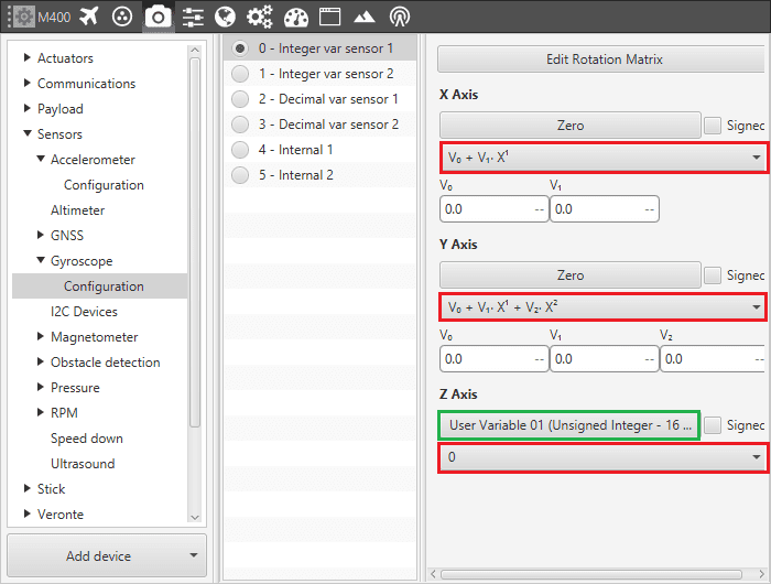
Integer var Gyroscope Menu - Configuration Parameters
When Integer var sensor 1 or 2 are selected, the previous panel will be shown. In this panel, the user selects the variable that has been stored in a user variable (Green Box) and the operations that will be carried on (Red Box). It is possible to use the signal through a linear or quadratic relation. The following image shows an example of a linear relation.
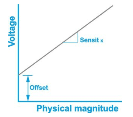
Linear relation of 2 Variables
The process of configuration has to be done using Custom Messages. This is to be configured in Devices - Others - Digital - I/O Manager. The configuration will depends on the device in use and its communication protocol.
Decimal var sensor
In this menu, the user selects real variables for each axis (X,Y,Z), these do not requiere a signal treatment. The process of configuration is similar to the one carried out when configuring a Integer Variable.
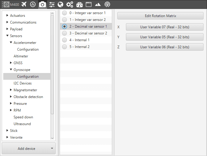
Decimal var Gyroscope Menu - Configuration Parameters
Internal
This last menu available displays the posible parameters that can be configured for the internal Gyroscope.
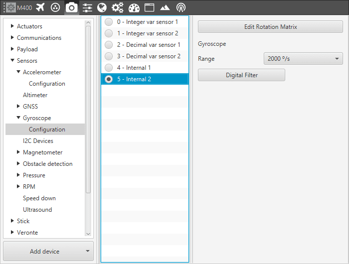
Gyroscope Menu - Configuration Parameters
Warning
Edit Rotation Matrix brings the position of the gyroscope inside the Veronte Autopilot, it must NOT be changed under any circumstance.
In this menu it is possible to set different options regarding range and filters from the gyroscope. The parameters that can be modified are:
Range. Sets the maximum range of performance, high ranges implies less precision while small ranges might mean the system saturates. Values allowed are 125°/s, 250°/s, 500°/s, 1000°/s and 2000°/s.
Digital filter. Enables a low pass filter which its cutoff frequency is configured manually, allowing the user to input any desired value in Hz. It is a software filter.