Physical
Calibration Interface
The menu available on Devices -> Actuators -> Physical allows the calibration of all connected actuators. On this panel it is possible to set actuator position for each control signal/output, allowing to configure the maximum and minimum values and its custom performance. On the Figure below the configuration of a tailless aircraft , i.e. flying wing , is used as an example.
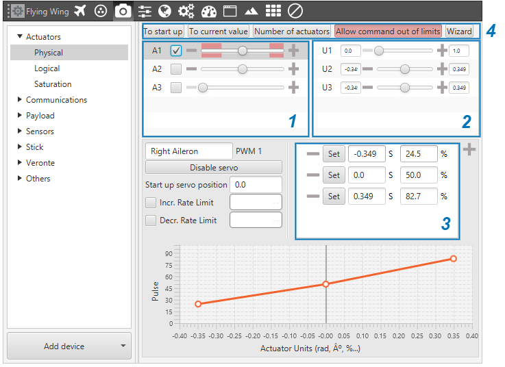
Physical Actuators Menu
The parameters of each one of the servos can be configured in two different ways: directly on the menu shown in the previous Figure, or through the wizard button. This last option is the recommended upon first configuration, leaving the other option for adjustments and advanced settings.
The options of the calibration menu are presented next:
Servos (actuators): this menu contains the servos of the platform. Moving the scrolling bar will change the servo position, but the signal to the system will only be sent if the checkbox next to the servo number (A1, A2…) is marked. The manual movement of the servos can only be done in the “Initial” phase (when there is no phase selected in Veronte Panel).
Control signals: this menu contains the variables that represent the control signals/outputs \(U\) generated by the system. Considering the flying wing, the controls are thrusting (U1), pitching (U2) and rolling (U3), so there are 3 different controls in total. The mapping from the controls to the servo positions is indicated within the SU matrix, which is set in Devices - Actuators - Logical. When moving the scrolling bar of one of the control channels, the corresponding movement on the servos will also be represented.
Servo position – PWM: this option is used to set the mapping from servo position \(S\) to PWM signal. For example, a 20º degrees deflection (0.349 rad) of the right elevon corresponds to an 82’7 % pulse to be sent to the corresponding servo. The mapping is expressed through the graph, where the user can introduce as many points as desired.
The other tools that appear on the menu are:
To start up: set initial values of the actuators.
To current value: set actuators to the current value – requires the physical platform to be connected.
Change size actuators: change the total number of available actuators.
Allow command out of limits: allow out-of-limits motion for the selected actuator.
Wizard: explained below.
Disable/Enable servos: allows the user to enable or disable a configured actuator.
Start up servo position: sets the pulse value for the start up configuration.
Increasing/Decreasing Rate limit: sets a rate limit for increasing/decreasing motions of the servo.
The procedure to follow when configuring a servo/actuator is:
Firstly, set the scrolling bar to its middle position.
Secondly, click on Enable: this avoids the problem of enabling a servo when it is in an extreme position, which can produce a malfunction.
Set the desired maximum \(S_{max}\) and minimum \(S_{min}\) values of the actuator \(S\) (a restrictive approximate value works).
Note
\(S_{max}\) and \(S_{min}\) can be chosen to match the actual physical value they represent, e.g. the angle of delfection of an aileron. But they can also be chosen not to match a physical variable, and it won’t affect the autopilots behaviour as these \(S\) values are the representation of PWM signals. And the latter are the ones that correspond to an actual control surface/device movement.
Take a motor, for instance. The minimum PWM signal corresponds to a 0 rpm state, but a maximum PWM signal corresponds to finite number of rpms. In this case it’s easier to assume \(S_{max}=1\) and \(S_{min}=0\). The same could be done for the ailerons. If they are deflected the same amount in both directions then \(S_{max}=1\) and \(S_{min}=-1\).
Finally, connect the physical actuator and adjust its minimum and maximum values.
Configuration Wizard
Configuration wizard is recommended on first system configuration. It guides the user for configuring actuator limits and performance. This calibration should be performed in order to define the relationship between the autopilot output and real servo position.
In order to set servo positions, it is possible to enable servo movement from the user interface. Check the box on the left of each servo in order to enable servo movement, once enabled, servos will move according to the bar. On the bottom left part of the windows, there is the Stop PWM, with which all checkboxes are disabled.
If the user wants to finish the wizard and keep the results configured up to that point, just click on Finish on the bottom right part.
Limits: Set maximum and minimum pulse value for the mechanical limits on the actuator.
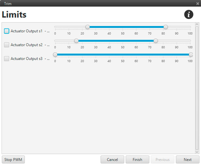
Trim Wizard – Limits
The autopilot will never command the actuator outside these limits, preventing mechanical damages in the aircraft.
Neutral: Set neutral position for actuators and control channels. This position is set as a reference in the system and will remain as the default position on system startup. On the right, there is the column for U, where the neutral value for that particular control output is chosen.
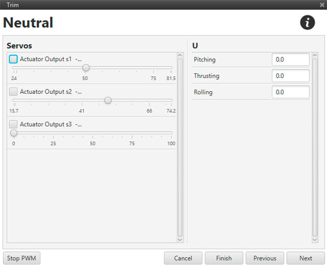
Trim Wizard – Trim Wizard – Neutral
Select: Select a servo to trim. The servos are sorted depending on which is affected by each control input.
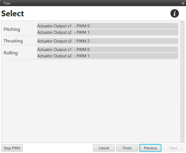
Trim Wizard – Trim Wizard – Select Output
Once a servo is trimmed for a defined control channel, it will not be displayed for trim in other control channels.
Value: Enter the maximum and minimum actuator position for the control variable. These values correspond to the components of S, for example, a maximum deflection of 20 degrees will correspond to a 75 % pulse and a minimum of -20 a 25%. These limits don’t have to be the same as the mechanical limits of the actuator establish in the first screen of the wizard.
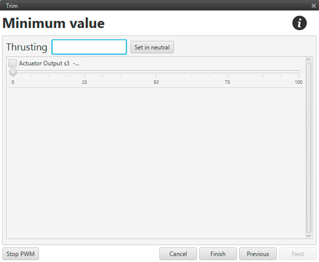
Trim Wizard – Trim Wizard – Min/Max Values
When the process is finished, a summary display appears, showing the user the graphs relating all the information provided, as the on the bottom part of the main display.