Logical
\(\boldsymbol{SU}\) & \(\boldsymbol{US}\) Matrices
\(SU\) and \(US\) are two matrices (inverse of one another, respectively) which contain the relationship between actuator outputs \(S\) and control outputs \(U\), i.e. the influence of each control channel on each actuator output. The option of having a configurable \(SU\) matrix allows Veronte autopilots to control any type of vehicle, independently of how its control surfaces/devices are set and adjusted.
\(U\) is a vector which contains the control outputs of the platform, e.g. pitch, roll, yaw, throttle, etc. The values of \(U\) do not represent a physical variable. They are instead fictitious variables which are used in the control algorithm. What is actually applied to the system are the actuators movements, i.e. the PWM signals sent to the servos, which are mapped in the \(S\) vector – see Devices - Actuators - Physical for more information. The relation between \(S\) and \(U\) is essential for the right attitude control of the platform.
In order to define \(SU\), the user needs to go to Devices -> Actuators -> Logical and click on Edit – see Figure below. A pop-up window will open containing the matrix. Control outputs \(U\) are placed on the columns and actutator outputs \(S\) on the rows. Clicking on the ‘+’ sign allows the user to add a new \(U\) or \(S\), adding a new column or row will appear, respectively.
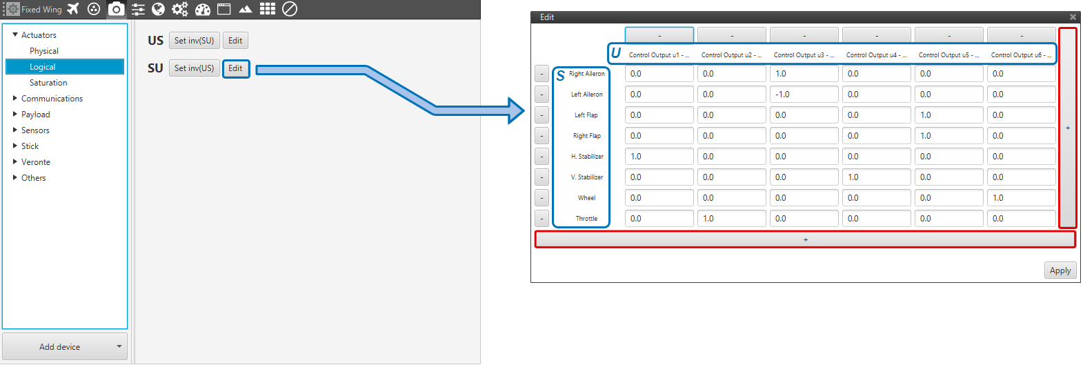
\(SU\) Matrix Menu
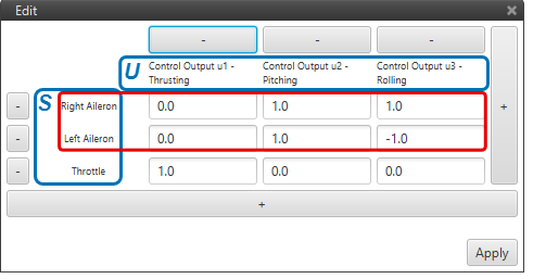
Definition of \(US\) is also avaialble, but it is recommended to go with the first as it is more intuitive to define. Let’s comsider the \(SU\) of a fixed-wing aircraft – see the Figure below. On the \(S\) vector there are 8 entries, i.e. 8 actuators; and on the \(U\) vector there are 6 control outputs.
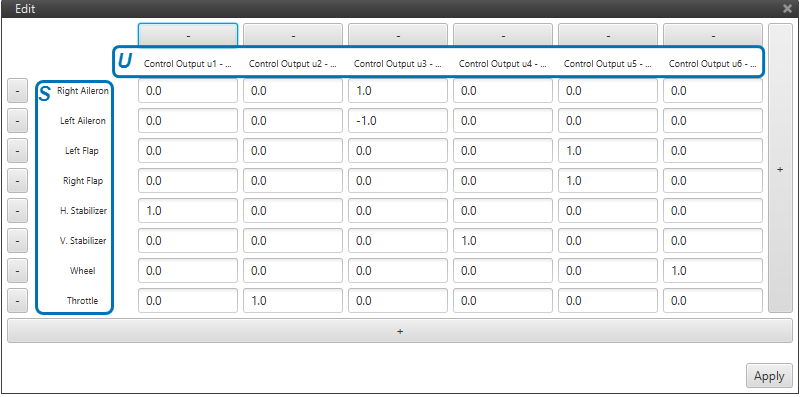
\(\boldsymbol{SU}\) Matrix for a Fixed-Wing aircraft
As we see in the Figure above, the user defines which actuators influence which control channels. For instance, only the actuator throttle, e.g the engine – influences the control output \(U_{2}\): thrusting; and only the horizontal stabilizer influences \(U_{1}\): pitching.
Warning
Regarding the selection of the parameters of \(SU\) matrix:
The order of magnitude of the parameters should be respected at least for every row, i.e. every control channel, as long as there are no coupled control channels \(U\).
Note
Good practice recommendations:
Unitary values are recommended. Doing so, \(U\) will be equal to \(S\). And if \(S\) has been defined according to a physical value – e.g. deflected angle, then control outputs can be easier to understand.
The order of magnitude and the value of the \(SU\) parameters will not influence control algorithm calculations. But it will affect the control parameters, i.e. the control gains.
It is recommended to keep the same order of magnitude for the whole matrix. That will allow an easier set up of a scaled version of the platform. Keeping the same \(SU\) and knowing the scaling factor, then the new control gains should be the old ones multiplied by that scaling factor. This practice can also be useful for transition to similar platforms.
The \(SU\) vector should be defined accordingly in order to follow the sign convention for aerial navigation: a positive roll lowers the right wing, a positive pitch moves the nose up and a positive yaw moves the nose the right.
Important
Regarding \(SU\) parameters of opposite sign:
In the above Figure one can see that for control output \(U_{3}\) : rolling, the right aileron indicates 1 and the left aileron -1. In other words, one moves opposite to the other. But this is a mere convention. Everything depends on the ailerons PWM to servo movement curves – defined in Devices -> Actuators -> Physical.
Coming back to the matrix \(SU\) menu, the user should click on Apply once it has finished. A pop-up window will appear (see Figure below) warning the user about the \(US\) matrix needing to be updated: it can be automatically updated from the \(SU\), or introduced manually. It is advised to go with the first option.
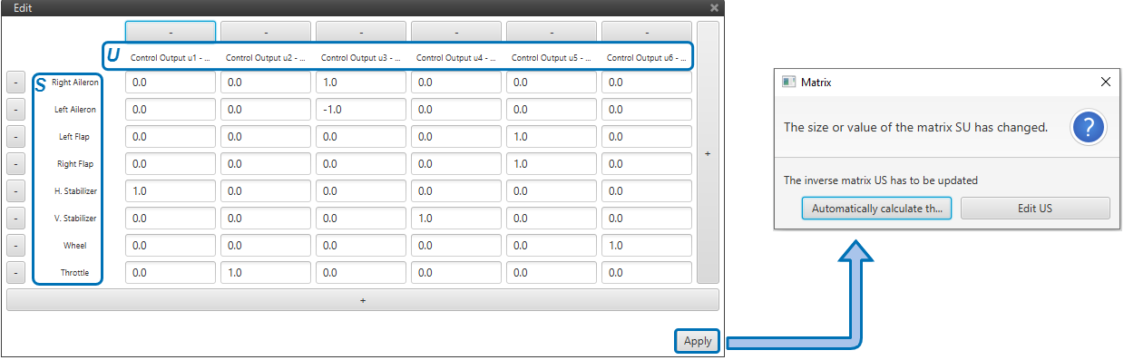
\(\boldsymbol{SU}\) to \(\boldsymbol{US}\)
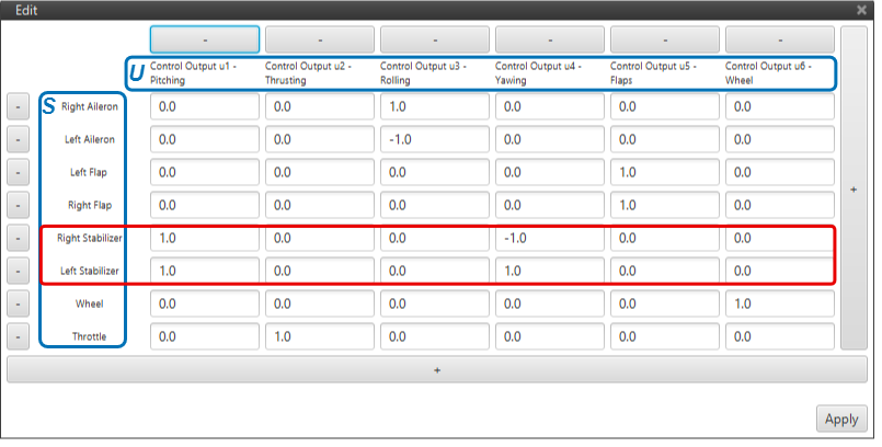
The \(US\) matrix of the fixed-wing aircraft is shown in the Figure below:
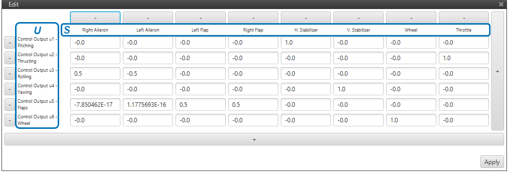
\(\boldsymbol{US}\) Matrix for a Fixed-Wing aircraft
Note that the fixed-wing example shown above has only one \(S\) only. Now, some more practical examples of real configurations – with more complex \(SU\) matrices – will be presented in order to complement the above explanation.
\(\boldsymbol{SU}\) of a Flying Wing
Flying wings are tailless aircrafts, i.e. their only control devices are ailerons and a motor. So both the longitudinal (pitching) and lateral (rolling) control of the platform have to be controlled only with the ailerons – known as elevons in this kind of configurations. Therefore, two actuator channels \(S\) (left and right ailerons) will have to incluence two control outputs \(U\). When working like elevators, the elevons move together; when working like ailerons, one moves up as the other one moves down – this dual behaviour ir highlited in red in the Figure below.
\(SU\) Matrix of a Flying Wing
\(\boldsymbol{SU}\) of a V-Tail Aircraft
The V-tail aircraft presented next has the same platform structure as the one shown above except for one difference: the tail of the aircraft is at an angle (v-shaped). That implies that pitching and yawing are controlled by two control surfaces, while for a regular congfiguration they are controlled by one separate control surface each. These control surfaces are know as ruddervators. When working like elevators, the ruddervators move together; when working like rudders, one moves up as the other one moves down – this dual behaviour ir highlited in red in the Figure below.
Regarding the rest of the actuators \(S\), each of them only influence one single control output \(U\)– see the \(SU\) matrix below.
\(SU\) Matrix of a V-Tail Aircraft
\(\boldsymbol{SU}\) of a Quadcopter
When it comes to a multicopter the \(SU\) matrix definition is not straigthforward. Here we consider a quadcopter because it is the simplest of cases. Therefore, as its name suggests, it has 4 motors. The convention of the motor order in a quadcopter is the following: motor 1 is placed on the front right of the quadcopter, and the rest of them are placed following a clock-wise oder – see the Figure below.
When defining the \(SU\) matrix of a quadcopter with symmetrical geometry:
Control output \(U\): thrusting will require all 4 motors to increise their rpms the same amount.
Control output \(U\): pitching will require for motors 1 and 4 to increase their rpms one particular amount, and motors 2 and 3 to decrease their rpms that same amount.
Control output \(U\): rolling will require for motors 1 and 2 to increase their rpms one particular amount, and motors 3 and 4 to decrease their rpms that same amount.
Control output \(U\): yawing will require for motors 1 and 3 to increase their rpms one particular amount, and motors 2 and 4 to decrease their rpms that same amount.
In multicopters, specially for symmetrical geomtries, it is interesting to introduce the same influence values for the pitching and rolling control channels. That is so because when tunning the control gains (control parameters) they are usually very similar in both control channels.
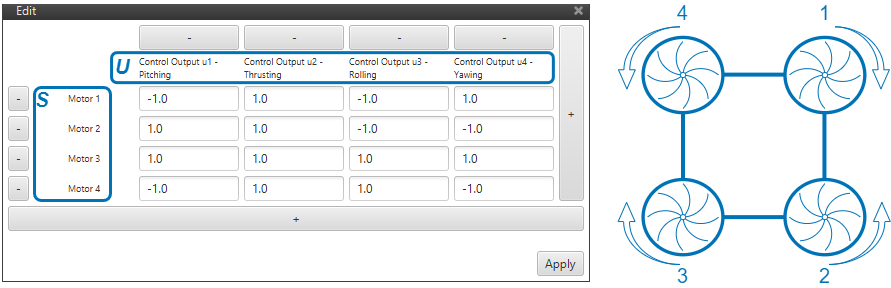
\(SU\) Matrix of a Quadcopter
If the considered quadcopter wouldn’t have symmetrical geometry, the \(SU\) matrix needs to account for the lack of symmetry. In the Figure below, one can see that motors 1 and 4 are further ahead of the center of gravity (CG) of the platform than motors 2 and 3.
For a hover maneouvre, the desired pitching moment is 0. Assuming the latter, i.e. the sum of all existing moments equal to 0, one finds the following relation \(T_{back} = 1.5 \cdot T_{front}\), where \(T\) represents the force generated by the motors.
Therefore, one needs to define an influence value for the motors in the front (1 and 4) and then, multiply that same value by \(1.5\) for the motors in the back (2 and 3). One could choose the values \(1\) and \(1.5\), but in order for the pitching and rolliing values to be similar, \(0.8\) and \(1.2\) are a better option – and they also satisfy the above relation.
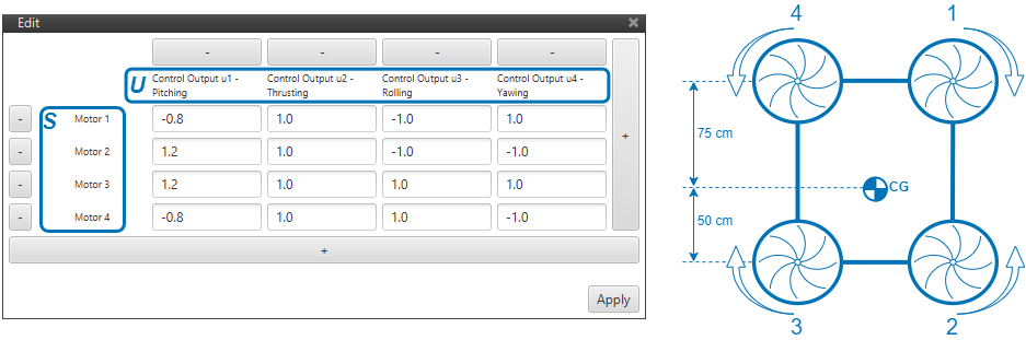
\(SU\) Matrix of a Quadcopter (non-symmetrical geometry)
\(\boldsymbol{SU}\) of a VTOL Aircraft
Finally, a vertical take-off and landing (VTOL) aircraft configuration is covered. Main features of the aircraft are: V-shaped tail, a wing with ailerons only, one motor for plane mode, and 4 motors for quadcopter mode (VTOL). The recommended strategy for this kind of platform is to create 4 control channels \(U\) for the plane mode and 4 control channels \(U\) for the quadcopter modes.
The \(SU\) matrix of the VTOL aircraft looks like:
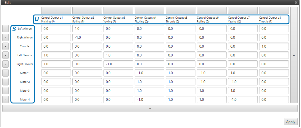
\(SU\) Matrix of a VTOL Aircraft