Operation
Types of operations
Veronte Autopilot 4x is an advanced system designed to enable the operation of autonomous vehicles, offering three control modes: automatic, assisted, and manual. This versatile autopilot can be used in both uncrewed and manned vehicles, integrating a FLY-BY-WIRE system that ensures precise and safe control at all times.
One of the main advantages of the Veronte Autopilot 4x is its configurability, allowing it to be adapted for different operational needs. Depending on the chosen configuration, the system can handle various types of takeoff, such as runway or catapult launches, among others.
Veronte Ops is the Veronte application dedicated to operating the system, providing an intuitive interface for mission management and monitoring. Additionally, for more flexibility, the system can also be operated through VCP (Veronte Communication Protocol), enabling the creation of custom control stations or integration with onboard mission computers for more specific or advanced applications.
In summary, Autopilot 4x stands out for its versatility, ease of integration, and customization options, offering a comprehensive solution for a wide range of autonomous vehicle applications.
In addition, for the different types of operations, the user may need to make different connections, configurations and/or integrations with external devices with Veronte Autopilot 4x. Therefore:
Examples of how to integrate Autopilot 4x with external devices such as datalinks are detailed in the Datalinks - Integration examples section of the present manual.
Please take a look at these sections for further explanations.
This section summarizes a list of possible options to operate an Autopilot 4x in different situations.
Tip
Most of the following diagrams can be used independently or combinated, to create redundant systems or backup solutions.
Operation Architectures
Veronte Autopilot 4x allows for a wide variety of communication and control solutions to adapt to each mission and platform specifications.
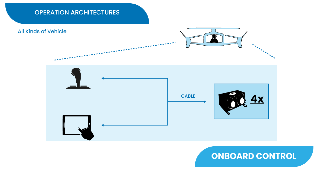
Onboard Control Setup
4x allows to control aircrafts (such as eVTOLs) by pilots on board in a flight deck. Pilots can use as controller joysticks, computers, tablets or any device able to communicate through PPM, CAN Bus, RS232 or RS485.
Remote Control Setup
The following image shows the standard Veronte System Layout for remote operation.
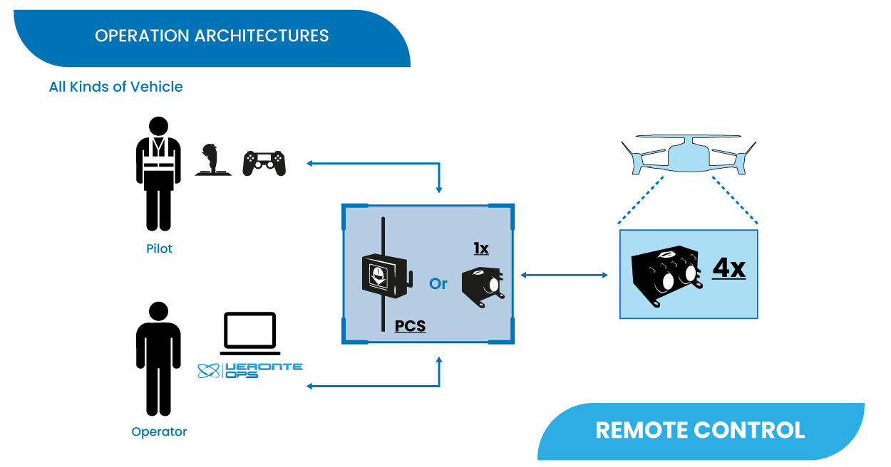
In the standard remote layout, an Operator (Internal Pilot) controls the UAV from the Ground Station using Veronte Ops.
Additionally, a Safety Pilot (External Pilot) is connected to the Ground Station using a radio controller. The stick commands are read by the Ground Unit and re-routed to the Air Unit. The Safety Pilot is able to take control of the flight at any point using an automation.
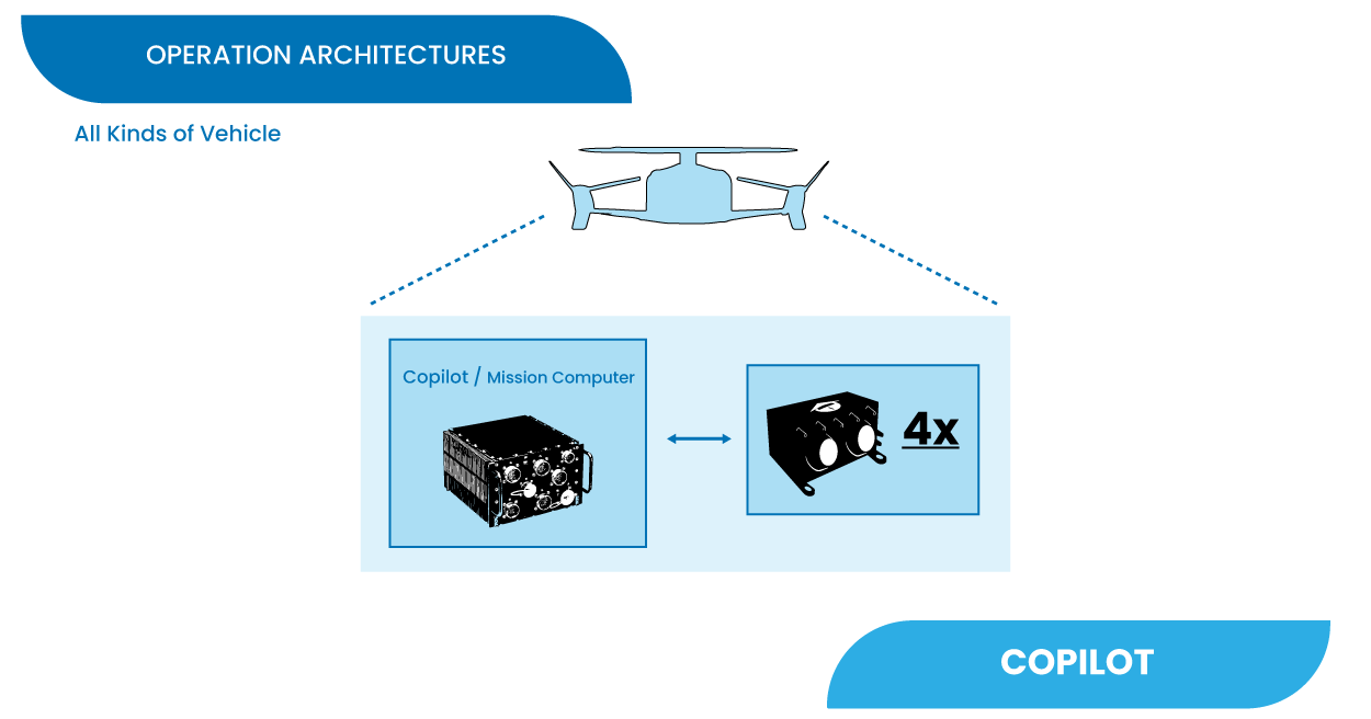
Copilot Control Setup
Veronte system allows integration with onboard mission computers for more specific or advanced applications.
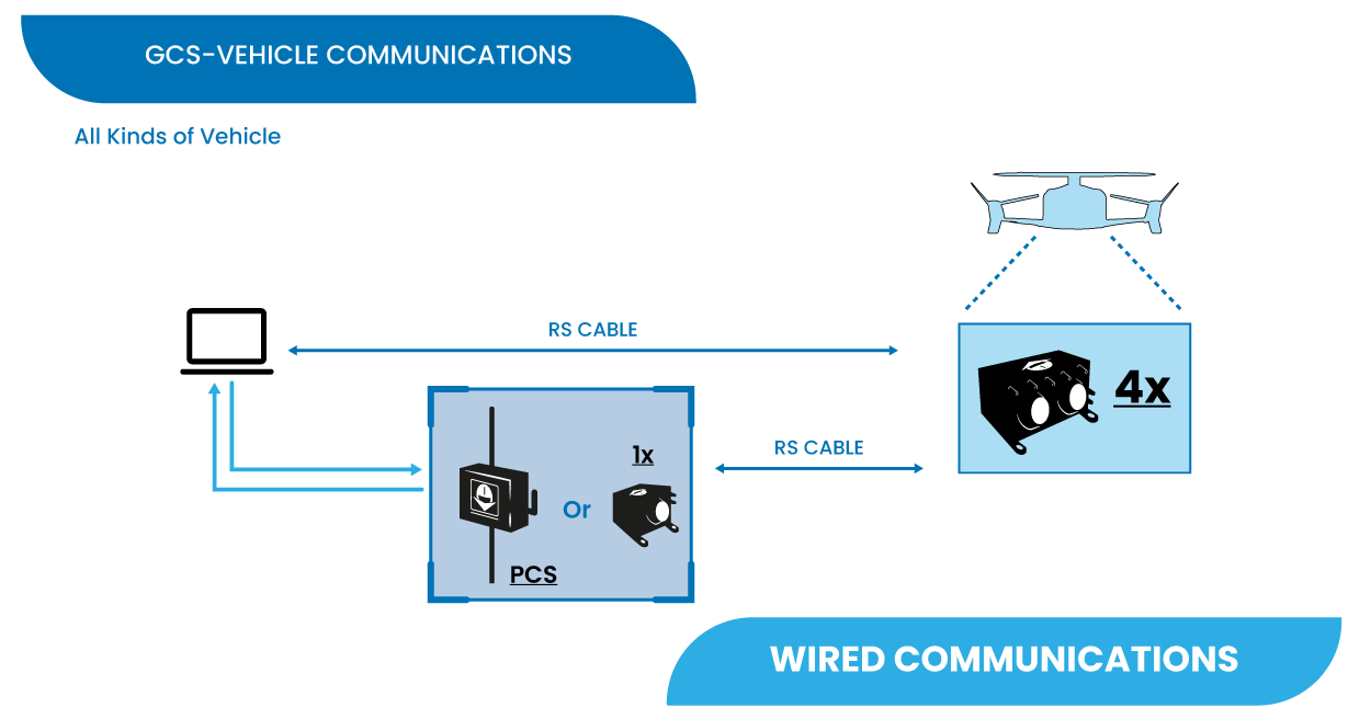
GCS-Vehicle Communications
The following are some examples and possible solutions for establishing communication between the ground control station and the vehicle.
LOS Communications
The following diagram shows the different options of GCS and in-vehicle solutions to establish correct Line of Sight (LOS) communications between them.
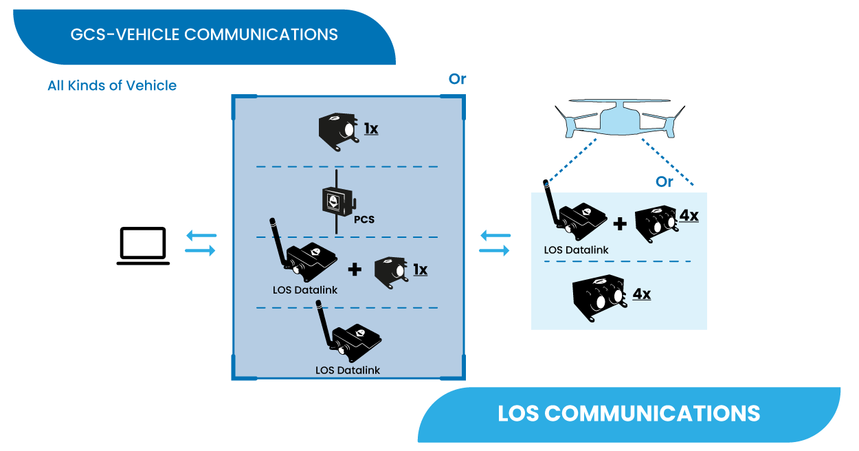
Depending on the requirements and needs of their mission, users can choose as GCS:
Autopilot 1x with its internal LOS module
PCS
Autopilot 1x with an external LOS Datalink
LOS Datalink
And on the vehicle side:
Autopilot 4x with its internal LOS module
Autopilot 4x with an external LOS Datalink
BLOS Communications
Veronte Cloud enables secure and efficient Beyond Line of Sight (BLOS) communication between the autopilot onboard a vehicle and the control station. It supports various communication methods, offering a flexible architecture to suit different operational requirements:
Autopilot 4x Internal Module: Embedded 4G module within Autopilot 4x.
LTE/4G/5G Module: External LTE module for wireless communication.
Satcom Module: Satellite communications device for global coverage.
Starlink: High-bandwidth, global communications module.
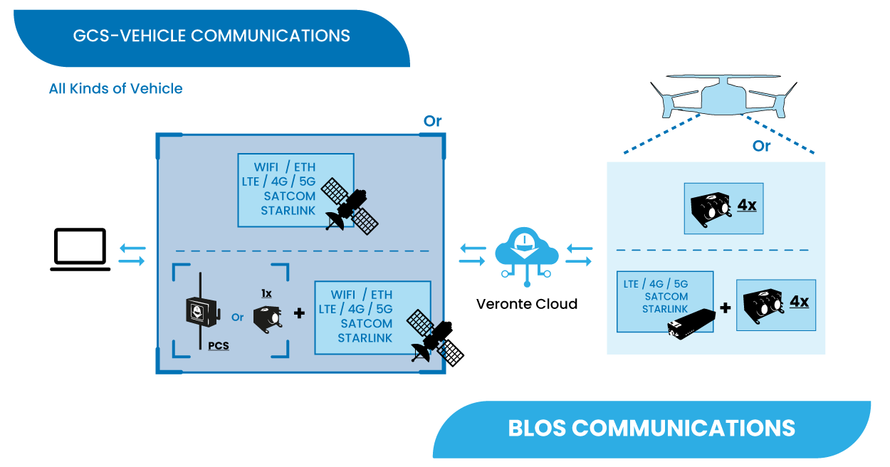
These communication methods can be used both at the ground control station and onboard, enabling seamless switching between methods or simultaneous use for redundancy and enhanced reliability. They can also be combined to meet specific project requirements.
Control Station Connectivity Options
The control station connects to Veronte Cloud through two primary methods:
Option A: Direct PC Internet Connection
The control station PC connects directly to the Internet for communication with Veronte Cloud. This can be achieved using any available means of Internet communication:
Ethernet or Wi-Fi
LTE/4G/5G
Satellite Communication (Satcom)
Starlink
Option B: Connection via Veronte PCS/4x
The control station PC connects to the Veronte PCS/1x module, which manages the connection to the BLOS datalink module. The PCS/1x module supports:
Its internal 4G module for direct connectivity.
External communication modules (LTE/4G/5G, Satcom, Starlink, etc.).
This setup enhances communication reliability by leveraging Veronte’s dedicated hardware for connection management and enabling the use of additional sensors integrated within the PCS/1x module.
Onboard Connectivity Options
For onboard BLOS communications, Veronte Autopilot 4x system offers two main methods:
Option C: Internal 4G Module in Veronte Autopilot 4x
Autopilot 4x comes equipped with an internal 4G module that connects directly to Veronte Cloud. This option is compact and does not require additional external hardware.
Option D: External Module Connected to Autopilot 4x
The autopilot can integrate an external communication module (LTE/4G/5G, Satcom, Starlink, etc.) to enable BLOS communication with Veronte Cloud. This provides flexibility and allows for customization based on specific mission or environmental needs.
Wired Communications
For operations where the control station is directly connected to the onboard autopilot by cable.
GCS Interface
This diagram represents some of the many ways to establish communication between the different parts of a Ground Control Station setup.
Note
In a Ground Control Station setup there is usually a PC on one side and an Autopilot 1x with its internal LOS module, an Autopilot 1x with an external LOS Datalink or a PCS on the other side.
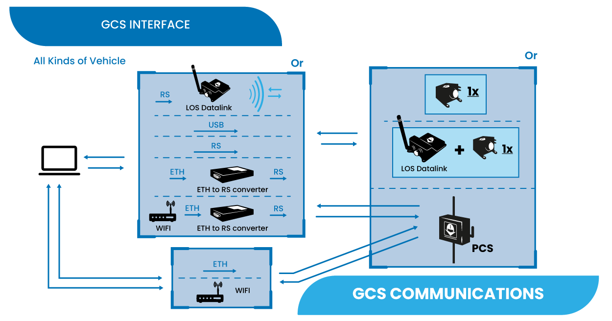
Direct connection
The PC can directly connect a PCS via USB, RS, Ethernet or Wifi.
The PC can directly connect an Autopilot 1x with its internal LOS module or Autopilot 1x with an external LOS Datalink via USB/RS.
Combined connections
Below are different connection methods that enable communication between the PC and an Autopilot 1x with its internal LOS module, an Autopilot 1x with an external LOS Datalink or a PCS via an additional device:
PC connected via RS to a LOS Datalink, establishing a datalink connection to the other side of the GCS setup.
Connection through an Ethernet-to-RS converter, i.e. Ethernet on the PC side and RS on the other side.
The PC connects via wifi and the wifi modem then communicates with the other side of the GCS setup through an Ethernet-to-RS converter.
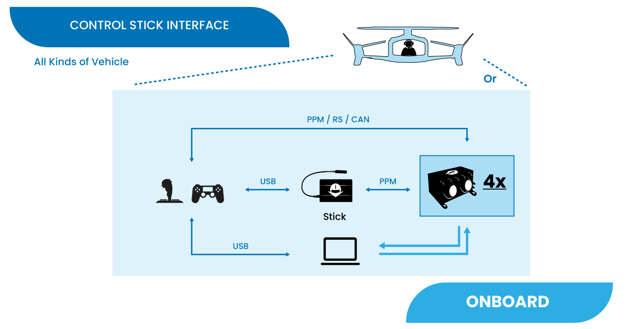
Control Stick Interface
This section presents the different types of manual control from stick to the onboard autopilot.
Veronte allows for a wide variety of pilot interface solutions in order to interact with manual flight modes, assisted flight modes (arcade) or payloads.
Remote Control Stick
A wide variety of controllers can be used to pilot manually aircrafts, such as RC transmitters, pedals, sticks or buttons. Veronte software allows the use of any device that is detected as a remote controller by the operative system
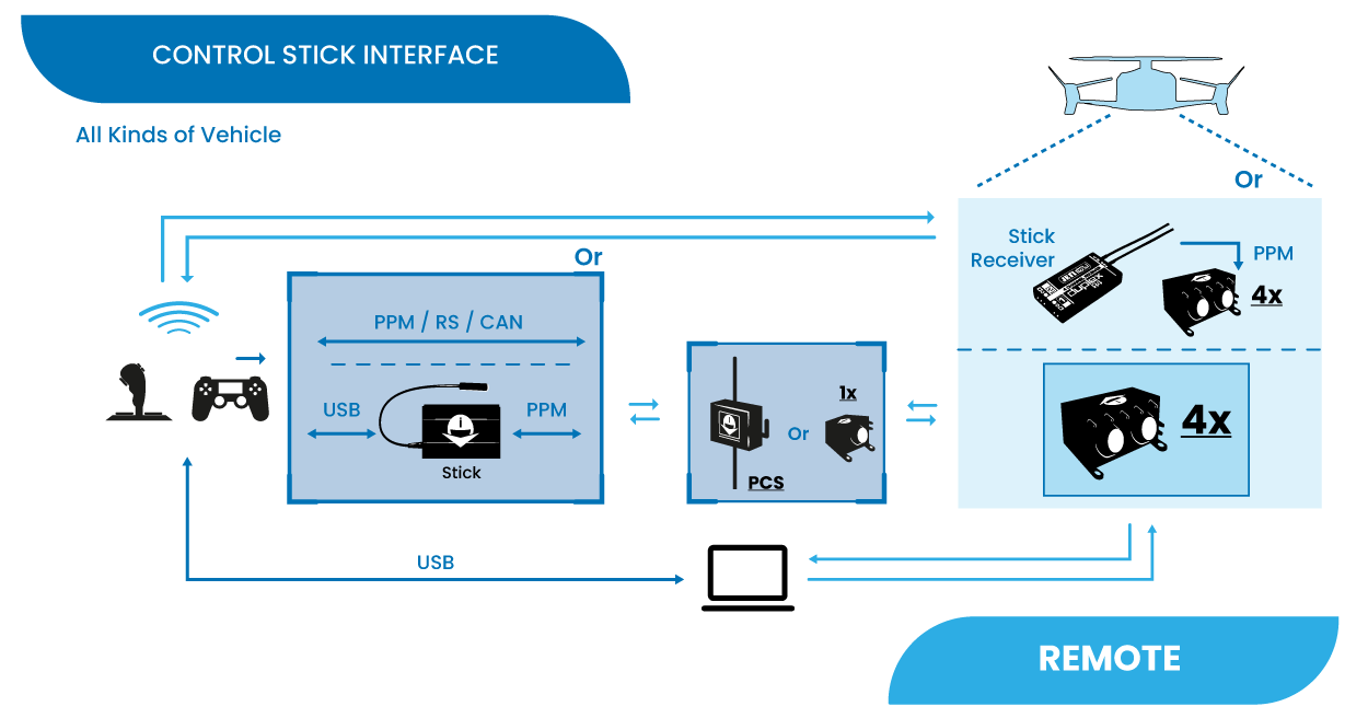
Although the most common way of control is to directly connect a stick via PPM, RS or CAN to a control station (PCS/1x) which then communicates with the onboard autopilot,
It is possible to establish a link connection between a stick and a stick receiver integrated in the vehicle, which is connected via PPM to Autopilot 4x.
This allows for a backup manual channel when there is a main channel loss and an emergency manual landing is needed. Recommended for initial developement stages where automatic landing phases are not defined yet.
A Veronte Stick allows the connection of USB sticks to a control station (PCS/1x), converting USB to PPM. Then, the GCS communicates with the onboard autopilot for control.
A USB stick can be connected directly to the PC to establish communication with the onboard autopilot for control.
Onboard Control Stick
In operations with pilots onboard in a flight deck (such as eVTOLs), the sticks can directly control the vehicle’s Autopilot 4x.
Some examples are:
To directly connect a stick via PPM, RS or CAN to the autopilot.
To use a Veronte Stick that converts USB to PPM, allowing connection between USB sticks and the autopilot.
Connect a USB stick to a PC which establishes communication with the autopilot.
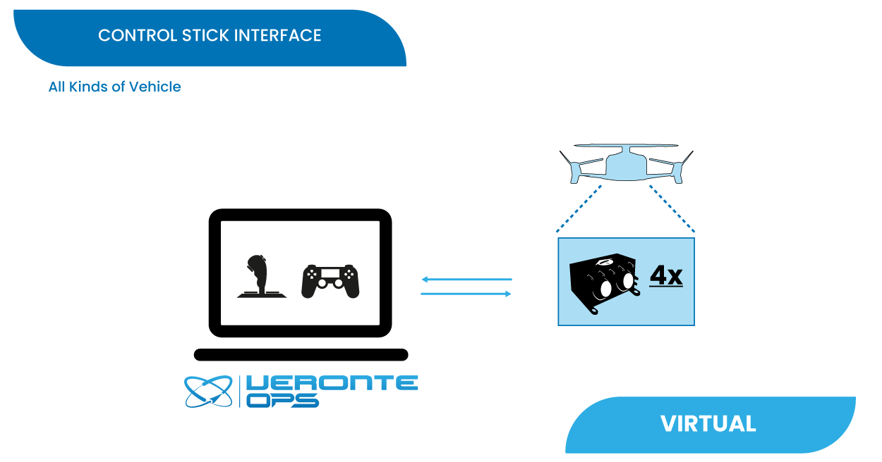
Virtual Stick
The Virtual stick feature allows to integrate as a stick controller any device that can interface with Autopilot 4x (RS232, RS485, ADC, CAN…) and can provide control reference values.
While the configuration is slightly more complex, this feature allows using a wide variety of devices as flight control interfaces.
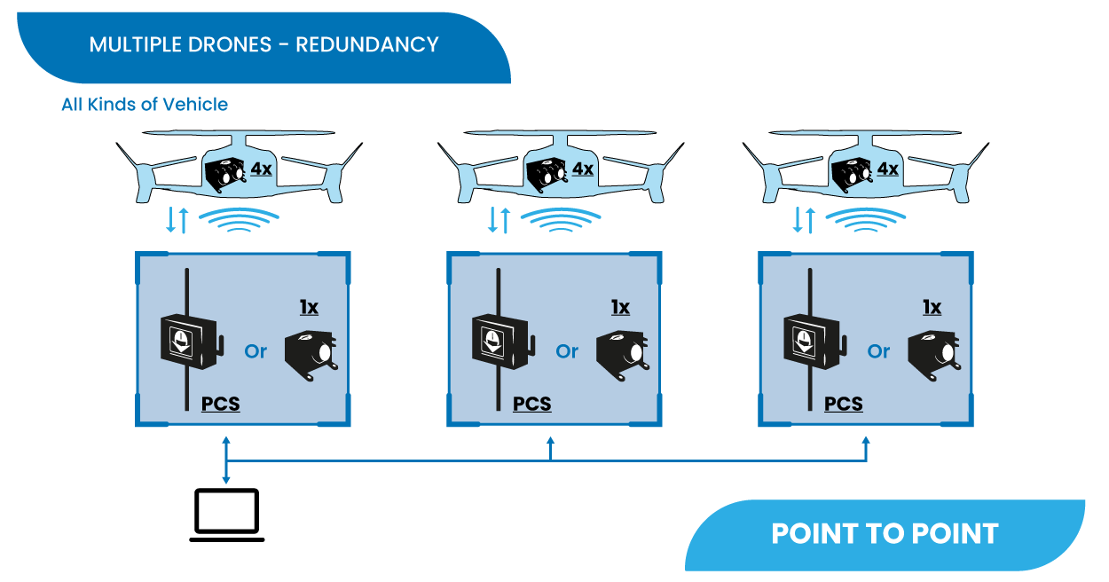
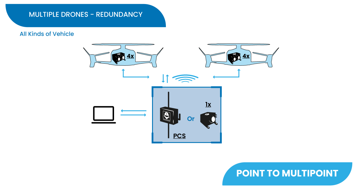
Multiple Drones/GCS - Redundancy
Due to Veronte’s modular configuration, it is possible to integrate several onboard and ground units within the same network.
Note
Users are free to combine the different multiple drones solutions with the multiple GCS solutions.
Multiple Drones - Point to Point
Standard multiplatorm setup.
Multiple Drones - Point to Multipoint
Managing several platforms with a single radiolink.
Multiple GCS
For long range operations with several LOS stations.
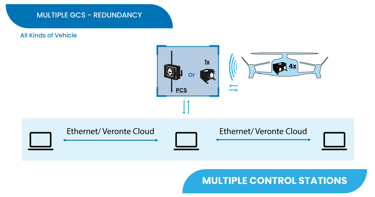
For remote solutions with LOS backup operator, Veronte Cloud allows the connection between PCs.
To correctly establish communication between the different PCs via Ethernet the following steps should be carried out:
Make the physical connection with ethernet cables, the two different types of ethernet cables can be used:
Straight-Throught
Connect each PC to an ethernet switch with its Straight-Through ethernet cable (i.e. users will need 2 cables).
Crossover
Connect the PCs directly to each other with a crossover ethernet cable.
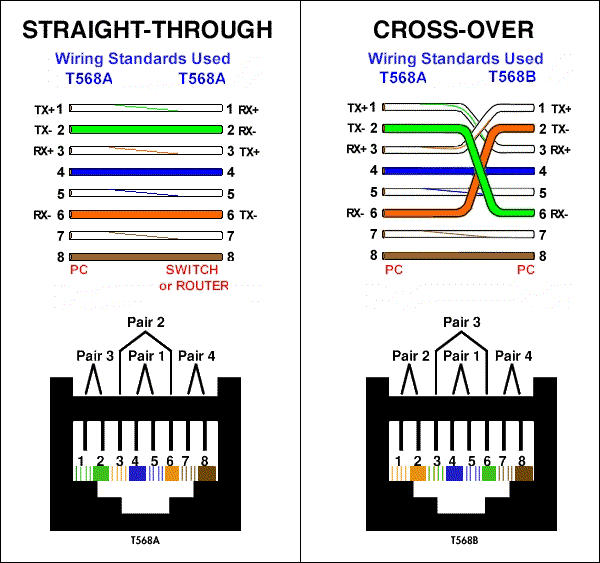
Straight-Through vs Crossover cables
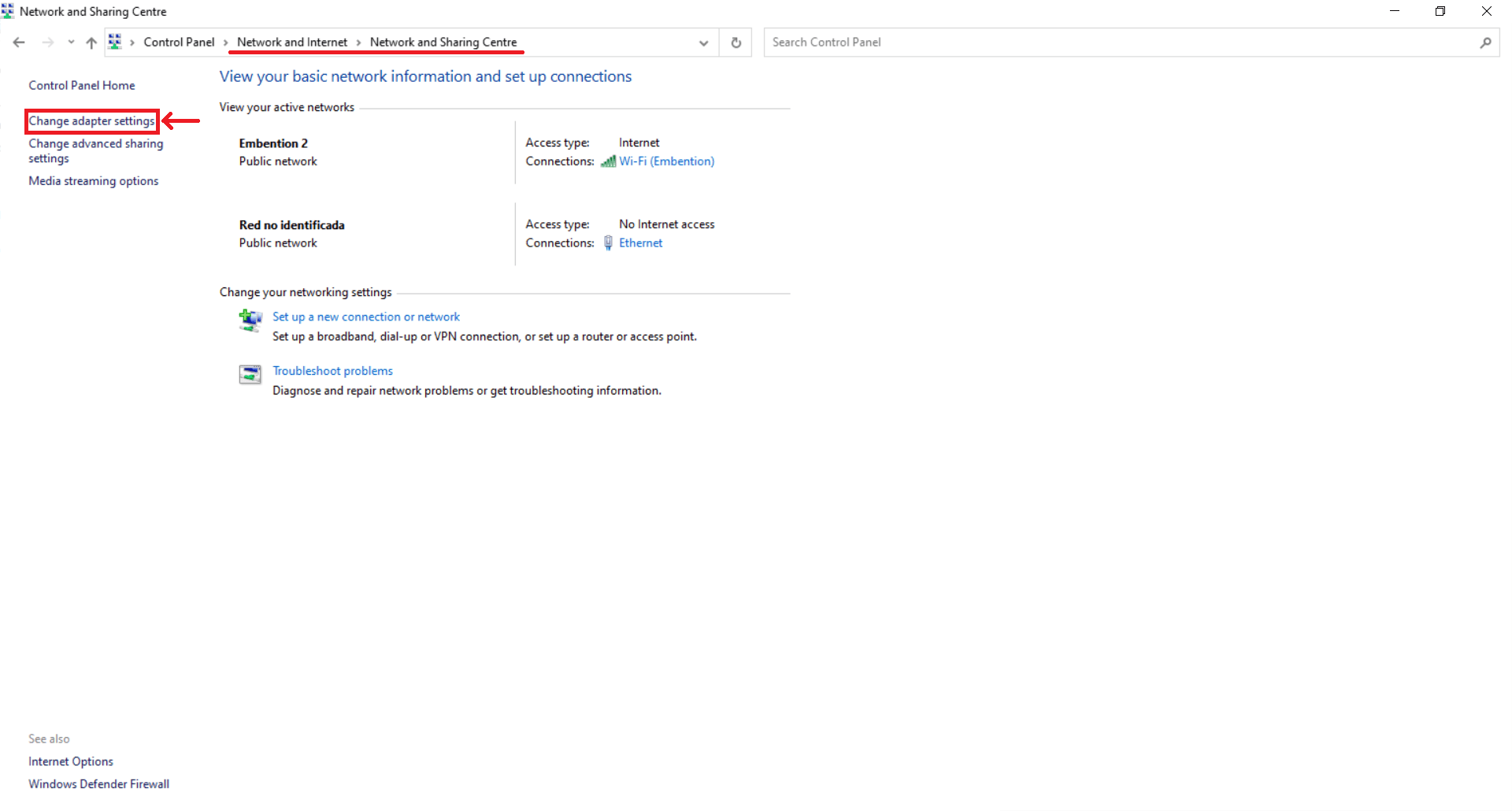
On each PC, change the ethernet adapter settings to a static IP so that both are on the same subnet. To do this:
In the Control Panel, go to Network and Internet.
Open Network and Sharing Centre menu and click Change adapter settings.
Ethernet connection 1
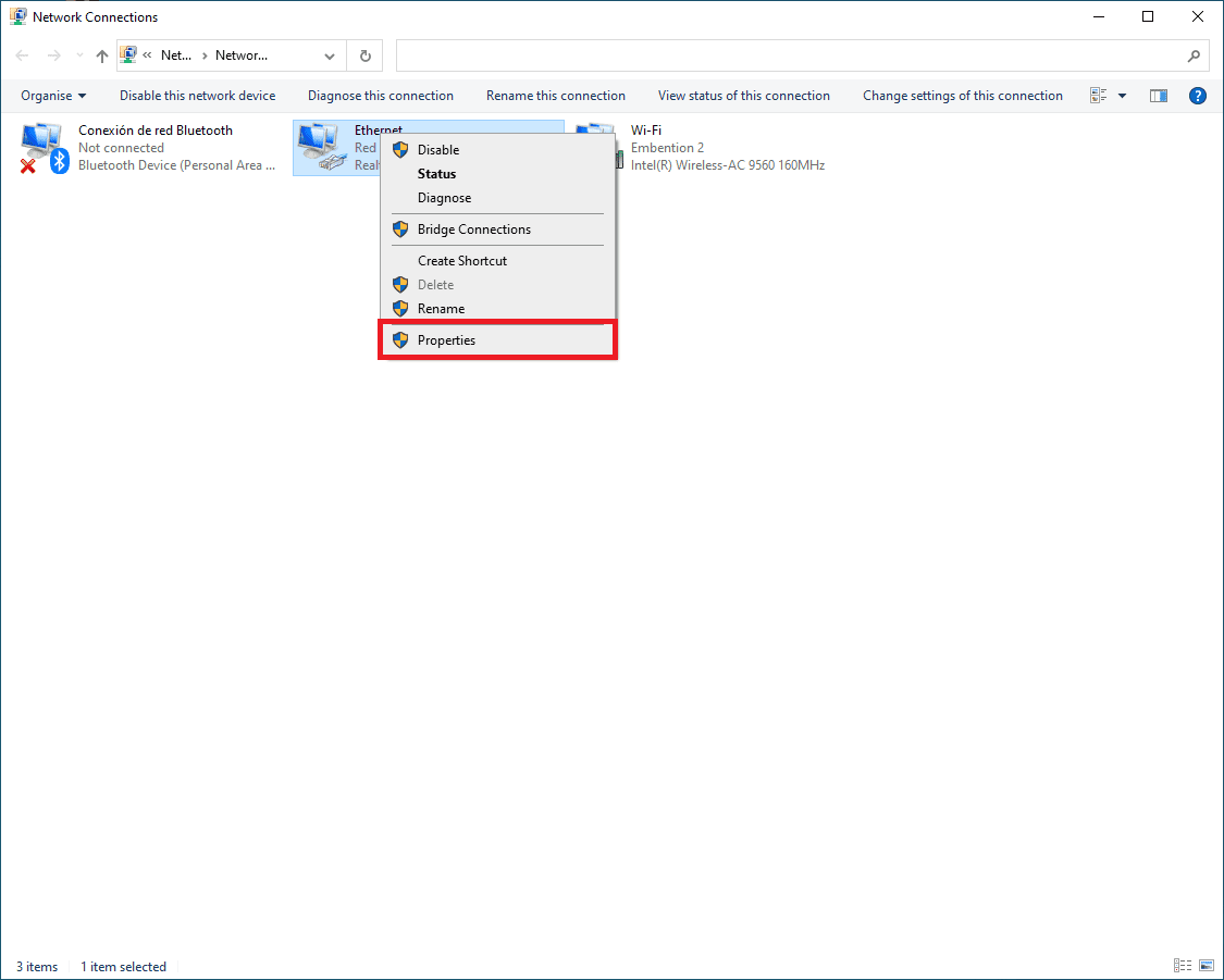
Select Local Area Connection, right click, and select Properties.
Ethernet connection 2
Select IPv4 and click Properties.
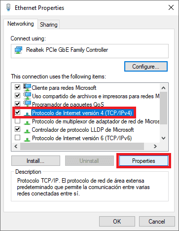
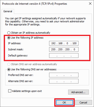
Ethernet connection 3
Set IP address to a static IP (e.g. 192.168.0.100) and Subnet mask to 255.255.255.0. Click OK.
Important
If on this PC the IP address is set to 192.168.0.100, on the other PCs, the IP address must be set to 192.168.0.XXX (e.g. 192.168.8.234), so that they are on the same subnet.
Ethernet connection 4
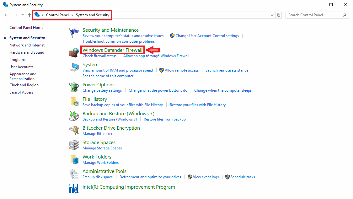
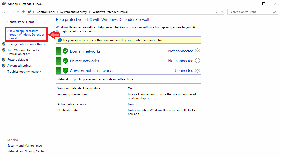
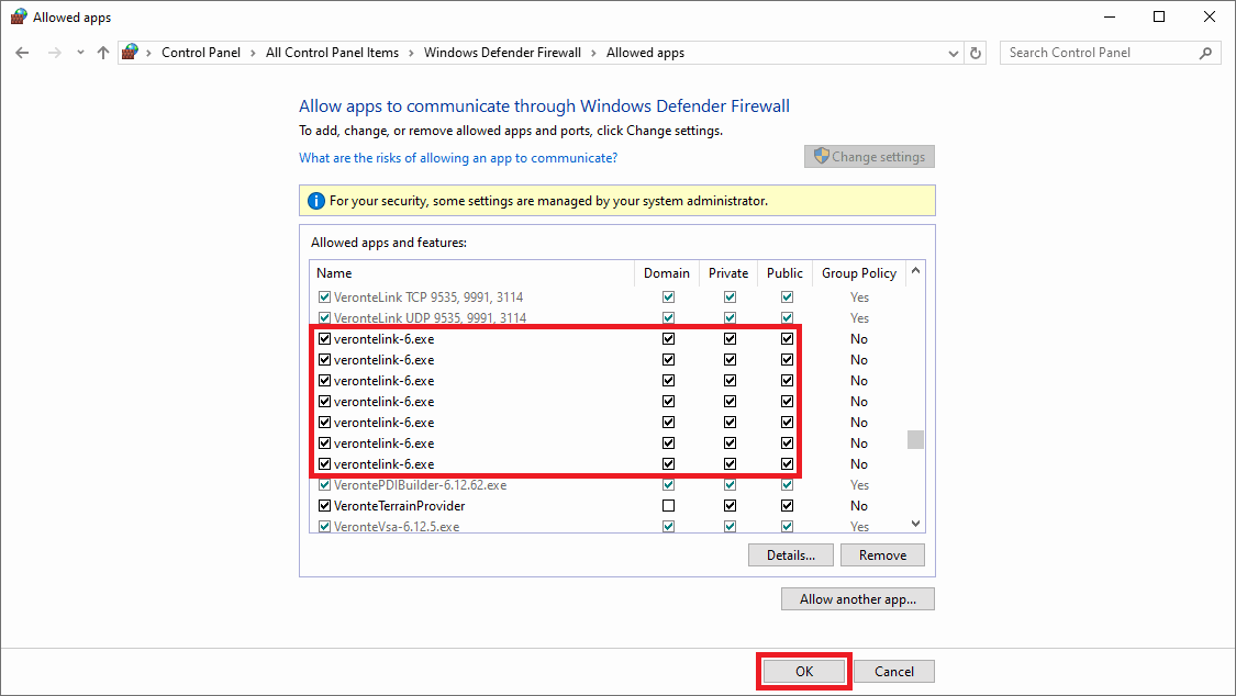
Allow VeronteLink to go through the Firewall on the PC that will run it, hereafter PC primary. To do so:
On the PC secondary, in Veronte Ops change the Veronte Link Host option setting to the IP of the PC primary. To do this:
Open Veronte Ops.
In the Status bar, click the arrow on the right of the bar to display a drop-down menu.
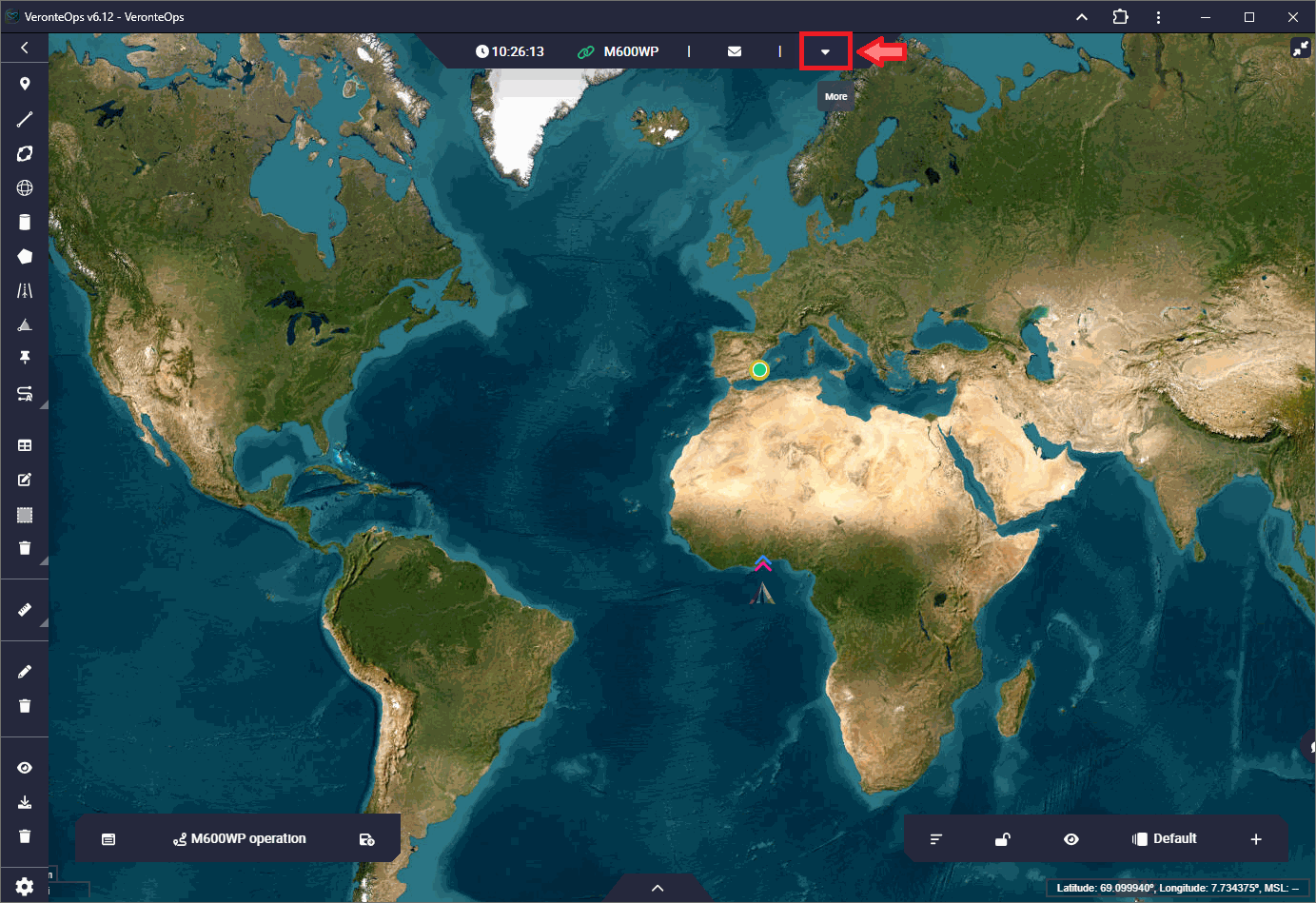
Veronte Ops - Status bar
In it, open the Setup menu.
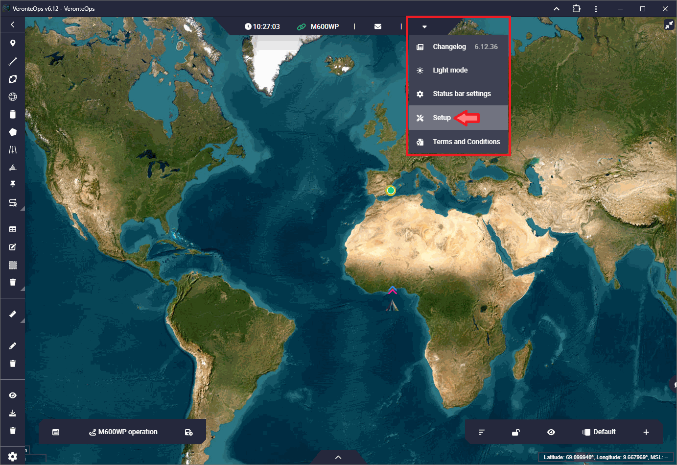
Veronte Ops - Setup menu
Next, go to the Veronte Link Host settings.
Change the IP localhost to the IP of the PC primary.
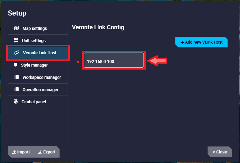
Veronte Ops - Veronte Link Host settings
For more information on this settings, refer to the Setup - Veronte Ops configuration section of the Veronte Ops user manual
Finally, Autopilot 1x connected to the PC primary should be seen in the Veronte Ops open on this PC, as well as on the PC secondary.
If users have any problems when trying to connect Veronte Ops to Veronte Link, refer to the Connecting to Veronte Link - Troubleshooting section of the Veronte Ops user manual.
If after following the steps described above users are not able to operate in this way, please contact support team by opening a Ticket in your Joint Collaboration Framework.