Software Installation
Connections to computer
Internal autopilots
Each Veronte Autopilot 1x must be connected to a computer individually to configure it. The Management Board must also be connected individually.
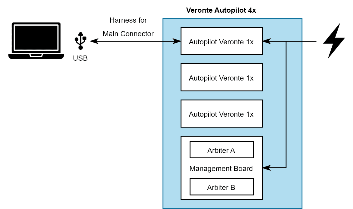
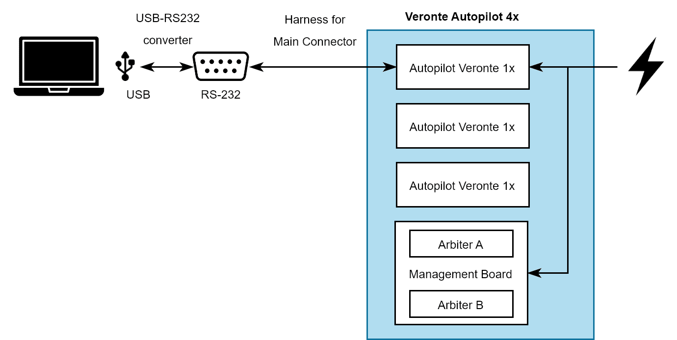
There are two ways to connect a Veronte Autopilot 1x to a computer: USB or serial with RS-232. Both options require power supply for the connected Autopilot 1x. Attach the 4x Redundant Harness to the Connector 4 to connect a computer and any Autopilot 1x.
Note
To use the RS-232 connection with a computer, an USB-RS232 converter is required.

USB connection to Autopilot 1x

Serial connection to Autopilot 1x
If there is any doubt about electrical connections, check the Main Connector pinout and the Arbiter Connector pinout in this manual.
Management Board
Autopilot 4x with hardware version 1.8 has a Management Board, which is composed by 2 arbiters. Both arbiters have the external communications separated and both require configuration. Hence, Management Board requires two differents connections to a computer, each one configuring a different arbiter. Previous hardware versions only had one arbiter, requiring only one connection and configuration.
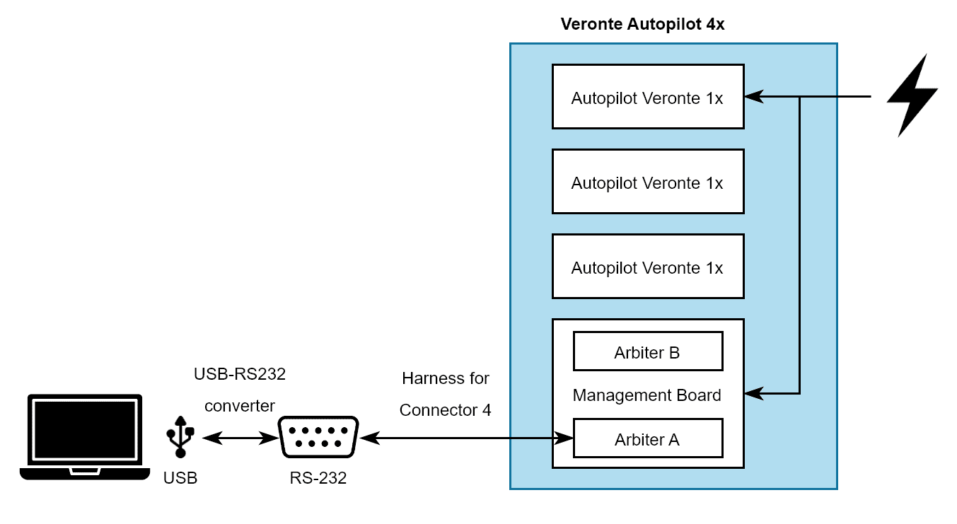
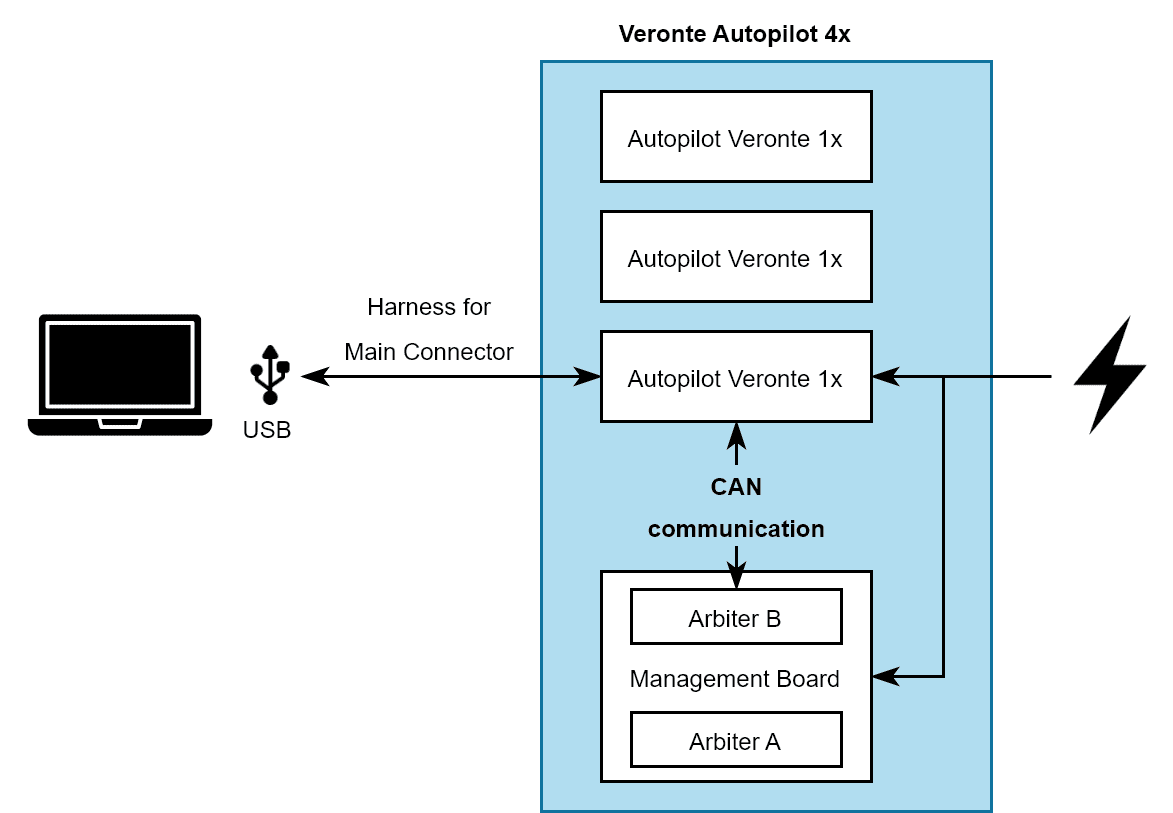
Arbiter A can be connected to a computer via RS-232 or CAN (through one internal 1x).
To connect a computer to Arbiter A via RS-232, the connection is as follows:

Arbiter connection via Serial
Another way to connect a computer to arbiter A is to use an Autopilot 1x as a CAN tunnel, so messages travel through intenal CAN connections. Nonetheless, an Autopilot 1x requires a configuration to perform tunnel communications, which is explained in the Arbiters communication - Integration examples section of the 1x PDI Builder user manual.
Arbiter B does not have RS-232 port, hence the only way to connect B with a computer is through CAN, as explained before.

Arbiter connection via CAN tunnel
Important
Each arbiter will be identified by software applications as a different device.
Software manual
To install the required software and configure each Veronte Autopilot 1x and the arbiters, read the 4x Software Manual.
