PID Controller
Classical PID controller. The values for each one of the elements (proportional, integral, derivative and so on) can be changed directly on the screen.
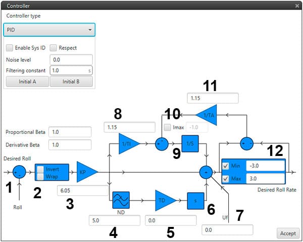
Focusing on the PID structure the next figure and table describe all its elements and what means each one of them.

PID Architecture
Value |
Description |
|---|---|
1 |
Measure |
2 |
Invert: Change error sign/Wrap: Wrap to pi [-π, π]/It is used in some angular variables (radians) for avoiding numerical errors on the –π to π change and keep continuity of the error signal |
3 |
Proportional gain |
4 |
Discrete filter parameter |
5 |
Derivative time parameter |
6 |
Derivative gain |
7 |
Constant value added to output (Feedforward Control) |
8 |
Integral gain |
9 |
Inverse integral time parameter |
10 |
The maximum value of integral admitted |
11 |
Anti-windup parameter |
12 |
Output bounds |
Output values for PID controller refer to virtual control channels, units must coincide with servo trim configuration settings.
PID diagram represents the following PID model:

PID Mathematical Model
Kp=proportional gain
Ti=Integrator time
Td=Derivative time
N=Derivative filter constant
For the derivation and integration models, Backward Euler and Trapezoidal (respectively) models have been integrated:
Backward Euler:
PID Mathematical Model - Backward Euler
Trapezoidal
PID Mathematical Model - Trapezoidal
τ= Td/N where τ is the time constant on a first order low pass filter (LPF). In Laplace notation:
PID Mathematical Model - Laplace
