Connection
To stablish the connection between SIL Simulator and 1x PDI Builder to build/open a configuration, the following steps should be followed:
Open Veronte Link and configure it for a UDP connection. For more information, see the UDP connection -> Integration examples section of Veronte Link user manual.
If using Veronte Console, the UDP address needed to be configured in Veronte Link must be: 127.0.0.1.
If SIL Simulink is used: The required address to be configured in Veronte Link must match the UDP address specified in the Simulink Blocks.
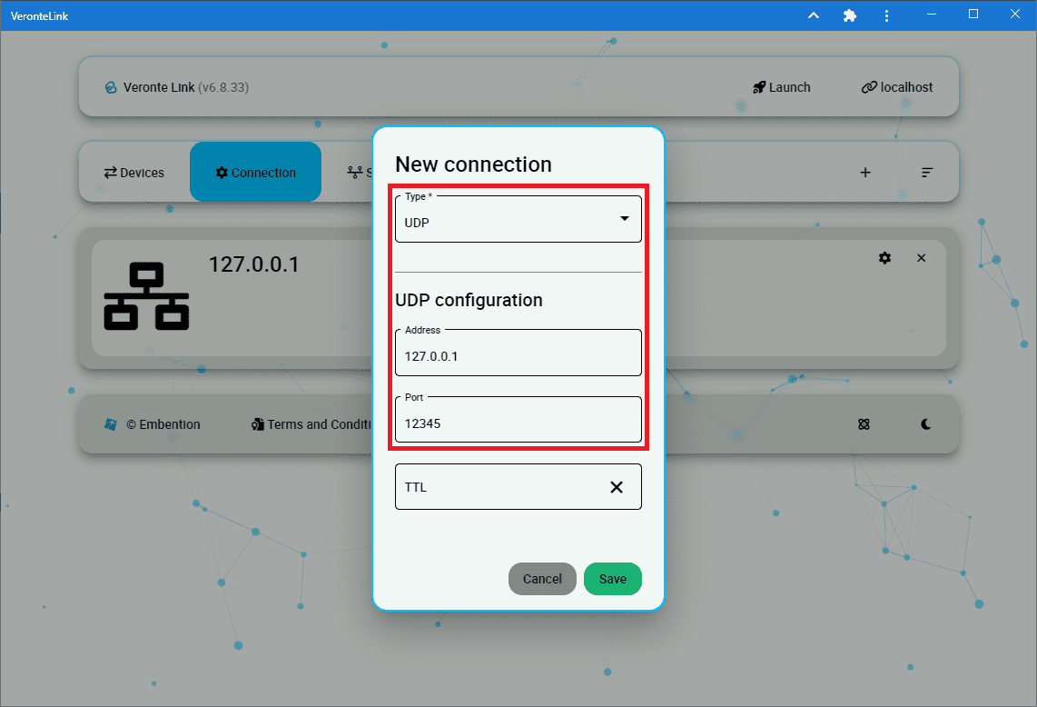
Veronte Link - UDP configuration for Veronte Console
Execution: As explained previously, SIL Simulator can be executed in 2 different ways, through a standalone Veronte Console Executable or through SIL Simulink.
Either way, both methods require:
VeronteDLL.dll: Dynamic Link Library containing the Veronte AP code.
Veronte_SD_Image.img: Veronte Autopilot 1x SD image.
These files must be placed in the root directory of SIL (the unzipped SIL 6.8 folder).

Image and Veronte DLL files in the unzipped SIL folder
If any of the above files are located in a directory other than the standard unzipped SIL 6.8 folder, it is possible to specify a different path by creating a file named “dll_config.vcfg” which must be placed in the unzipped SIL 6.8 folder.
Within this file, the absolute path to the DLL and Image file must be provided as follows:
\dll C:\Users\user\Folder\VeronteDLL.dll\image C:\Users\user\Folder\Veronte_SD_Image.img
VERONTE CONSOLE:
If the files are not located in the unzipped SIL folder, the path described above, can be passed as arguments to the windows command, for this:
Open windows command \(\Rightarrow\)
cmdPass to it:
VeronteConsole.exe \dll C:\Users\user\Folder\VeronteDLL.dll \image C:\Users\user\Folder\Veronte_SD_Image.img
After this, when the user runs VeroteConsole.exe, if everything has been correctly configured, it should look like this:

Veronte Console
SIMULINK:
Create an Ethernet connection in Simulink Blocks:
Add a UDP serial communication block and connect it to USB data and length.
Add a second UDP serial communication block and connect it to the USB output of veronte.

UDP Blocks
Configure the desired destination port.

Destination UDP Port
Run the Simulink model to simulate the Autopilot 1x information.
Check that the autopilot appears in Veronte Link as Connected and Ready:
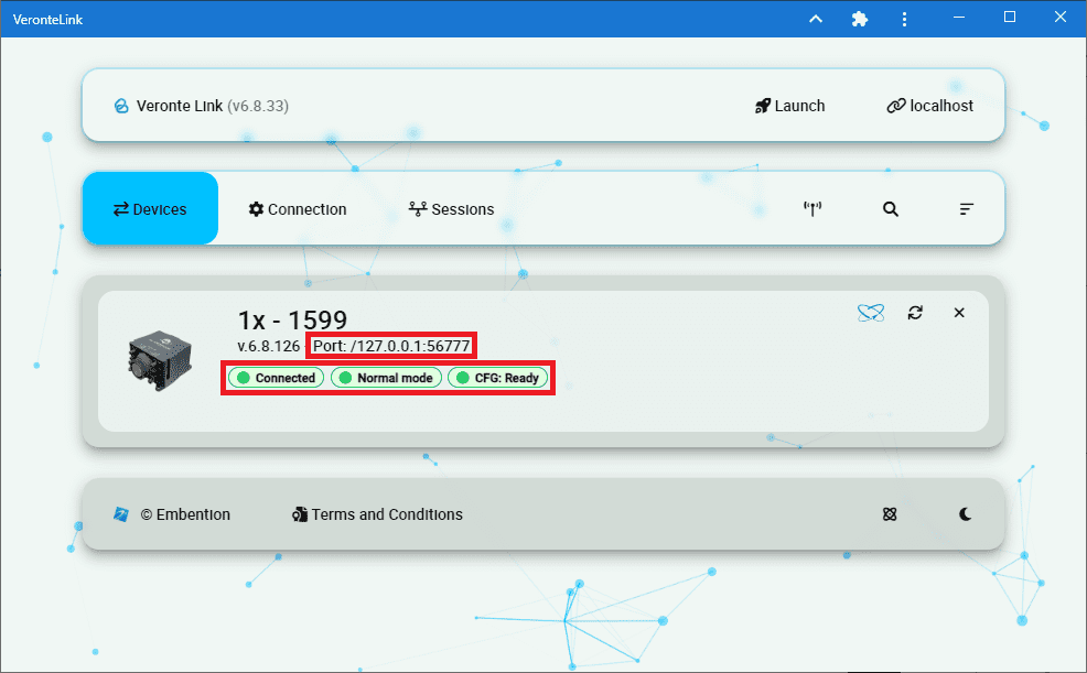
Veronte Link
Important
In the first generation of the Veronte Autopilot 1x, it is possible that its status is: ‘Maintenance Mode’ and ‘CFG: Failed to load’.
This is because the Autopilot PDI has no productionLine calibration. This is fixed by uploading the SIL.ver file through 1x PDI builder.
The calibration uploaded through the SIL.ver file is saved in the Veronte_SD_Image.img, so there is no need to upload this file again.
Open 1x PDI Builder and select the 1x Autopilot. For more information on this software, see 1x PDI Builder user manual.

1x PDI builder
Warning
In this version it is not possible to upload the configuration (PDI files) while running the Veronte DLL with SIL Simulink.
Therefore, if the user is using SIL Simulink for the simulation, he/she must switch to Veronte Console execution to upload the configuration, and then switch back to running SIL Simulink.