GNSS
GNSS receiver ports (there are 2 ports -GNSS1 and GNSS2-) expect to receive an array with the following information:
Fix status
Fix type
0: no fix
1: dead reckoning only
2: 2D-fix
3: 3D-fix
4: GNSS + dead reckoning fix
Latitude
Longitude
Altitude
Horizontal accuracy
Vertical accuracy
North Velocity
East velocity
Down Velocity
Speed Accuracy
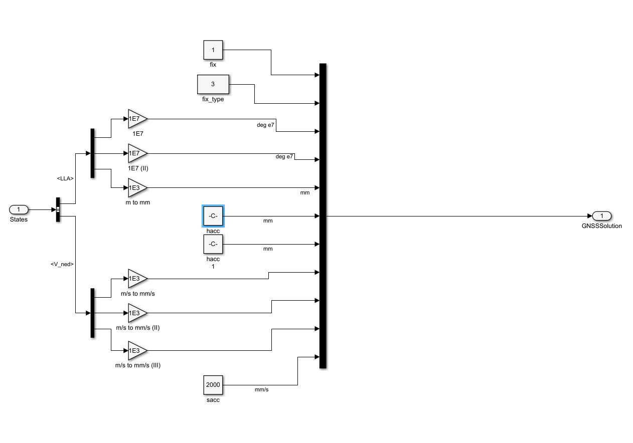
GNSS array
The angle inputs are in degrees*10^7, and the distance inputs in millimeters. The accuracy values are equivalent to the square root of the square error. These values are supposed to be computed by the GPS device and are used in the EFK for GNSS solution. However, in the configuration files user can choose between these ones or values set by user.
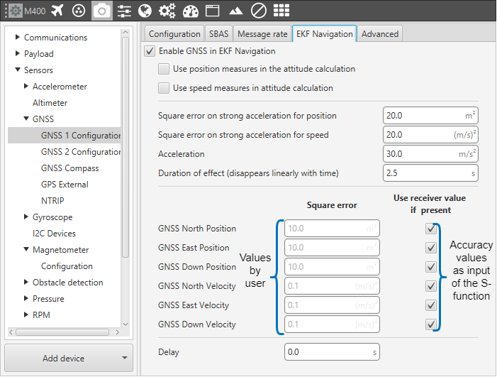
GNSS variances
RTK Example Block (Relative Position)
To enable RTK feature user has to modify the configuration (more information can be found in Veronte Autopilot Manual), and include more inputs by S-function. This input is named as Relative Position, and it requires an array of 10 elements.
Status : 0 is Data invalid and 1 is Data valid
RelPosN : North component of relative position vector (cm)
RelPosE : East component of relative position vector (cm)
relPosD : Down component of relative position vector (cm)
relPosHPN : High precision North component (mm)
relPosHPE : High precision East component (mm)
relPosHPD : High precision Down component (mm)
accN : Accuracy of relative position North component (mm)
accE : Accuracy of relative position East component (mm)
accD : Accuracy of relative position DOwn component (mm)
High precision components must be in range -99 to 99 millimeters. The full component of the relative position vector (in cm) is given by the addition of the 2 components. An example of this subgroup is shown below:
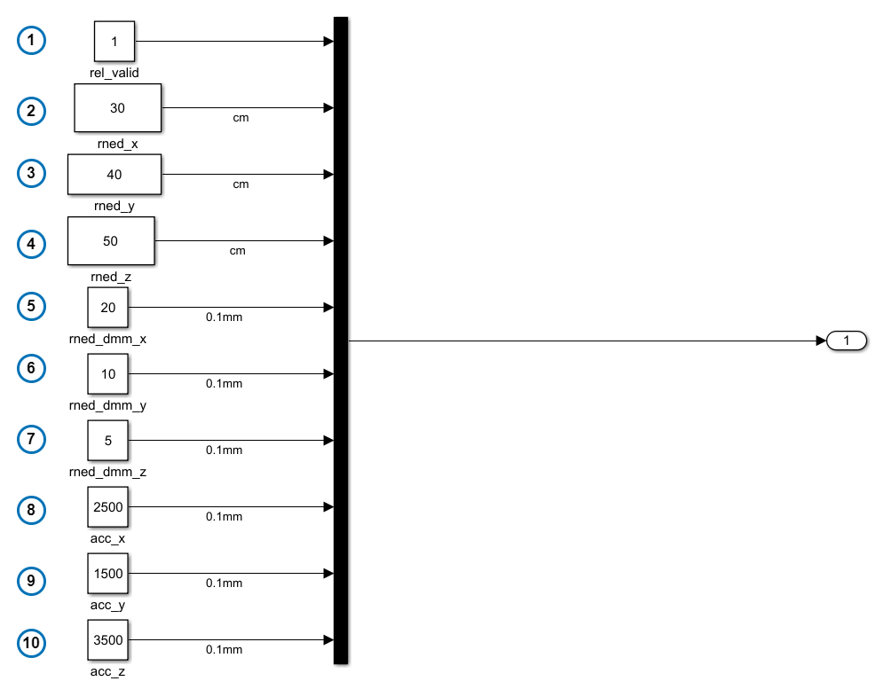
RTK inputs