Quick Start
Basic Connection Diagram
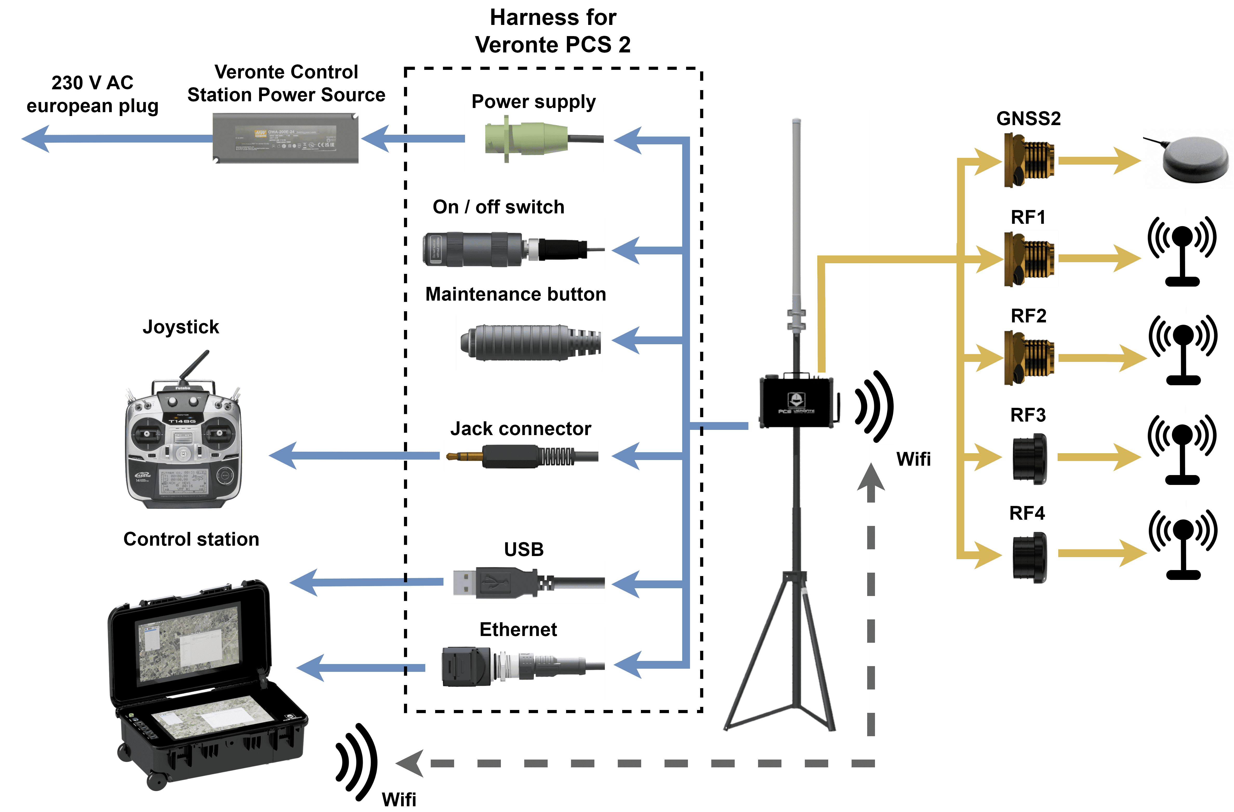
SMA Connections table |
|||||
Radio modem |
RF1 |
RF2 |
RF3 |
RF4 |
GNSS2 |
No modem |
Internal Digi radio of Autopilot 1x |
NC |
NC |
NC |
Second antenna for GNSS |
DTC |
Channel A of modem output (amplified) |
Channel B of modem output (not amplified) |
NC |
||
Silvus |
Channel A1 of modem output |
Channel A1 of modem output |
Channel A2 of modem output |
||
Microhard |
Modem output (amplified) |
NC |
NC |
||
SDL04 |
Modem output (not amplified) |
NC |
NC |
||
SDL09 or SDL24 |
Modem output (amplified if amplifier module is used) |
NC |
NC |
||
First Steps
ON/OFF
To switch on and off the PCS, it is necessary to attach the PCS Harness and connect an antenna.
By pressing the button for 2 seconds, the light will turn on and shine blue.
To turn the device off, the push button shall be pressed for 2 seconds (until the blue light turns off). The push button delay is implemented to avoid unwished disconnections.
Once the PCS is on, the connector can be detached and the system will continue working.
Warning
The connector only can be deatached in case of operating with battery and wireless. In this case the PCS will continue working, hence it will consume battery and the user has to remember to turn off the PCS after using it (plugging in the harness again).
Important
In order to not stress the battery unnecessarily, do not forget to turn off the system after using it.
Battery Charge
Veronte PCS can be connected and disconnected from the power supply during the operation without turning off the system. In case of external power supply disconnection, the smart battery managment system will switch automatically from external power supply to the internal battery.
In order to have a redundant power supply during operation and ensure the robustness of the system, it is recommended to use always the external power supply so the internal battery will be used as back-up.
PCS is provided with an internal intelligent battery charger which improves the charging process and optimizes it. In order to charge the battery, follow the next steps:
Ensure the power source is properly connected.
The Battery status shall be checked in the provided software.
Note
There is no need on turning on the system for charging the PCS. As soon as the power supply is connected, the battery starts charging.
Warning
Do NOT charge with a different power supply. It will damage the system.
Warnings
Each pin of the expansion bay connector (the connector with 16 pins) has a current limit of 4 A; except for pin 8 which has 2 A. Higher intensities may damage internal components.
Do not start a mission without a charged battery.
Make sure the distance between ground end and air end is over 5 m.
Port RS-232 has possible connections in both external harnesses (pin 19 is transmitter and pin 20 is receiver) and Expansion Bay (pin 14 is transmitter and pin 16 is receiver). CAUTION: only one of both can be used. They drive to the same input channel, but this configuration is thought to ease the connection of any device from the expansion bay if needed.
Port RS-485 is used by default by the Veronte Autopilot 1x for Ethernet connection. Please contact us before using it for other purposes.
Only one DHCP device connection can be done simultaneously. If more than one is meant to be connected, then it is needed to configure a Static IP.
Veronte PCS is IP54 protected while closed. However, it loses its water resistance meanwhile the outer cover is open.
Do not break warranty seals. Please contact us before doing it.
Do not cover the pressure purge in order to ensure the correct flow of the system
Avoid shocks during transportation or operation, some of the components could suffer damage.
Note
For safer operations, it is recomended to operate the Veronte PCS connected to an external power source, using the internal battery as back-up.
Antennas
Users must not power on a PCS without a suitable antenna or 50 \(\Omega\) load connected to the RF port.
Danger
This may damage the PCS unit.
Guarantee that no obstacles will interrupt LOS communications.
Keep the PCS in a position where the GPS antenna is facing to the open sky for better satellite view.
Operators should not stand or walk in front of any high gain antenna such as dish antennas, nor should they allow anyone else to do so.
Operators should not operate an RF transmitter or power amplifier with any of its cover removed, nor should they allow anyone else to do so.
At 2.4 GHz, operators should keep the minimum distances of the following table:
Antenna
Minimum safe distance (m) for transmitter powers
Type
Gain (dBi)
Gain Ratio
1 W
2 W
4 W
10 W
30 W
Omni
3
2
0.4
0.6
0.8
1.3
2.2
Sector
20
100
2.9
4
5.6
9
15.5
Parabolic dish
35
3162
16
22.5
32
50
87