Integration examples
Internal Radio Configuration
To configure the internal radio of the autopilot, read Digi Internal Radio - Integration examples section of 1x PDI Builder user manual.
Adjustable Antenna Mount
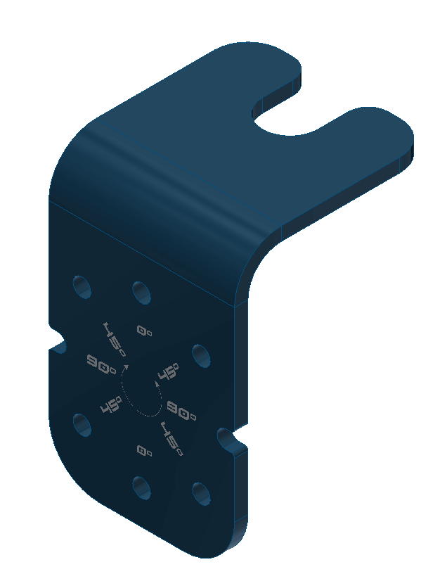
Adjustable antenna mount
The adjustable antenna mount allows to set up certain antennas at 0, 45 or 90º, depending on the polarization desired.
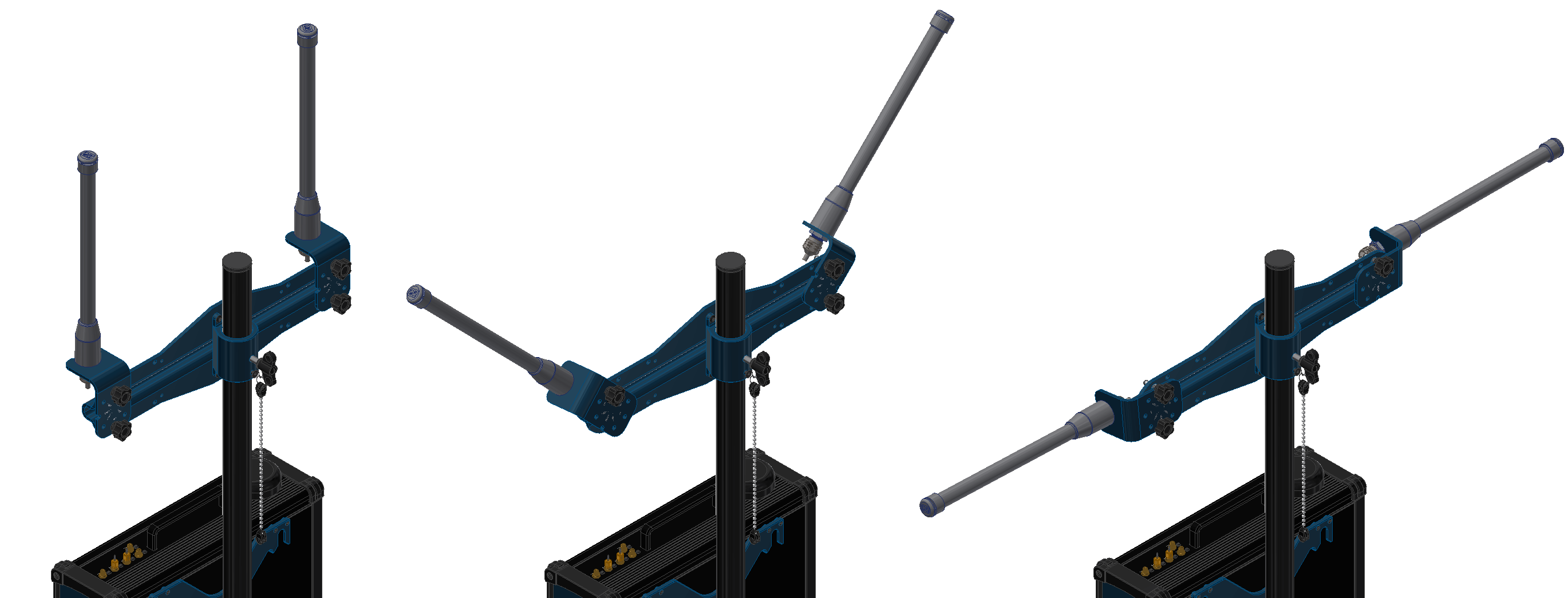
PCS antennas at 0, 45 and 90º
To attach the an antenna to the holder with the adjustable mount read the following steps:
Slide the antenna through the slot.
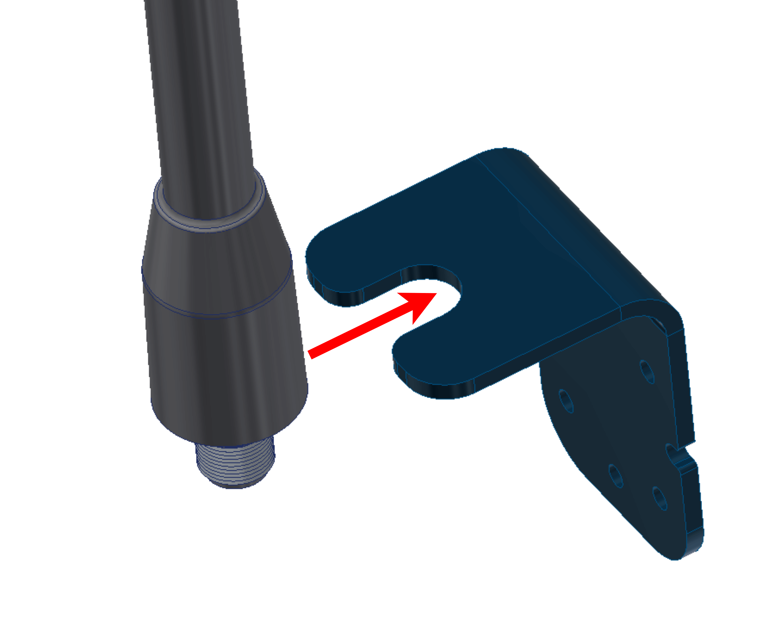
Adjustable mount - Step 1
Screw the connector and the nut to fix the antenna.
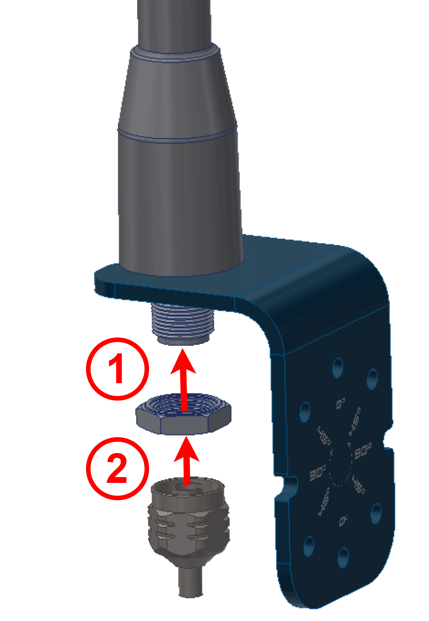
Adjustable mount - Step 2
Attach the adjustable antenna mount with both knobs. Use the holes which correspond to the desired position.
Adjustable mount - Step 3
Datalink Kit Installation and Configuration
To install a radio module in the PCS, follow the installation instructions according to the modem of the datalink kit. Click on your corresponding modem: