Electrical
Power
Veronte can use unregulated DC (6.5V to 36V). Pins used for power and ground are the same for both Ground and Air configurations.
LiPo batteries between 2S and 8S can be used without regulation needs. Remaining battery level can be controlled by the internal voltage sensor and by configuring the voltage warnings on the Pipe software.
For higher voltage installations, voltage regulators must be used. For dimensioning voltage regulators take into account that a blocked servo can activate regulator thermal protection.
Warning
Caution!! Power Veronte out of the given range can cause irreversible damage to the system. Please read carefully the manual before powering the system.
Veronte and servos can be powered by the same or different batteries. In case of having more than one battery on the system, a single point ground union is needed to ensure a good performance. The ground signal should be isolated from other noisy ground references (e.g. engines). If all grounds need to be connected, the connection should be made on the negative pole of the battery.
It is recommendable to use independent switches for autopilot and motor/actuators. During the system initialization, the PWM signal will be set to low level (0V), please make sure that actuators/motor connected support this behaviour before installing a single switch for the whole system.
Veronte I/O Signals
68 pin connector for Veronte Autopilot (frontal view)
Pin |
Signal |
Type |
Comments |
|---|---|---|---|
1 |
I/O1 |
I/O |
PWM / Digital I/O signal (0-3.3V). Protected against ESD and short circuit |
2 |
I/O2 |
I/O |
PWM / Digital I/O signal (0-3.3V). Protected against ESD and short circuit |
3 |
I/O3 |
I/O |
PWM / Digital I/O signal (0-3.3V). Protected against ESD and short circuit |
4 |
I/O4 |
I/O |
PWM / Digital I/O signal (0-3.3V). Protected against ESD and short circuit |
5 |
I/O5 |
I/O |
PWM / Digital I/O signal (0-3.3V). Protected against ESD and short circuit |
6 |
I/O6 |
I/O |
PWM / Digital I/O signal (0-3.3V). Protected against ESD and short circuit |
7 |
I/O7 |
I/O |
PWM / Digital I/O signal (0-3.3V). Protected against ESD and short circuit |
8 |
I/O8 |
I/O |
PWM / Digital I/O signal (0-3.3V). Protected against ESD and short circuit |
9 |
GND |
GROUND |
Ground signal for actuators 1-8 |
10 |
I/O9 |
I/O |
PWM / Digital I/O signal (0-3.3V). Protected against ESD and short circuit |
11 |
I/O10 |
I/O |
PWM / Digital I/O signal (0-3.3V). Protected against ESD and short circuit |
12 |
I/O11 |
I/O |
PWM / Digital I/O signal (0-3.3V). Protected against ESD and short circuit |
13 |
I/O12 |
I/O |
PWM / Digital I/O signal (0-3.3V). Protected against ESD and short circuit |
14 |
I/O13 |
I/O |
PWM / Digital I/O signal (0-3.3V). Protected against ESD and short circuit |
15 |
I/O14 |
I/O |
PWM / Digital I/O signal (0-3.3V). Protected against ESD and short circuit |
16 |
I/O15 |
I/O |
PWM / Digital I/O signal (0-3.3V). Protected against ESD and short circuit |
17 |
I/O16 |
I/O |
PWM / Digital I/O signal (0-3.3V). Protected against ESD and short circuit |
18 |
GND |
GROUND |
Ground signal for actuators 9-16 |
19 |
RS 232 TX |
Output |
RS 232 Output (-13.2V to 13.2V Max, -5.4V to 5.4V Typical). Protected against ESD and short circuit |
20 |
RS 232 RX |
Input |
RS 232 Input (-25V to 25V Max, -0.6V Low and 2.4V High Threshold). Protected against ESD and short circuit |
21 |
GND |
GROUND |
Ground signal for buses |
22 |
Analog 4 |
Input Analog |
Input 0-3V. Protected against ESD and short circuit |
23 |
Analog 5 |
Input Analog |
Input 0-3V. Protected against ESD and short circuit |
24 |
GND |
GROUND |
Ground signal for buses |
25 |
CanA P |
I/O |
CANbus interface, up to 1Mbps (2.3V Typical, 1.2V-2.3V Differential). Protected against ESD |
26 |
CanA N |
I/O |
Twisted pair with a 120Ω Zo recommended (2.3V Typical, 1.2V-2.3V Differential). Protected against ESD |
27 |
GND |
GROUND |
Ground signal for buses |
28 |
CANB_P |
I/O |
CANbus interface. It supports data rates up to 1 Mbps. Protected against ESD |
29 |
CANB_N |
I/O |
Twisted pair with a 120 Ω Zo recommended. Protected against ESD |
30 |
GND |
GROUND |
Ground signal for buses |
31 |
I2C_CLK |
Output |
Clk line for I2C bus (0.3V to 3.3V). Protected against ESD and short circuit |
32 |
I2C_DATA |
I/O |
Data line for I2C bus (0.3V to 3.3V). Protected against ESD and short circuit |
33 |
GND |
GROUND |
Ground for 3.3V power supply |
34 |
3.3V |
POWER |
3.3V - 100mA power supply. Protected against ESD short circuit with 100mA resettable fuse |
35 |
GND |
GROUND |
Ground for 5V power supply |
36 |
5V |
POWER |
5V – 100mA power supply. Protected against ESD short circuit with 100mA resettable fuse |
37 |
GND |
GROUND |
Ground for analog signals |
38 |
ANALOG_1 |
Input |
Analog input 0-3V. Protected against ESD and short circuit |
39 |
ANALOG_2 |
Input |
Analog input 0-3V. Protected against ESD and short circuit |
40 |
ANALOG_3 |
Input |
Analog input 0-3V. Protected against ESD and short circuit |
41 |
GND |
GROUND |
Ground for FTS signals |
42 |
FTS1_OUT |
Output |
Deadman signal from comicro. Protected against ESD and short circuit |
43 |
FTS2_OUT |
Output |
!SystemOK Bit. Protected against ESD and short circuit |
44 |
GND |
GROUND |
Ground signal for safety buses |
45 |
V_ARB_TX |
Output |
Veronte comicro UART output to activate safety mechanism. Protected against ESD and short circuit |
46 |
V_ARB_RX |
Input |
Veronte comicro UART output to activate safety mechanism. Protected against ESD and short circuit |
47 |
GND |
GROUND |
Ground signal comicro power supply |
48 |
V_ARB_VCC |
POWER |
Veronte comicro power (6.5V to 36V). Protected against ESD and reverse polarity |
49 |
FTS3_OUT_MPU |
Output |
MPU alive voting signal, to use with 4xVeronte. It is a Square Wave at [100,125] Hz. Protected against ESD and short circuit |
50 |
OUT_RS485_P |
Output |
Non-inverted output from RS485 bus (-7V to 12V Max, -2.3V to 2.3V Typical). Protected against ESD and short circuit |
51 |
OUT_RS485_N |
Output |
Inverted output from RS485 bus (-7V to 12V Max, -2.3V to 2.3V Typical). Protected against ESD and short circuit |
52 |
IN_RS845_N |
Input |
Inverted input from RS485 bus (-7V to 12V Max, -2.3V to 2.3V Typical). Protected against ESD and short circuit |
53 |
IN_RS845_P |
Input |
Non-inverted output from RS485 bus (-7V to 12V Max, -2.3V to 2.3V Typical). Protected against ESD and short circuit |
54 |
RS-485_GND |
GND |
Ground for RS-485 bus |
55 |
EQEP_A |
I/O |
DIGITAL output / DIGITAL input / Encoder quadrature input A (0-3.3V). Protected against ESD and short circuit |
56 |
EQEP_B |
I/O |
DIGITAL output / DIGITAL input / Encoder quadrature input B (0-3.3V). Protected against ESD and short circuit WARNING!: Only use it as digital I/O with Veronte units of Hardware version 4.5 or lower |
57 |
EQEP_S |
I/O |
DIGITAL output / DIGITAL input / Encoder strobe input (0-3.3V). Protected against ESD and short circuit |
58 |
EQEP_I |
I/O |
DIGITAL output / DIGITAL input / Encoder index input A (0-3.3V). Protected against ESD and short circuit |
59 |
GND |
GROUND |
Ground for encoders |
60 |
V_USB_DP |
I/O |
Veronte USB data line. Protected against ESD |
61 |
V_USB_DN |
I/O |
Veronte USB data line. Protected against ESD |
62 |
V_USB_ID |
I/O |
Veronte USB ID line. Protected against ESD and short circuit |
63 |
FTS_OUT_MPU |
Output |
Abort mission voting signal from MPU, to use with 4xVeronte. Bit Low (0V) if mission OK. High (3.3V) if mission wants to be terminated. Protected against ESD and short circuit |
64 |
FTS2_OUT_MPU |
Output |
Abort mission voting signal 2 from MPU, to use with 4xVeronte. Bit Low (0V) if mission OK. High (3.3V) if mission wants to be terminated. Protected against ESD and short circuit |
65 |
GND |
GROUND |
Veronte ground input |
66 |
ND |
GROUND |
Veronte ground input |
67 |
VCC |
POWER |
Veronte power supply (6.5V to 36V). Protected against ESD and reverse polarity |
68 |
VCC |
POWER |
Veronte power supply (6.5V to 36V). Protected against ESD and reverse polarity |
Warning
Remember!! All Veronte’s GND pins are common.
Flight Termination System (FTS)
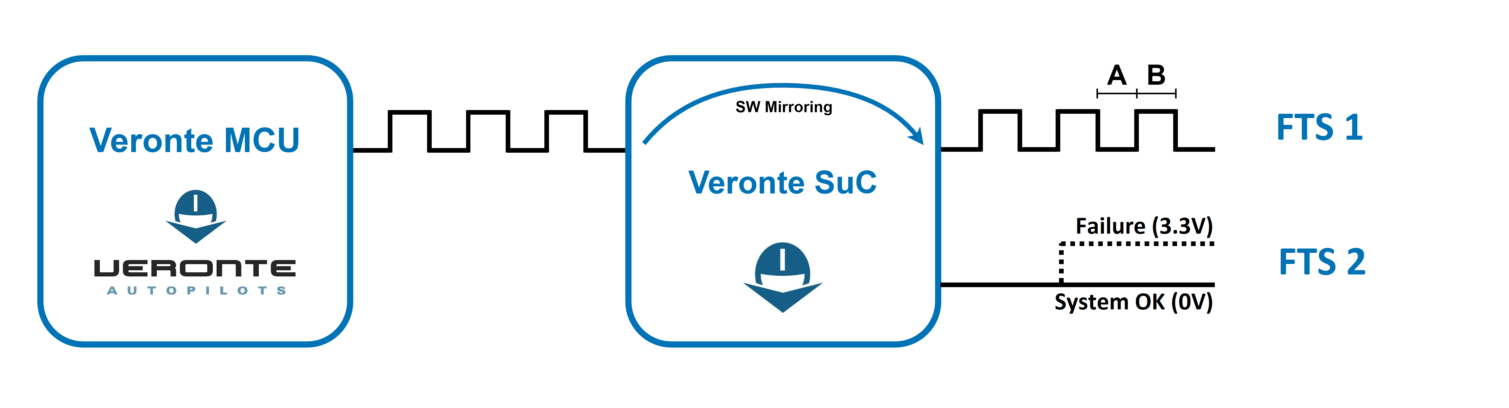
Flight Termination System
Veronte integrates two different FTS pins (42 and 43):
FTS1 - Deadman (Pin 42): On this pin, Veronte outputs a square wave with A = ~5ms and B = ~5ms (3.3V). Its frequency can be higher right after the rebooting (around 300-400Hz), but A and B must be always < 8ms.
FTS2 - !SystemOK (Pin 43): Its output is 0V when the system is working as expected and 3.3V when some error is detected. In detail, pin 43 goes high if A > 8ms or B > 8ms in the deadman signal sent by the Main Processor Unit (MPU).
Joystick
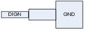
To use the joystick in the system, connect the PPMout of the trainer port to a digital input of Veronte and configure that digital input as the radio input in Pipe.
If the PPM level is 3.3V, pins 1-8, 10-17 and 55-58 pins can be used.
Veronte is compatible with standard Pulse Positon Modulation (PPM) signals, Futaba radios between 8 and 12 channels are recommended.
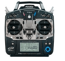
Futaba T10 Joystick
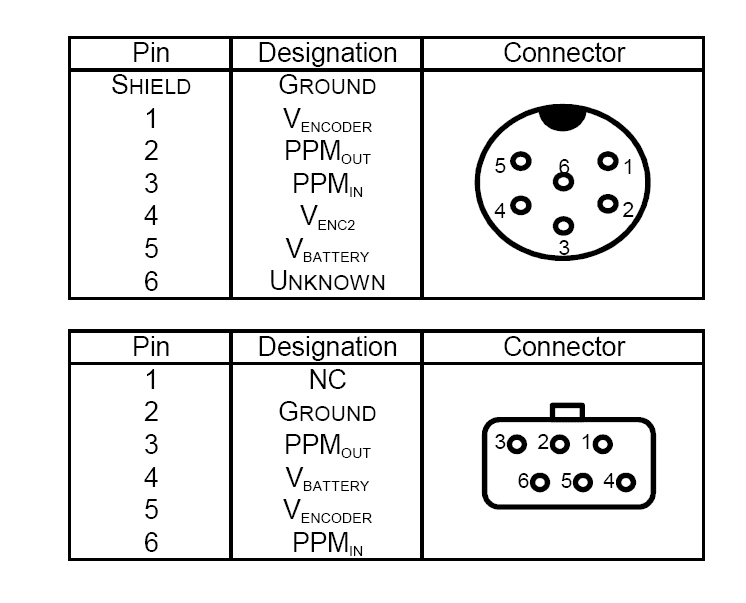
Futaba T10 pinout
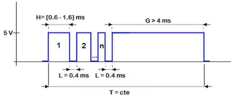
PPM signal
As default, channel 8 is reserved for manual / auto switch. High level is used for automatic flight and low level for manual control. This channel can be configured on Veronte Pipe.
Warning
Caution!! PPM signal must be into the Veronte voltage ranges. Some joysticks may need an adaptation board, please ask our team to check compatibility.
Veronte connector for CS is provided with 3.5mm stereo plug connector as follows:
PPM pinout
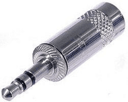
PPM connector