Servo Configuration
The M400 configuration process can be performed by using a VerontePipe software version connected with the hardware system and the Autopilot as explained in the section Hardware Installation of the manual.
Servos Output
The first step of the process is the servos configuration.
In this case, the controls of the airplane are the four electric motors. Motors can be controlled by changing their thrust, so each one of them corresponds to a pin of the connector and they must be positioned in the same order in an S vector who represents the Actuator Output. It is possible to connect any pin to any command but the easiest way to perform it and avoid confusion is by following the pins number.
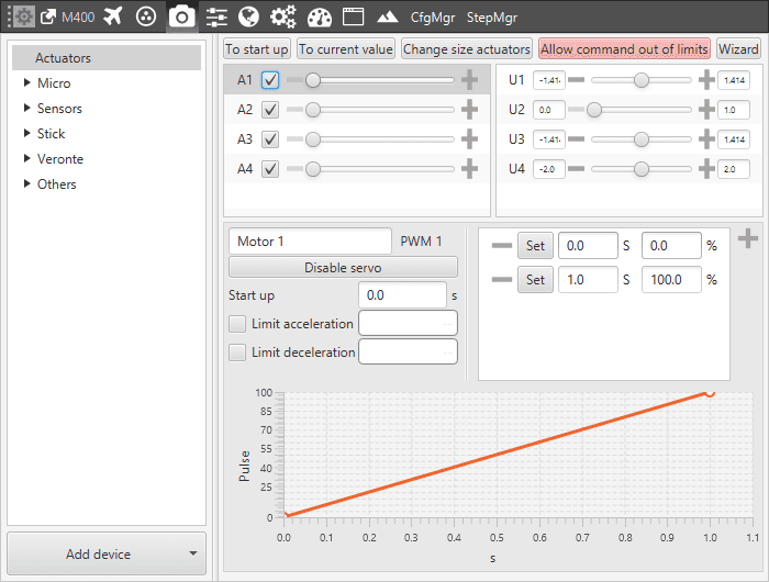
Output-pin connections
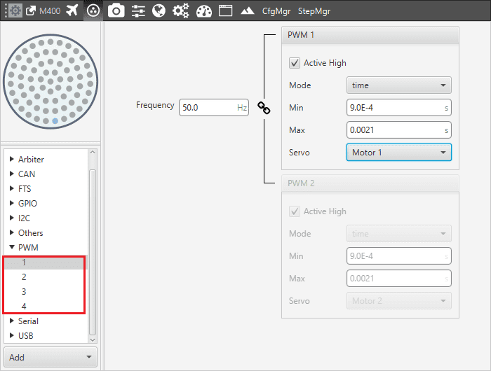
In this case, it is possible to use 4 pins:
Output 1 – Actuator Output s1 (Motor 1)
Output 2 – Actuator Output s2 (Motor 2)
Output 3 – Actuator Output s3 (Motor 3)
Output 4 – Actuator Output s4 (Motor 4)
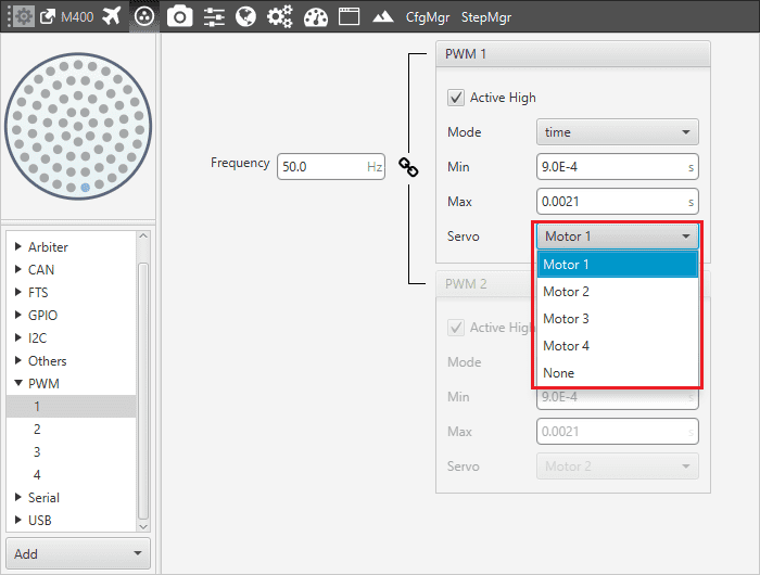
Output 1 – pin 1 configuration
SU Matrix
At this point, the S vector is defined and the SU matrix can be edited. By clicking on Edit it is possible to configure the relation between the controller outputs (U vector) and the servo movements (S vector).
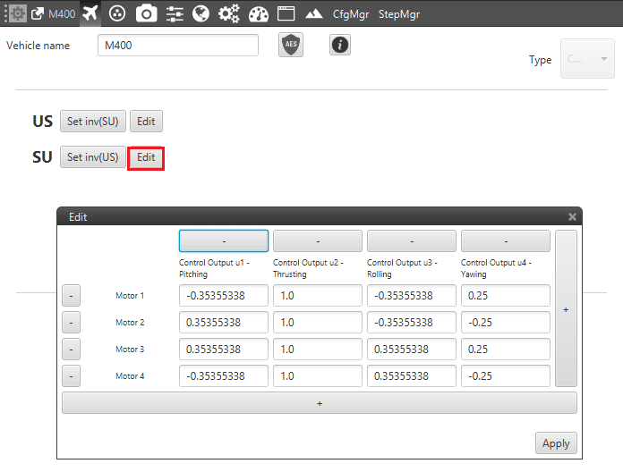
Output 1 – SU matrix edit
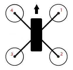
SU matrix and motors numbers
The M400 is configured as follow:
Pitch Angle Control: Control Output 1 is configured to perform a positive pitch angle change when motors 1-4 decrease their RPMs and motors 2-3 increase RPM value.
Thrust Control: the Control Output 2 is the one that allows a thrusting change (0-1).
Roll Angle Control: Control Output 3 is configured to perform a positive roll angle change when motors 1-2 decrease their RPMs and motors 3-4 increase RPM value.
Yaw Angle Control: Control Output 4 is configured to perform a positive yaw angle change when motors 2-4 decrease their RPMs and motors 1-3 increase RPM value, in this case with different proportions.
Warning
This panel shows the reference system of the aircraft too. It must be positioned in the same way of the Autopilot’s one. If it results different, it can be edited by clicking on the corresponding axis in order to reverse its direction.
System Trim
As a final step, the system has to be trimmed. In this case, each motor will have a minimum and maximum value as shown in the picture.
M400 trim
Minimum: 0.
Maximum: 1.