Integration examples
Arbitration configuration
The following arbitration configuration has been done in conjunction with the integration example detailed in the Autopilots 1x configuration - Integration examples section of the 1x PDI Builder user manual. Also, this is the recommended configuration and a good starting point.
The following schema broadly summarizes the configuration that will be explained:

Arbitration configuration diagram
Important
All the Ids represented in the schema are the default ones and those that will be used throughout this example, but users can change them as they wish.
Nonetheless, the Ids designated for arbitration in this configuration must match those entered in the Autopilots 1x configuration of the 1x PDI Builder software.
AP 1 arbitration Id |
AP 2 arbitration Id |
AP 3 arbitration Id |
Status message Id |
|---|---|---|---|
8 |
9 |
10 |
255 |
Users should follow the steps below:
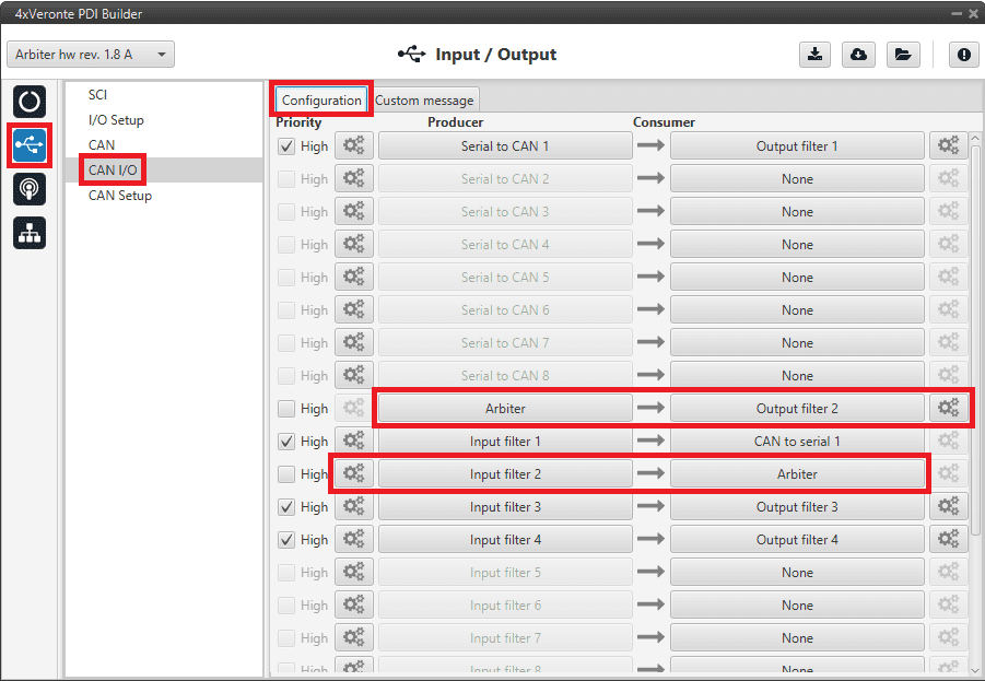
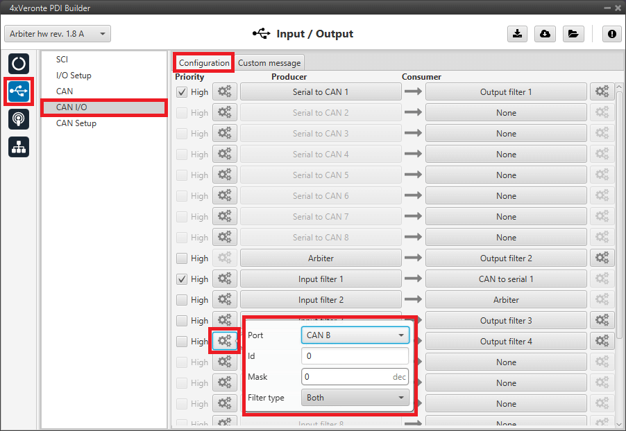
Go to Input/Output menu \(\rightarrow\) CAN I/O panel \(\rightarrow\) Configuration tab.
For sending the status and score messages to the Autopilots 1x, connect the Arbiter producer to an Output filter consumer, in this case Output filter 2 has been selected.
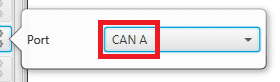
This Output filter must be set to CAN A port, as this is the CAN Bus employed by the arbiter to communicate with Autopilots 1x. For more information on the CAN architecture of an Autopilot 4x, see the General description - Technical section of the 4x Hardware Manual.

For receiving the ready and arbitration variables messages from the Autopilots 1x, connect an Input filter producer to the Arbiter consumer, in this case Input filter 2 has been selected.
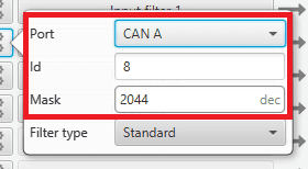
To read these message correctly, it is necessary to configure this Input filter to CAN A port, with Id 8 and mask 2044 (decimal format), this will read messages with Ids from 8 to 10.
Note
The following table shows the Ids and mask in binary and decimal format used in this example.
Decimal format
Binary format
AP 1 arbitration Id
8
000 0000 1000
AP 2 arbitration Id
9
000 0000 1001
AP 3 arbitration Id
10
000 0000 1010
Mask
2044
111 1111 1100
Arbitration configuration - CAN I/O configuration
Arbitration configuration - Output filter configuration
Arbitration configuration - Input filter configuration
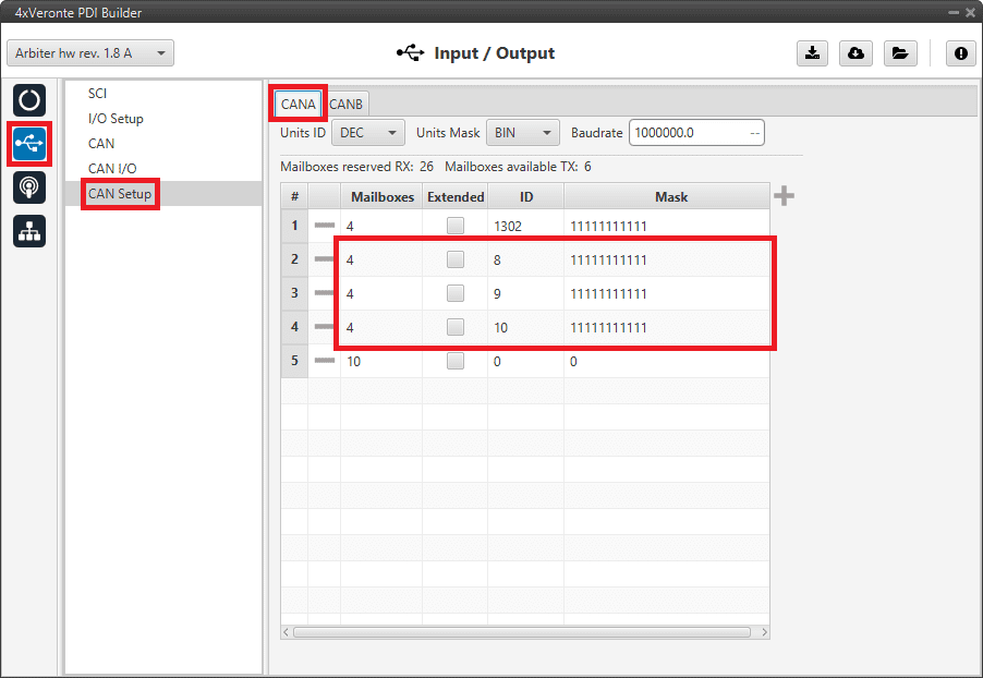
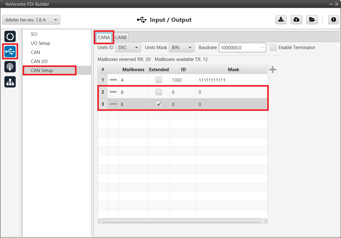
Go to Input/Output menu \(\rightarrow\) CAN Setup panel \(\rightarrow\) CAN A tab.
Configure at least 4 mailboxes in CAN A for each arbitration Id:
Arbitration configuration - CAN Setup configuration
Go to Arbitration menu \(\rightarrow\) Config panel.
Here users have to configure the necessary parameters for the arbitration algorithm. For more information on this algorithm, see Arbitration section of the present manual.
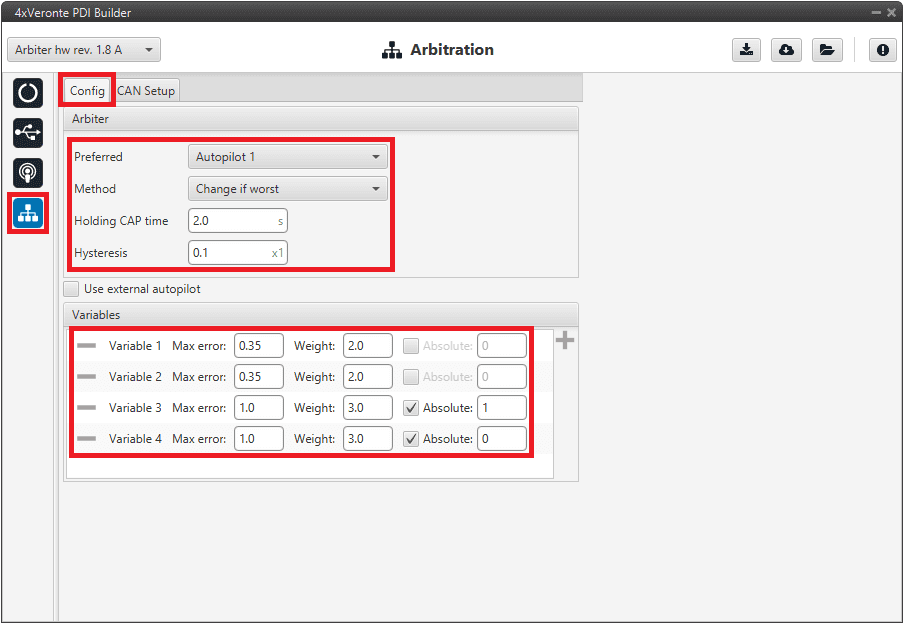
Arbitration configuration - Config (Arbitration) configuration
Arbiter: These are the recommended values for each parameter:
Preferred: Autopilot 1
Method: Change if worst
Holding CAP time: 2.0 s
Hysteresis: 0.1
Variables: Add as many variables as have been configured in the 1x PDI Builder software as arbitration variables.
The variables chosen in this example, as well as their configuration parameters, are presented below:
Variable
Max error
Weight
Absolute
Roll
0.35
2.0
-
Pitch
0.35
2.0
-
Position not fixed
1.0
3.0
Enabled | 1
Custom Arbitration Variable
1.0
3.0
Enabled | 0
Note
Remember that the number for each variable is assigned with the CAN I/O configuration in the arbiter consumer. With this consumer, arbitration variables are selected with their corresponding numbers.
Go to Arbitration menu \(\rightarrow\) CAN Setup panel.
Finally, users must enable the sending of status and scores messages from the arbiter and configure the CAN Ids described above.
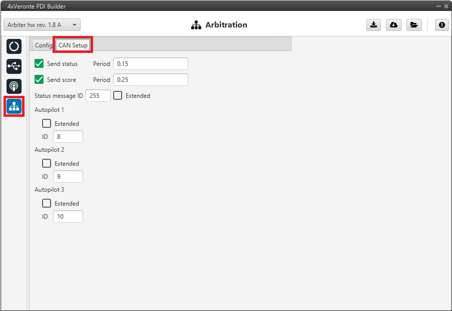
Arbitration configuration - CAN Setup (Arbitration) configuration
Send status: Enabled
Period: 0.15
Send score: Enabled
Period: 0.25
Status message ID: 255
Autopilot 1: ID 8
Autopilot 2: ID 9
Autopilot 3: ID 10
CAN tunnel
A CAN tunnel is the continuous transmission of messages between both CAN ports. Veronte Autopilot 4x can use any arbiter as a CAN tunnel, or both at the same time. The following diagram shows the physical connections of CAN buses inside the Autopilot 4x.
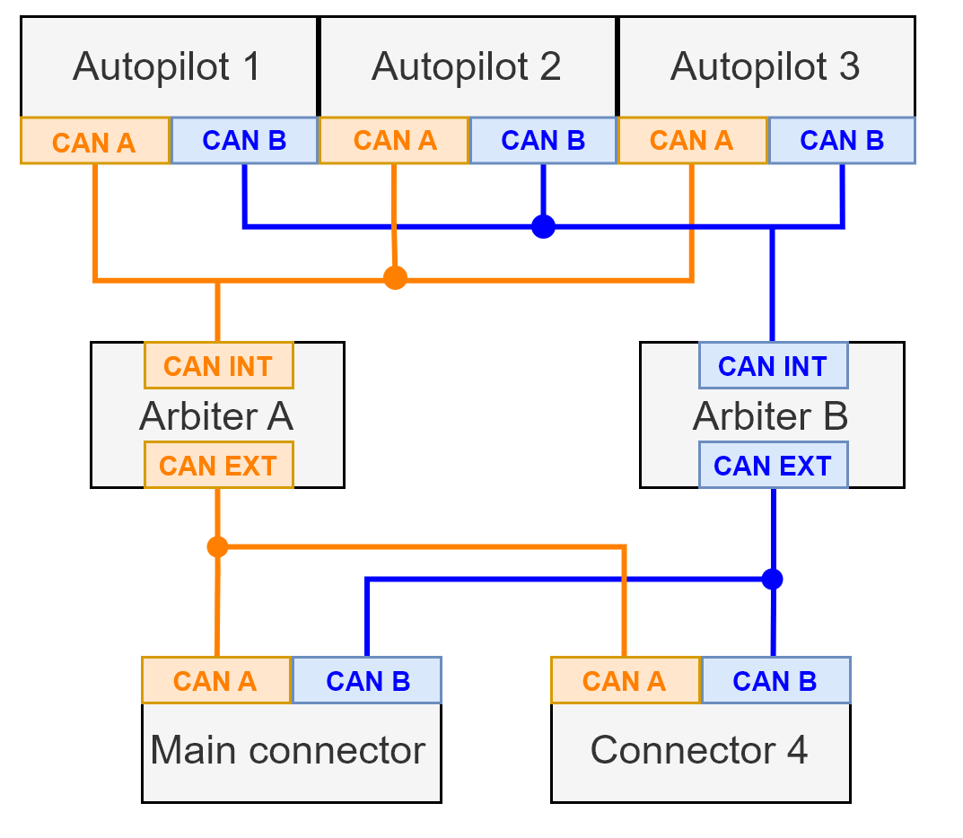
Internal CAN connections diagram
Note
The following explanation is an example of how to configure arbiter A as a CAN tunnel. To configure arbiter B, the procedure is the same, but changing the arbiter selected.
In this example, a transparent tunnel will be created. So, any messages received on Interface INT (named as CAN A in 4x PDI Builder) will be sent to Interface EXT (named as CAN B) and vice versa.
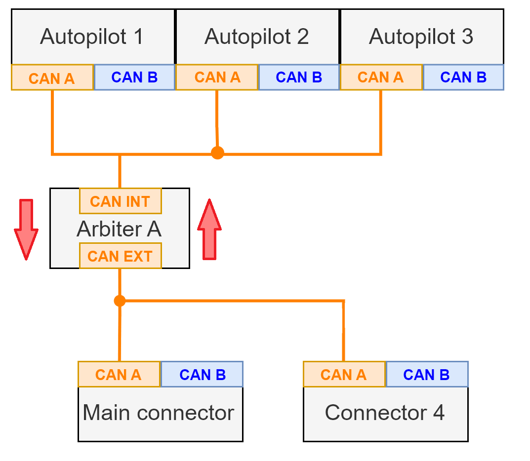
CAN tunnel - Arbiter A diagram
Optionally, the mailboxes can be equally distributed to support both: standard and extended CAN IDs.
Create a new mailbox entry for Interface INT.
Go to Input/Output menu \(\rightarrow\) CAN Setup panel \(\rightarrow\) CAN A tab.
Assign half of the mailboxes to it and set a Mask of 0.
CAN tunnel - CAN Setup configuration: CAN A
Create a new mailbox entry for Interface EXT. Repeat the same configuration as explained in step 1, but this time for CAN B.
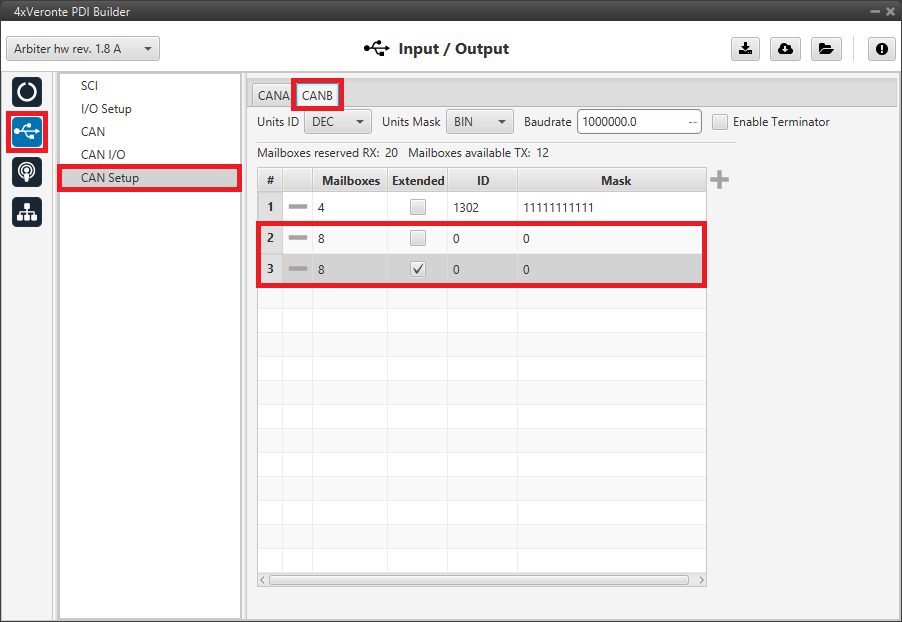
CAN tunnel - CAN Setup configuration: CAN B
Go to Input/Output menu \(\rightarrow\) CAN I/O panel \(\rightarrow\) Configuration tab.
Configure an Input filter on CAN A, with CAN id 0, a Mask of 0 and Both as frame format type. In this case, Input filter 3 has been chosen.
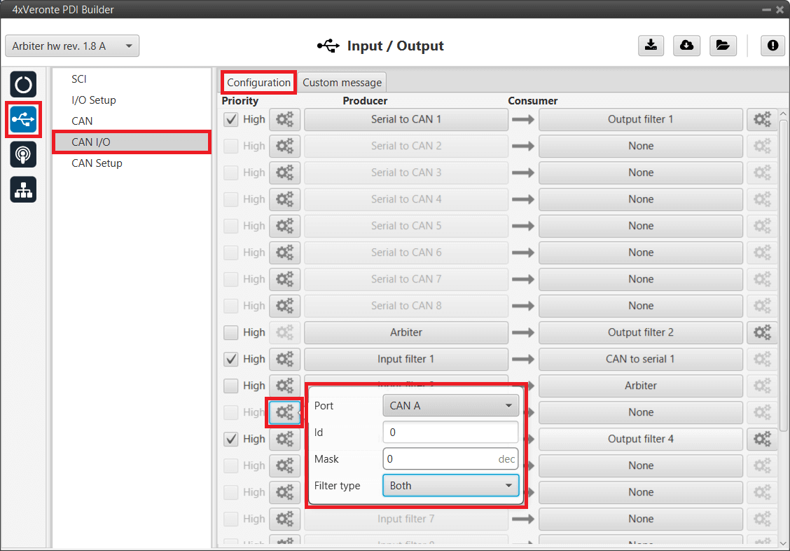
CAN tunnel - Input filter configuration for CAN A
Bind an Output filter to the Input filter previously configured and, configure the Output filter to CAN B. In this case, Output filter 3 has been chosen.
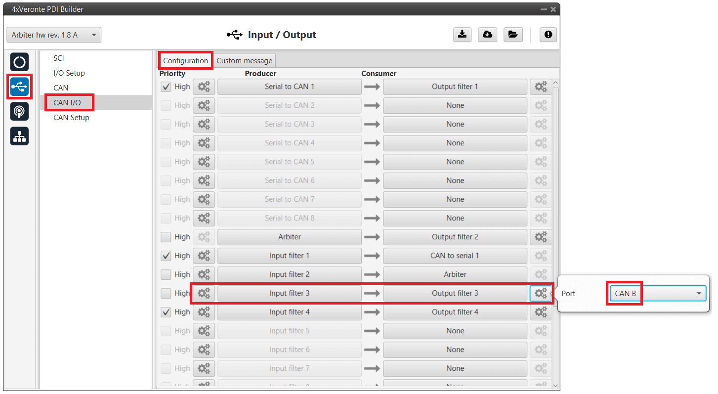
CAN tunnel - Output filter configuration for CAN B
Configure another Input filter on CAN B, with CAN id 0, a Mask of 0 and Both as frame format type. In this case, Input filter 4 has been chosen.
CAN tunnel - Input filter configuration for CAN B
Bind an Output filter to the Input filter previously configured and, configure the Output filter to CAN A. In this case, Output filter 4 has been chosen.
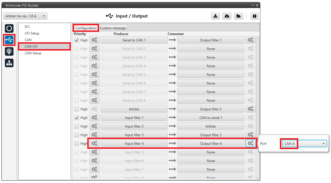
CAN tunnel - Output filter configuration for CAN A
GPIO command
The following are the steps to send a GPIO command from the Veronte Autopilot 1x, receive it at Arbiter and process it, so that Arbiter carries out the command. GPIO Command is very similar to PWM command with a few exceptions.
Warning
For the reception of CAN messages, Mailboxes need to be configured accordingly.
1x PDI Builder side
Go to Input/Output menu \(\rightarrow\) CAN Setup panel \(\rightarrow\) Configuration tab.
Connect a CAN GPIO remote producer to an Output filter consumer:
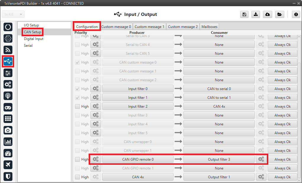
1x PDI Builder - CAN Setup configuration
CAN GPIO remote must be configured. For more information on its configuration, see CAN Setup - Input/Output section of the 1x PDI Builder user manual.
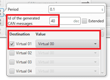
1x PDI Builder - CAN GPIO remote configuration
Go to Automations menu.
Create a new automation to activate the GPIO using an Output action:
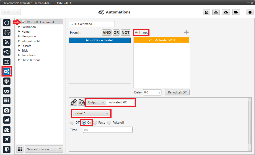
1x PDI Builder - Automation configuration
4x PDI Builder side
Go to Input/Output menu \(\rightarrow\) CAN Setup panel.
Create the mailbox to receive the message configured in the 1x PDI Builder (ID 40):
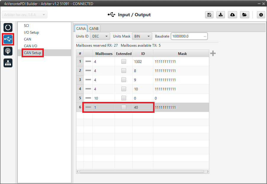
4x PDI Builder - CAN Setup configuration
Go to Input/Output menu \(\rightarrow\) CAN I/O panel \(\rightarrow\) Configuration tab.
Finally, connect an Input filter producer with the right CAN ID to a CAN GPIO consumer.
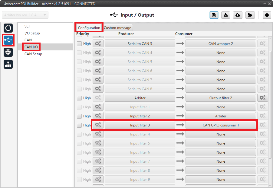
4x PDI Builder - CAN I/O configuration
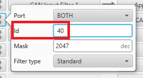
4x PDI Builder - Input filter configuration